
Subscribe to Our Youtube Channel
Related Manuals for IntesisBox IBOX-BAC-MBRTU-100


Summary of Contents for IntesisBox IBOX-BAC-MBRTU-100
- Page 1 ® IntesisBox BACnet/IP Server Modbus RTU Master User's manual Issue Date: 17/12/2012 r14 eng...
- Page 2 ® User’s Manual r14 eng IntesisBox BACnet/IP Server - Modbus RTU Master © Intesis Software S.L. All Rights Reserved. Information in this document is subject to change without notice. The software described in this document is furnished under a license agreement or nondisclosure agreement. The software may be used only in accordance with the terms of those agreements.
- Page 3 Gateway for the integration of Modbus RTU slave devices into BACnet/IP control systems. Models available for this gateway, with their following Order codes: IBOX-BAC-MBRTU-100 Tiny model supporting connection to up to 254 Modbus slave devices and 110 internal datapoints. IBOX-BAC-MBRTU-A Basic model supporting connection to up to 254 Modbus slave devices and 500 internal datapoints.
-
Page 4: Table Of Contents
Power device ....................11 Connect to Modbus ..................12 Connect to BACnet ..................12 Connect to PC (LinkBoxBacnet) ..............12 LinkBoxBacnet. Configuration & monitoring of IntesisBox BACnet series ....14 Project configuration ..................14 5.1.1 Connection configuration ................ 14 5.1.2 Signals configuration ................ -
Page 5: Description
BACnet/IP devices to perform subscription (COV) requests, and also read and write its internal points. From the Modbus system point of view, IntesisBox simulates a Modbus master device, the readings of the Modbus slave device(s) is performed by IntesisBox by automatic continuous polling. -
Page 6: Functionality
1.2 Functionality The integration operation is as follow: From the Modbus system point of view, after the start up process, IntesisBox reads continuously the points configured to be read in the Modbus slave devices, and updates in its memory all the values received from the Modbus system. -
Page 7: Capacity Of Intesisbox
Maximum number of Modbus slave devices allowed by IntesisBox. Slave devices There are different models of IntesisBox BACnet/IP Server - Modbus RTU Master, with different capacity every one of them. Tiny model supporting connection to up to 110 internal data points. -
Page 8: Interfaces
IntesisBox. The types of networks supported by IntesisBox are: RS485 2-wire (up to 254 slave devices are allowed by IntesisBox, thus up to 254 slave devices in the same RS485 network can be integrated with just one IntesisBox, installing additional line repeaters where necessary). - Page 9 Communication parameters of IntesisBox's Modbus interface (baud rate, data bits, stop bits, parity) are fully configurable to adapt to any slave device. Of course IntesisBox and all the slave devices connected to the Modbus network must use the same communication parameters.
-
Page 10: Quick Setup
3. Quick Setup 1. Install LinkBoxBacnet. Details in section 5 2. Install IntesisBox in the desired installation site (DIN rail mounting inside a metallic industrial cabinet connected to ground is recommended). 3. Power up and connect the communication cables. Details in section 4. -
Page 11: Connection
Figure 4.1 Device connection diagram Ensure proper space for all connectors when mounted. The items supplied by Intesis Software for this integration are: IntesisBox BACnet/IP Server - Modbus RTU Master hardware Console cable. Standard DB9F-DB9M cable 1.8 meter long. ... -
Page 12: Connect To Modbus
LinkBoxBacnet Manual (section 5). 4.3 Connect to BACnet Connect the communication cable coming from the network hub or switch to the ETH port (Figure 4.1) of IntesisBox. The cable to be used depends on where the IntesisBox is being connected: ... - Page 13 IntesisBox BACnet/IP Server - Modbus RTU Master Ethernet: Using the ETH port (Figure 4.1) of IntesisBox. How to check connectivity is explained in section 4.3. Serial cable: To connect the device to the PC the serial cable supplied should be plugged to the PC console port (Figure 4.1).
-
Page 14: Linkboxbacnet. Configuration & Monitoring Of Intesisbox Bacnet Series
(if the Software is already installed) or it can be downloaded from the link that can be found in the installation sheet supplied with the IntesisBox. In this section only the specific project configuration for IntesisBox BACnet/IP Server - Modbus RTU Master is going to be explained. - Page 15 Gateway: Enter the Default Gateway address (router address) in case the gateway (IntesisBox) is in a different sub network than other BACnet devices (supplied by the network administrator). Leave blank if there is no need of router address. ...
- Page 16 Version: Select the gateway model used: tiny,basic or extended. You can check the gateway model in the identification given by the device when it connects to LinkBoxBacnet, it appears in the IntesisBox Communication Console window once connected to the gateway IntesisBox_Bacnet_Modbus-100…...
-
Page 17: Signals Configuration
Slave #: Enter the slave number configured in the Modbus device. 5.1.2 Signals configuration Select the Signals tab (Figure 5.5) to configure the signals list (the IntesisBox internal points). More information about the meaning of the columns can be found in the tables below. - Page 18 (from top to bottom) in the devices list Modbus Code Description Modbus function code to be used by IntesisBox to read, to write or to read/write the point in the slave device. Values 0- Communication Error...
- Page 19 Consult documentation of Modbus device(s) to integrate for information about Modbus data format of the points desired to integrate. Address Description It's the Modbus register address to use by IntesisBox to read/write the point into the Modbusdevice. Edit mode Text edit or AutoEnumeration 19 / 27 ©...
- Page 20 1 in Frac column. Then the value decoded by IntesisBox from the slave will be divided by 10, and the value will be multiplied by 10 before writing to the slave, thus will be the real value in the device (including integer and fractional part).
- Page 21 ® User’s Manual r14 eng IntesisBox BACnet/IP Server - Modbus RTU Master Description BACnet object type for the signal. Values AI = Analog Input. AO = Analog Output. AV = Analog Value. DI = Digital Input.
-
Page 22: How To Configure Read/Write Points
Modbus function codes must be used for read and for write actions (consult the slave documentation for details of what function codes must be used for read and for write). Use the following criteria for configuration of this kind of points in IntesisBox: 22 / 27 ©... - Page 23 Modbus Code and select a BACnet Type Output or Value for the point (i.e. AO, AV, BO, BV, MO, MV). With this, IntesisBox will use function code 03 for read the point in every polling cycle, and whenever a new value for the point is received from BACnet, the new value will be written in the Modbus slave device using function code 06.
-
Page 24: Saving The Configuration
® User’s Manual r14 eng IntesisBox BACnet/IP Server - Modbus RTU Master 5.1.4 Saving the configuration When the configuration of the project is finished follow the next steps: 1. Click the button Save. Once accepted the pop-up message, that will save the project in the folder on hard disk (more information in LinkBoxBacnet Manual). - Page 25 BACnet/IP Server - Modbus RTU Master 5. Once in the configuration window again, click on exit. The configuration is ready to be sent to the IntesisBox (check LinkBoxBacnet Manual) The configuration cannot be received from the gateway to LinkBoxBacnet, it can only be sent.
-
Page 26: Mechanical & Electrical Characteristics
® User’s Manual r14 eng IntesisBox BACnet/IP Server - Modbus RTU Master 6. Mechanical & electrical characteristics Plastic, type PC (UL 94 V-0). Enclosure Dimensions: 107mm x 105mm x 58mm. Colour Light Grey. RAL 7035. 9 to 30Vdc +/-10%, Max.: 125mA. -
Page 27: Dimensions
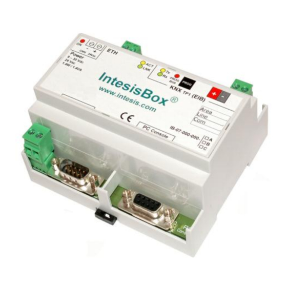
® User’s Manual r14 eng IntesisBox BACnet/IP Server - Modbus RTU Master 7. Dimensions Power Ethernet port Modbus RTU ports Console 58 mm port 107 mm 105 mm Free space recommended to install the device into a cabinet (wall or DIN rail mounting),...
Need help?
Do you have a question about the IBOX-BAC-MBRTU-100 and is the answer not in the manual?
Questions and answers