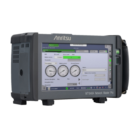
Anritsu MT1040A Operation Manual
Transport modules
Hide thumbs
Also See for MT1040A:
- Quick reference manual (11 pages) ,
- Manual (36 pages) ,
- Configuration manual (36 pages)
Table of Contents
Advertisement
Quick Links
MT1040A
MT1040A
Transport Modules
Transport Modules
Operation Manual
Operation Manual
Eighth Edition
Eighth Edition
For safety and warning information, please read this
For safety and warning information, please read this
manual
manual before attempting to use the equipment.
before attempting to use the equipment.
Keep this manual with the equipment.
Keep this manual with the equipment.
ANRITSU CORPORATION
ANRITSU CORPORATION
Document No. M-W4038AE-8.0
Advertisement
Table of Contents

Related Manuals for Anritsu MT1040A


Summary of Contents for Anritsu MT1040A
- Page 1 MT1040A MT1040A Transport Modules Transport Modules Operation Manual Operation Manual Eighth Edition Eighth Edition For safety and warning information, please read this For safety and warning information, please read this manual manual before attempting to use the equipment. before attempting to use the equipment.
- Page 2 Operation Manual 21 July 2020 (First Edition) 26 August 2021 (Eighth Edition) Copyright © 2020-2021, ANRITSU CORPORATION. All rights reserved. No part of this manual may be reproduced without the prior written permission of the publisher. The operational instructions of this manual may be changed without prior notice.
- Page 3 About This Manual About This Manual This operation manual describes both the basic operation of the MT1040A Network Master Pro as well as the operations available via interface options and predefined applications/tests. MT1040A Transport Modules Operation Manual (this manual) MT1040A Transport Modules Operation Manual (this manual)
-
Page 4: Table Of Contents
Table of Contents Table of Contents Table of Contents Table of Contents 0 0 Table of Contents Table of Contents 1 1 Introduction Introduction 1.1 Mainframe Mainframe 1.2 Modules Modules 1.2.1 100G Multirate Module 1.2.2 400G (QSFP-DD) Multirate Module 1.2.3 400G (OSFP) Multirate Module 1.3 Symbols and Conventions Symbols and Conventions 1.3.1 Symbols Used in Manual... - Page 5 3.3.2 Service Interfaces 3.4 Remote Operation Remote Operation 3.4.1 Installation of Control Software 3.4.2 Connection and Setup 3.4.3 Communication Ports 3.4.4 Starting Control Software 3.4.5 Remote Upgrade 3.4.6 Remote Power Control 3.4.7 Remote Reset 3.4.8 Stand-alone Editor 3.5 Command-Based Remote Control Command-Based Remote Control 3.6 In-band Control In-band Control...
- Page 6 Table of Contents Table of Contents 5.4.2 Receiver Setup 5.4.3 Status Information 5.4.4 Errors/Alarms Insertion 5.5 E3 Setup and Status E3 Setup and Status 5.5.1 Transmitter Setup 5.5.2 Receiver Setup 5.5.3 Status Information 5.5.4 Errors/Alarms Insertion 5.6 DS3 Setup and Status DS3 Setup and Status 5.6.1 Transmitter Setup 5.6.2 Receiver Setup...
- Page 7 6.7.3 Test Results 6.8 Reflector Reflector 6.8.1 Ports Setup and Status 6.8.2 Test Setup 6.8.3 Test Results 6.9 RFC 2544 RFC 2544 6.9.1 Ports Setup and Status 6.9.2 Test Setup 6.9.3 Test Results 6.9.4 Throughput Calculation 6.10 RFC 6349 6.10 RFC 6349 6.10.1 Ports Setup and Status 6.10.2 Test Setup...
- Page 8 11.4.2 Connecting the Video Inspection Probe 11.4.3 Test Setup 11.4.4 Test Results 11.5 Wireshark 11.5 Wireshark 12 Specifications Specifications 12.1 MT1040A 12.1 MT1040A 12.1.1 Configuration 12.1.2 Electrical Performance and Function 12.1.3 Environment Performance 12.1.4 Mechanical Performance 12.2 MU104011A 100G Multirate Module 12.2...
- Page 9 13.6.2 Transporting 13.6.3 Disposal 13.7 Special Information 13.7 Special Information 13.7.1 Equipment Certificate 13.7.2 Anritsu Warranty 13.7.3 Anritsu Corporation Contact 13.7.4 Licensing Information 13.7.5 Availability of Source Code 13.8 Software License Document 13.8 Software License Document 13.9 EULA License Document 13.9...
- Page 10 Table of Contents Table of Contents 13.11.4 Contact 13.12 RCM Conformity Marking 13.12 RCM Conformity Marking 13.12.1 Product Model 13.12.2 Applied Standards 13.13 Laser Safety 13.13 Laser Safety 13.13.1 Laser Safety Classifications 13.13.2 Indication Labels on Product 13.13.3 Laser Radiation Markings 13.14 Wireless Certification 13.14 Wireless Certification...
-
Page 11: 1 Introduction Introduction
1 1 Introduction Introduction This chapter provides a general introduction to the MT1040A Network Master Pro, and explains the symbols and conventions used in this manual. -
Page 12: Mainframe
1 1 . . 1 1 Mainframe Mainframe The MT1040A Network Master Pro (hereafter called the Network Master and sometimes MT1040A ) is a battery-powered multipurpose telecommunications test instrument for field use. It is a tool for a wide range of applications from fast first-aid troubleshooting to comprehensive, in-depth analysis of transmission problems. -
Page 13: Modules
The modules for Network Master provide two ports which have both electrical interface and optical interface. The optical interface supports various interfaces by changing the optical transceiver. The MT1040A is thus ideal for measuring in- and out-of-service transmission quality. The instrument's two ports permit immediate monitoring of the two sides of a line and allow comparison of simultaneously recorded results. -
Page 14: Symbols And Conventions 1.3 Symbols And Conventions
Ensure that you clearly understand the meanings of the symbols BEFORE using the equipment. Some or all of the following symbols may be used on all Anritsu equipment. In addition, there may be other labels attached to products that are not shown in the diagrams in this manual. -
Page 15: Hints
Ways of installing the option are listed below. In this document, "x" is sometimes used for represeinting these numbers. 0: Installed at time of shipping. 1: Retrofit option. Must be returned to Anritsu (Japan) when installing. 2: Retrofit option. Must be returned to an Anritsu Service office when installing. 3: Software option. -
Page 16: For Safety
Introduction Introduction 1 1 . . 4 4 For Safety For Safety This section contains warnings which should be followed to avoid personal injury, product damage, as well as damage to the environment. 1 1 . . 4 4 . . 1 1 Dangers Dangers DANGER DANGER... - Page 17 Calibration The performance-guarantee seal verifies the integrity of the equipment. To ensure the continued integrity of the equipment, only Anritsu service personnel, or service personnel of an Anritsu sales representative, should break this seal to repair or calibrate the equipment. Be careful not to break the seal by opening the equipment or unit covers.
-
Page 18: Cautions
Anritsu has thoroughly tested all external storage media shipped with this equipment. Users should note that external storage media not shipped with this equipment may not have been tested by Anritsu, thus Anritsu cannot guarantee the performance or suitability of such media. -
Page 19: Cautions Against Computer Virus Infection
Copying files and data Copying files and data Only files that have been provided directly from Anritsu or generated using Anritsu equipment should be copied to the instrument. All other required files should be transferred by means of USB flash drive after undergoing a thorough virus check. -
Page 20: Precautions
Install MT1040A horizontally in a stable place. CAUTION CAUTION If the MT1040A is not installed in the "correct" orientation as above, a small shock may turn it over and harm the user. MT1040A equips the support stand on the rear panel and bottom panel. When... -
Page 21: Connecting Ac Adapter
Precautions Precautions In the Network Master, cooling air is taken in through the bottom panel, and hot air is exhausted through the top panel. When using MT1040A on a desk, open the support stand on the rear panel or the bottom panel. - Page 22 Introduction Introduction Ring of the DC plug has holes and the power connector has protrusions on outer surface. The DC plug locks to the power connecter when the protrusions on the power connector fit into the holes on the DC plug ring. When yellow markers are printed on both panel and DC plug When yellow markers are printed on both panel and DC plug Check one of the yellow markers on the DC plug is aligned to the Lock marker...
-
Page 23: Esd (Electrostatic Discharge)
Modules and options for the Network Master contain electronic devices that are sensitive to ESD (Electro Static Discharge). Therefore, all ESD sensitive items are delivered from Anritsu in antistatic shielding packages. Electrostatic discharge during installation can result in destruction or degradation of these devices. -
Page 24: Optical Surfaces
Correct functioning of the instrument can only be ensured if optical modules, Correct functioning of the instrument can only be ensured if optical modules, supplied by Anritsu for the Network Master, are used. supplied by Anritsu for the Network Master, are used. - Page 25 Precautions Precautions CAUTION CAUTION Do not excessively pull on or twist an optical fiber cable. Do not excessively pull on or twist an optical fiber cable. Also, do not hang anything by using a cable. Doing so may break the optical fiber inside the cable.
-
Page 26: Countries And Regions Permitting Wlan Use
To avoid violating WLAN regulations, visit the Anritsu website to check where use is allowed. https://www.anritsu.com/ja-jp/test- measurement/support/downloads/brochures-datasheets-and- catalogs/dwl20173 Note that Anritsu cannot be held liable for any problem arising from WLAN use in other countries and regions. -
Page 27: 2 Configuration Configuration
2 2 Configuration Configuration This chapter contains information about the included accessories as well as guidelines for connecting the AC adapter, for charging the battery, and for attaching the handle. -
Page 28: Delivered Accessories 2.1 Delivered Accessories
Z1746A Stylus Z2077A Utilities ROM Z2082A Handle W4039AE MT1040A Transport Modules Quick Reference Guide *1: One of these power cord come with according to your country. *2: Either of G0413A and G0423A comes with. MU104011A MU104011A B0768A ESD box MU104014A... - Page 29 Delivered Accessories Delivered Accessories G0306B Video Inspection Probe G0324A Battery Charger G0325A GPS receiver G0382A Autofocus Video Inspection Probe W4038AE MT1040A Network Master Pro Operation Manual MT1000A/ MT1100A/MT1040A Network Master Pro Remote W4041AE Scripting Operation Manual...
-
Page 30: Ac Adapter Ac Adapter
2 2 . . 2 2 . . 2 2 G0419A AC Adapter (400W) G0419A AC Adapter (400W) The G0419A AC adapter (400W) is sold separately. When MT1040A-020 Activate for 400G Dual/100G Quad Option is added, it comes with G0419A AC... -
Page 31: Checking Ac Adapter Connection
AC Adapter AC Adapter It has a power switch and a fan. CAUTION CAUTION Do not block the fan and ventilation slots on the AC adapter. Do not block the fan and ventilation slots on the AC adapter. 2 2 . . 2 2 . . 3 3 Checking AC Adapter Connection Checking AC Adapter Connection For how to connect the AC adapter, refer to Connecting AC... - Page 32 Configuration Configuration 2. Rotate the retaining ring counterclockwise while pulling it upward, and unmate the DC plug. CAUTION CAUTION When batteries are not installed in the Network Master, turn it off before When batteries are not installed in the Network Master, turn it off before disconnecting the AC adapter.
-
Page 33: Rechargeable Battery
Each of the G0423A LiION Batteries is indicated by a yellow label. CAUTION CAUTION Use only original batteries delivered from Anritsu, to prevent the risk of Use only original batteries delivered from Anritsu, to prevent the risk of instrument damage or personal injury. -
Page 34: Installing Or Replacing Battery
Configuration Configuration G0423A Nominal capacity: 99630 mWh Initial charging Initial charging The battery will normally be partially or fully discharged on delivery. It is recommended to charge the battery immediately after delivery and unpacking. In Standby Mode, the power button will stop flashing when the battery is fully charged. -
Page 35: Charging Battery
Rechargeable Battery Rechargeable Battery 6. When installing the battery, note the direction of the battery terminals. With the instrument placed on its back - and the battery compartment in front of you - the terminals should be in the upper left corner. 7. - Page 36 Configuration Configuration Icon Icon Battery Battery AC Adapter AC Adapter Fully charged. Connected and the Network Master is running on AC power. Not installed or not working. Connected and the Network Master is running on AC power. This icon also appears when two transport modules are installed in the Network Master.
-
Page 37: Measurement Cables
For connection of the Network Master to different types of equipment, different cables are available. Please contact your Anritsu representative for information. 2 2 . . 4 4 . . 1 1 Connecting Measurement Cables Connecting Measurement Cables Measurement cables are connected to the input and output connectors located on the connector panel of the instrument. -
Page 38: Support Stand And Handle
Configuration Configuration 2 2 . . 5 5 Support Stand and Support Stand and Handle Handle 2 2 . . 5 5 . . 1 1 Support Stand Support Stand The Network Master is equipped with a support stand keeping the instrument at a convenient angle during the operation. -
Page 39: Handle
Support Stand and Handle Support Stand and Handle 2 2 . . 5 5 . . 2 2 Handle Handle The included handle can easily be mounted for your convenience when transporting and/or using the Network Master. How to attach handle How to attach handle To attach handle (Z2082A) to the Network Master, follow instructions below. - Page 40 Configuration Configuration 4. Fold the strap back through the buckle and tie it inside the handle. 5. Fasten the button on the handle.
-
Page 41: Modules Configuration
GPS Module MU100090A High Performance GPS Disciplined Oscillator MU100090B High Performance GNSS Disciplined Oscillator MT1040A is able to mount up to three modules. When the G0409A Adapter or G0418A Adapter is used, the following ten module combinations are only available. - Page 42 Type 2 MT1040A When the module except for MU100010A and MU100011A is mounted on back, equip with rear panel. B0771A Rear Panel Kit for MT1040A come with different length screws. When the MT1040A-020 Activate for 400G Dual/100G Quad Option is...
- Page 43 In the following cases, the Network Master can be used with Available Module Combinations Without MT1040A-020. When using the G0409A AC adapter or G0418A AC Adapter with the MT1040A-020 installed When using the G0419A AC adapter (400W) without the MT1040A-020 installed...
-
Page 44: Replacing The Mu100010A 10G Multirate Module
This section explains how to install the modules using the MT1000A, MU100010A 10G multirate module, and MU100090A High Performance GPS Disciplined Oscillator as examples. The procedure of installing the modules is the same for MT1040A. MU100090A is attached to the Network Master with one of the following modules. -
Page 45: How To Attach The Modules
How to Attach the Modules How to Attach the Modules 5. After loosing the four screws, lift up the 10G Multirate Module with holding both sides. If you cannot lift up, loosen the four screws again. You can see the panel as below. - Page 46 Configuration Configuration CATION CATION Be careful not to bump the guide pins (8, 9, 11 and 12) against the connectors (7 and 10). When attaching the module, make sure the four corners are aligned. Failure to do so can cause damage to the connectors. 5.
- Page 47 How to Attach the Modules How to Attach the Modules 6. Connect the AC cable or install the battery packs. CAUTION CAUTION When using MU100090A, do not drop the Network Master or give a shock. Doing so may cause the failure. May cause a bad effect to the measurement results.
- Page 48 Configuration Configuration...
-
Page 49: 3 Human-Machine-Interface Human-Machine-Interface
3 3 Human-Machine-Interface Human-Machine-Interface Human-Machine-Interface (HMI) covers the relation between the user and the Network Master - in other words: the information you get from the Network Master combined with the action you add to the Network Master . The informative part is the color LCD, and the part susceptible to influence is the touch-active layer of the screen. -
Page 50: Touch Screen Display
The touch screen display is constructed to be operated by the tip of your finger or by the included Stylus (Anritsu part No. Z1746A). The touch screen surface is made of delicate material and is easily scratched or damaged if handled incorrectly. -
Page 51: Key Operation
Application Selector. If the module configuration is not supported combination, a message will be displayed. If two transport modules are installed in the Network Master, the MT1040A-020 Activate for 400G Dual/100G Quad option and a G0419A AC adapter (400W) are required. - Page 52 Human-Machine-Interface Human-Machine-Interface Battery operation is available when all of the following conditions are met. Two batteries with the same model are installed. Refer to Rechargable Battery. When the model of the installed batteries is G0423A, the charge rate of each battery is 10% or more.
- Page 53 Key Operation Key Operation Saves a screen shot image in .PNG format. The image file will be saved in 'Internal/screens' folder or an attached USB flash drive. Lock Screen Lock Screen Locks or unlocks the screen.
-
Page 54: Connector Panel
Human-Machine-Interface Human-Machine-Interface 3 3 . . 3 3 Connector Panel Connector Panel All connections (both for test interfaces and for service interfaces ) are placed on the connector panel of the Network Master. CAUTION CAUTION Do not seal holes on the connector panel. Doing so causes temperature in the module high and the Network Master may stop its operation. - Page 55 Connector Panel Connector Panel MU104011A MU104011A The figure below shows the connector panel of the MU104011A. Install a QSFP28 or QSFP+ optical transceiver. QSFP28 The connectors for Port 1 and Port 2 are equipped. Install SFP, SFP+, or SFP28 optical transceivers. SFP/SFP+/SFP28 The connectors for Port 1 and Port 2 are equipped.
- Page 56 Human-Machine-Interface Human-Machine-Interface MU104014A MU104014A The figure below shows the connector panel of the MU104014A. Install a QSFP-DD, QSFP56, QSFP28, or QSFP+ optical QSFP-DD/ transceiver. QSFP28 This is the connector for Port 1. Install a QSFP28 or QSFP+ optical transceiver. This is the QSFP28 connector for Port 2.
- Page 57 Connector Panel Connector Panel MU104015A MU104015A The figure below shows the connector panel of the MU104015A. Install an OSFP optical transceiver. OSFP This is the connector for Port 1. Install a QSFP28 or QSFP+ optical transceiver. QSFP28 This is the connector for Port 2. Install SFP, SFP+, or SFP28 optical transceivers.
-
Page 58: Service Interfaces
Service Interfaces The service interfaces used for the connection to other instruments, are placed on the MT1040A panel: The AUX connector is used for optional G0325A GPS Receiver. Ext Clock Input The Ext Clock Input connector is used for reference clock input. -
Page 59: Remote Operation
3. If User Account Control dialog box appears, click Yes Yes. 4. After the installation finishes, click Close Close. Click Start Start > All Programs > Anritsu > MX100001A folder. Confirm that following programs appear. "V*.**" is replaced to the version name. MX100001A-V*.**-Editor MX100001A-V*.**-Remote MX100001A-V*.**-Viewer V*.**-Uninstall... -
Page 60: Communication Ports
Human-Machine-Interface Human-Machine-Interface 1. Connect an Ethernet network cable to the LAN connector on your Network Master and link this to a Local Area Network. 2. Assign an IP address to the Network Master. This is done in the Ethernet screen as described in the Graphical User setting available from the Network Interface chapter. -
Page 61: Starting Control Software
138, 139, File Sharing, fixed ports. 3 3 . . 4 4 . . 4 4 Starting Control Software Starting Control Software 1. Open Anritsu-MX100001A folder from Start menu. 2. Click MX100001A-V*.**-Remote MX100001A-V*.**-Remote. If Windows Security Alert appeared, click Allow access Allow access. - Page 62 Control Software and on the button in the resource monitoring screen. For example, when you enter 'Anritsu', you will see 'Anritsu' on the button in the resource monitoring screen as shown in the figure below. 4. Click Validate Connection Validate Connection on the Control Software.
-
Page 63: Remote Upgrade
Remote Operation Remote Operation When Optional client Title Text Optional client Title Text is blank or set to the following text, the IP address of the control PC appears in Resource monitoring of the Network Master. Client ClientName Local This PC To exit Control Software, click Close button at right hand top of the window. -
Page 64: Remote Power Control
If the Network Master is in Stand-by mode, it is possible to remotely get the unit into the Operation state. 1. Click Start Start > All Programs > Anritsu > MX100001A folder. 2. Click MX100001A-V*.**-Remote MX100001A-V*.**-Remote. 3. On the Control Software startup screen, enter the IP address of the Network Master in the Remote Unit IP Address Remote Unit IP Address field. -
Page 65: Stand-Alone Editor
MX100001A Editor allows users to load, edit, and save Setup files of any possible Network Master configuration, without connecting to an actual instrument. 1. Click Start Start > All Programs > Anritsu > MX100001A folder. 2. Click MX100001A-V*.**-Editor MX100001A-V*.**-Editor. 3. Set configuration of the Network Master by clicking options in Select... -
Page 66: Command-Based Remote Control 3.5 Command-Based Remote Control
Software specifications are in conformity with the IEEE488.2 standard and SCPI version 1999 (Standard Commands for Programmable Instruments). All commands are described in a separate document: MT1000A/MT1100A/MT1040A Remote Scripting Operation Manual (M- W4041AE). This icon on Status bar indicates whether the Network Master is controlled by the command-based scripts or not. -
Page 67: In-Band Control
In-band Control In-band Control 3 3 . . 6 6 In-band Control In-band Control In-band Control remotely controls the Network Master via a port. This control method is available when Ethernet application is running in the Network Master. This allows users to control Network Masters via a device under test or a network under test, etc. -
Page 68: File Access Via Usb Interface 3.7 File Access Via Usb Interface
Human-Machine-Interface Human-Machine-Interface 3 3 . . 7 7 File Access via USB Interface File Access via USB Interface You can access the mass storage of the Network Master by connecting the USB cable. This function is useful to copy the files to PC, or confirm the test results. 1. -
Page 69: File Access Via Ethernet Interface
File Access via Ethernet Interface File Access via Ethernet Interface 3 3 . . 8 8 File Access via Ethernet Interface File Access via Ethernet Interface 3 3 . . 8 8 . . 1 1 Accessing files in Network Master from the PC Accessing files in Network Master from the PC The mass storage of the Network Master can be shared with your PC via Ethernet interface. - Page 70 Human-Machine-Interface Human-Machine-Interface 4. On the Windows Start menu, click Control Panel Control Panel. 5. Click System System and write down the domain name. 6. Click Control Panel Home Control Panel Home and click Network and Sharing Center Network and Sharing Center. 7.
- Page 71 File Access via Ethernet Interface File Access via Ethernet Interface 12. Assign an IP address to the Network Master. This is done in the Ethernet Ethernet screen as described in the Graphical User Interface available in the Network chapter. 13. Select Mount Remote Folder Mount Remote Folder in the File Sharing settings.
-
Page 72: Remote Control Via Gpib
Using a J1667A GPIB-USB Converter, an optional accessory, allows users to control the Network Master via GPIB. GPIB address of the Network Master can be set in the Remote Control. Command-Based Remote Control is available via GPIB control. MX100001A MT1000A/MT1100A/MT1040A Control Software does not support operation via GPIB. -
Page 73: Gps Receiver Gps Receiver
GPS Receiver GPS Receiver 3 3 . . 10 10 GPS Receiver GPS Receiver 3 3 . . 10 10. . 1 1 G0325A GPS Receiver G0325A GPS Receiver G0325A GPS Receiver contains GPS antenna and GPS receiver and is used by connecting to AUX connector of Network Master. - Page 74 Human-Machine-Interface Human-Machine-Interface The pop-up dialog box shows the current GPS status, and, for purely informational purposes, the number of satellites used for position fix, and the current geolocation of the GPS receiver, in degrees and decimal minutes format. 3 3 . . 10 10.
- Page 75 GPS Receiver GPS Receiver 3 3 . . 10 10. . 2 2 . . 3 3 MU100090B Operation MU100090B Operation When the MU100090B is installed, a dialog box is displayed with buttons and elapsed time as follows. When the MU100090B is connected to the GPS or GNSS, the number of captured satellites, and the latitude, longitude, and altitude (ellipsoidal height) of the GNSS antenna position are also displayed.
- Page 76 Human-Machine-Interface Human-Machine-Interface Display Display Status Status Power Off The MU100090B is turned off. MU100090B is warming up. Initialize When it stabilizes, the OSC lamp illuminates. Wait for The MU100090B is waiting for a connection to the GPS or GPS/GNSS GNSS to be made. Wait for 1PPS The MU100090B is waiting for a signal to be input to the Sync.
- Page 77 GPS Receiver GPS Receiver MU100090B-001 installed, an alarm also appears if the GNSS signal can be received in only one band though the Multi band Multi band check box is selected. Detail Setup Detail Setup Touching Detail Setup Detail Setup displays the following dialog box. Set the following items on the General General tab.
- Page 78 Human-Machine-Interface Human-Machine-Interface GNSS Select: Select at least one type of satellite from which receive signals. GNSS Select GLONASS, Galileo, and BeiDou are displayed when the MU100090B-002 is installed. The Multi band Multi band box is displayed when the MU100090B-001 is installed. To receive the signal from the satellite in multi-bands, select the check box.
-
Page 79: 4 Graphical User Interface Graphical User Interface
4 4 Graphical User Interface Graphical User Interface This chapter provides a general introduction to the graphical user interface (GUI). The descriptions of the screens, sub-screens and major dialog boxes related to specific technologies and applications are placed in separate chapters. -
Page 80: Gui Concept
Graphical User Interface Graphical User Interface 4 4 . . 1 1 General Handling of the GUI General Handling of the GUI The Network Master is equipped with a touch screen display, except for the key to switch the instrument on/off. The operating principle of the graphical user interface (GUI) presented on the touch screen display is that it guides you through all setup steps required for running a specific test and then finally presents you with the test results. -
Page 81: General Handling Of The Gui
General Handling of the GUI General Handling of the GUI A specific set of resources (i.e. ports) are assigned to a workspace when it is created. More than one workspace can therefore exist at the same time, each assigned to different resources. -
Page 82: Layout Of The Gui Screens
Graphical User Interface Graphical User Interface From a setup screen you can return to the application selector using the tab at the top of the screen. Test result screens contain a tab at the top which returns you to the result file browser. 4 4 . - Page 83 General Handling of the GUI General Handling of the GUI WLAN (when the MT1040A-x03 option is added or a Wi-Fi dongle is connected.) Bluetooth (when the option is installed.) VNC (Virtual Network Computing) Controlled by the remote command Connection status of GPS receiver...
- Page 84 Graphical User Interface Graphical User Interface Favorites Favorites In Favorites, you can register an application with an associated set of port resources and specific settings. When launching an application registered in Favorites, the associated port resources are automatically allocated and the associated settings are subsequently loaded.
- Page 85 General Handling of the GUI General Handling of the GUI 2. Touch Delete Favorite Delete Favorite. 3. Touch Delete Delete if the confirmation dialog box appears. Renaming favorites Renaming favorites 1. Touch and hold an icon in Favorites screen until a pop-up menu appears. 2.
- Page 86 Graphical User Interface Graphical User Interface Viewer Viewer PDF Viewer: - to view PDF files created by Report. PDF Viewer Wireshark: - to view capture files (pcap) saved by Frame Capture Wireshark Frame Capture from Ethernet applications. Sync Analysis: - to view or analyze data of the file saved by Sync Test Sync Analysis application.
- Page 87 General Handling of the GUI General Handling of the GUI the workspace navigation button in the bottom center of the screen. In the workspace, touch the application in the left side of status bar. From the Power Button menu. The running applications appear in the Applications Switcher. Touching the button switches the application on the screen.
- Page 88 Graphical User Interface Graphical User Interface In addition to the various parameters, the Test Setup Test Setup screen also contains the Application toolbar and the navigation tabs for horizontal and vertical navigation. Test Results screen Test Results screen The Test Results Test Results screen is the last screen in the workspace.
-
Page 89: Lamp Indication Of Alarm/Error Status
General Handling of the GUI General Handling of the GUI Once a measurement ended, Measurement end time appears right-hand in Navigation area. Time display after a measurement ended In addition to the results, whose presentation varies from application to application, the Test results Test results screen also contains the Application toolbar the navigation tabs for horizontal and vertical navigation. - Page 90 Graphical User Interface Graphical User Interface The example below shows the Lamp icons used in a screen displayed by selecting alarm and error status on the ports setup screen. 4 4 . . 1 1 . . 4 4 . . 1 1 Test Status Summary Test Status Summary In the status bar, an icon indicates the summarized Test Status of every running test application excluding file viewers (...
-
Page 91: Keypads For Entering Text In Fields
General Handling of the GUI General Handling of the GUI 4 4 . . 1 1 . . 5 5 Keypads for Entering Text in Fields Keypads for Entering Text in Fields Alphanumerical or purely numerical keypads are used to enter text in fields. By touching the field you launch the related keypad. -
Page 92: User Pattern Editor
Graphical User Interface Graphical User Interface 4 4 . . 1 1 . . 6 6 User Pattern Editor User Pattern Editor The 32-bits and 2048-bits user patterns are specified using the Pattern Editor Pattern Editor. You can view the pattern in either Hexadecimal, Binary or ASCII format and use either a numpad, an ASCII table or a keyboard to set it up. -
Page 93: Prompts To Confirm Dependencies
General Handling of the GUI General Handling of the GUI 4 4 . . 1 1 . . 7 7 Prompts to Confirm Dependencies Prompts to Confirm Dependencies When a parameter change spawns changes elsewhere because of dependencies, you are prompted to accept or reject the change(s). A Confirm Confirm Dependencies dialog box is displayed, with information about the dependency- Dependencies... -
Page 94: Toolbars
Graphical User Interface Graphical User Interface 4 4 . . 2 2 Toolbars Toolbars Two toolbars are available on the right-hand side of the screen: the desktop toolbar (called the Instrument toolbar ) and the expandable workspace toolbar (called the Application toolbar ). Instrument toolbar contains general system functions and information (e.g. - Page 95 "File Manager". When there are "NG"s in the self test results, try to reboot the Network Master. If "NG"s remain in the self test results, contact an Anritsu Service and Sales office. Configuration Configuration The Configuration icon launches the Global Configuration screen. From this screen, it is possible to configure both the general instrument settings (such as date/time, password etc.) and various network settings.
- Page 96 The Sound button does not appear for MT1040A. Even if the sound icon below is displayed on some screen copies in this manual, the sound icon does not appears on the actual screen of MT1040A. This icon indicates that the speaker is On.
- Page 97 Toolbars Toolbars Allows you to specify saving method of the measurement results. Prompt: Confirms saving results or not after a test. Prompt On: Saves results to the file automatically without notification every time a test ends. None: Does not save results. The results data are discarded if you do not save None the data manually.
- Page 98 Graphical User Interface Graphical User Interface If touching OK OK, the dialog box confirming the reboot appears. Touch Yes Yes. At the battery operation, the Network Master does not reboot. Date and Time will be changed when the Network Master has booted by pressing the power button. Miscellaneous Miscellaneous Logging Level allows you to specify the logging level.
- Page 99 Toolbars Toolbars *1: Erases all files under Internal folder including the following items. Scenario files included at the time of shipment Scenario files created by users MX100001A installer for Windows Wireshark lua files Screen capture files *2: Initialization of application settings Initialization of configuration screen settings (General, Network) *3: These files can be restored by re-installing the operation system installer.
- Page 100 Network (WLAN). Note that if WLAN is enabled, the Network Master cannot connect to the Ethernet via the Ethernet setting mentioned above. This feature requires an option (MT1040A-003) or a Wi-Fi dongle. Even with the option added, the built-in WLAN is not available when a Wi-Fi dongle is connected to the Network Master's USB port.
- Page 101 WLAN Setup dialog box changes to COMPLETED COMPLETED. When the MT1040A-003 option or a Wi-Fi dongle is added, the Status bar displays this icon, which shows the WLAN connection status. To edit the settings of the current network, touch the Edit Network Edit Network button.
- Page 102 Ethernet application. Enable Cloud Connection: Selecting the check box allows users to connect the Enable Cloud Connection Network Master to the server service provided by Anritsu. It also allows users to forcibly change the following settings. VNC: Enable VNC Server ON...
- Page 103 Toolbars Toolbars This icon on Status bar indicates whether the VNC is enabled or disabled. Touching this icon enables or disables the VNC alternately. File Sharing File Sharing Select Share File System Share File System to allows to share the data folder on networked PC. Selecting Mount Remote Folder Mount Remote Folder enables the parameter fields for mounting the folder of networked PC.
- Page 104 Graphical User Interface Graphical User Interface For example, in case of Windows 10 Fall Creators Update (version 1709), the Mount Remote Folder check box is not available for security reasons. Mount Remote Folder Though there is an increased security risk, you will be able to use the Mount Mount Remote Folder feature according to the following procedure: Remote Folder...
- Page 105 Toolbars Toolbars Appears on the remote control application screen only. Displays the folder of the Network Master. Sets the current folder to the home folder. Moves to the home folder. Creates a new folder. Edits the file name or the folder name. Deletes the selected file(s) or folder(s).
- Page 106 Graphical User Interface Graphical User Interface Shows/hides the search box and buttons at bottom. Searches backward. Searches forward. When Case Sensitive Case Sensitive is selected, searches distinguishing the upper case and the lower case. Resource monitoring Resource monitoring The Resource monitoring Resource monitoring icon launches a screen showing which applications are currently activated and which ports on the connector panel are assigned to each of the applications.
- Page 107 Cloud Connection By using the MX109020A Site Over Remote Access Basic License sold separately, you can control the Network Master via server service provided by Anritsu. This screen allows settings to connect the Network Master to the server provided by Anritsu.
- Page 108 The following information is displayed when the Network Master is controlled from MX109020A Site Over Remote Access Basic License. User Displays the user name currently logged in to MX109020A Site Over Remote Access Basic License. Password Displays the password given on the license purchase certificate of the option MT1040A-011.
- Page 109 Toolbars Toolbars Upload Scenario Upload Scenario In Upload Scenario Result Upload Scenario Result screen, you can upload scenario result files of Utilities to Result Result a storage service or a user-specified HTTP server. Each of the tests is displayed in a list if its all of its result files have not been uploaded.
-
Page 110: Application Toolbar
Graphical User Interface Graphical User Interface Software version Displays the version of the software installed on the Network Master. Check for updates Checks for software updates and, if available, starts downloading. Clear cache Clears a temporary file saved under downloading by suspending downloading the update data. - Page 111 Toolbars Toolbars Traffic Stop Traffic Stop This icon appears in case of applications having traffic generation. Touch the Traffic Traffic Stop icon to stop the traffic of all ports under test. When the traffic has stopped, the Stop icon changes to the Traffic Start Traffic Start icon shown above.
- Page 112 Graphical User Interface Graphical User Interface Searches forward. If Case Sensitive Case Sensitive is selected, searches distinguishing the upper case and the lower case. Report Report Touch this icon to create a report containing the current application results and settings. 1.
- Page 113 Toolbars Toolbars Adobe® Reader® is recommended as a PDF viewer to open or print out the report. "Include Performance Verification dates" check box appears in version 3.01 or later. Creating reports from the Result File Browser will not take up port resources on the system.
- Page 114 Graphical User Interface Graphical User Interface Load Save Load Save Touch this icon to open Load/Save dialog box. You can load or save Setup file or Result file. Only files matching the current application type are selectable for loading. When loading setup files, the number of port resources enclosed in the file has to match that of the current application.
-
Page 115: Startup And Switch-Off Sequences
2. Put the batteries in the Network Master and connect the AC adapter. 3. Press the power button of the Network Master. If the problem persists, please contact an Anritsu Service and Sales office. Contact information can be found on the last page of the printed version of this manual, and is available in a separate file on the PDF version. -
Page 116: Accessing Previous Tests And Test Results
Graphical User Interface Graphical User Interface Some application icons are "double-icons", allowing you to start the application with an OTN signal layer. Carefully touch the correct part of the icon when starting the application. You can also start an application by selecting the result file on the Report File Browser screen. -
Page 117: Switching Off The Instrument
Startup and Switch-off Sequences Startup and Switch-off Sequences When you touch the Close Close icon ( ) in the application toolbar , you are prompted to confirm that you really want to close the current application. If you touch "Yes", the application is closed and you are returned to the Application Selector screen. - Page 118 Graphical User Interface Graphical User Interface...
-
Page 119: 5 Sdh/Sonet/Pdh/Dsn Applications Sdh/Sonet/Pdh/Dsn Applications
5 5 SDH/SONET/PDH/DSn SDH/SONET/PDH/DSn Applications Applications This chapter describes the graphical user interface (i.e. screens, sub-screens and major dialogs) related to SDH/SONET/PDH/DSn applications. The following settings and applications are available: SDH Setup and Status SONET Setup and Status E1 Setup and Status DS1/J1 Setup and Status E3 Setup and Status DS3 Setup and Status... -
Page 120: Sdh Setup And Status
SDH/SONET/PDH/DSn Applications SDH/SONET/PDH/DSn Applications 5 5 . . 1 1 SDH Setup and Status SDH Setup and Status An STM-xx STM-xx button in the navigation area of the Ports Setup Ports Setup screen gives you access to the SDH setup for the transmitter and/or receiver of the currently selected port. -
Page 121: Transmitter Setup
SDH Setup and Status SDH Setup and Status 5 5 . . 1 1 . . 1 1 Transmitter Setup Transmitter Setup 5 5 . . 1 1 . . 1 1 . . 1 1 Physical Setup Physical Setup When the transmitter is set up with an SDH interface, touching the Tx Tx button in the navigation area will launch the following screen. - Page 122 SDH/SONET/PDH/DSn Applications SDH/SONET/PDH/DSn Applications Clock Configuration Clock Configuration Use the drop-down menu to select the clock source. This is fixed to Received Received when the Port Mode is set to Through Through or OH overwrite OH overwrite. Timing Source Timing Source Internal: Internal clock of the module Internal External: The clock input to the connector...
- Page 123 SDH Setup and Status SDH Setup and Status The general principle in setting up the SDH frame is to select the relevant values for the various containers in the multiplexing structure. This is done either via a drop-down menu or via a launched dialog box, by touching a drop- down menu or a button in the frame structure diagram.
- Page 124 SDH/SONET/PDH/DSn Applications SDH/SONET/PDH/DSn Applications Defined A1 as F6h (1111011b), A2 as 28h (00101000b). B1: BIP-8 (Bit Interleaved Parity) This byte cannot be set. E1, E2 E2: Orderwire E1 is part of the RSOH, E2 is part of the MSOH. F1: User channel D1-D3: RS (Regenerator Section) data communication channel (DCC D1-D3 D4-D12: MS (Multiplex Section) data communication channel (DCC...
- Page 125 SDH Setup and Status SDH Setup and Status J2: Path Trace Idle Char is an ASCII code used for the padding. V5: (bit 1 and 2) BIP-2 (bit 3) REI (bit 4) RFI (bit 5 to 7) Signal label (bit 8) RDI N2: Network operator byte K4: (bit 1) Extended signal label (bit 2) Low order virtual concatenation (bit 3 and 4) Automatic protection switching (APS) channels (bit 5 to 7) Reserved (bit...
-
Page 126: Receiver Setup
SDH/SONET/PDH/DSn Applications SDH/SONET/PDH/DSn Applications 5 5 . . 1 1 . . 2 2 Receiver Setup Receiver Setup 5 5 . . 1 1 . . 2 2 . . 1 1 Physical Setup Physical Setup When the receiver is set up with an SDH interface, touching the Rx Rx button in the navigation area will launch the following screen. -
Page 127: Status Information
SDH Setup and Status SDH Setup and Status 5 5 . . 1 1 . . 2 2 . . 2 2 SDH Frame Setup SDH Frame Setup Touching the navigation area button which represents the receiver's SDH layer will launch the following screen. The manner of setting up the SDH interface of receiver is the same as that of transmitter. - Page 128 SDH/SONET/PDH/DSn Applications SDH/SONET/PDH/DSn Applications Physical Status Physical Status The topmost part of the status area gives you access to information about the current physical status of the selected interface. A summary consisting of the most relevant status indicators is displayed constantly. By touching the summary, you can launch a display that contains the detailed status information.
- Page 129 SDH Setup and Status SDH Setup and Status 'nan' is displayed when input level is too low to detect the signal level. The lamp indicates LOS status. Deviation Deviation This field shows the deviation from the relevant nominal bit rate: STM-1/1e: 155 520 000 bps STM-4: 622 080 000 bps STM-16: 2 488 320 000 bps...
- Page 130 SDH/SONET/PDH/DSn Applications SDH/SONET/PDH/DSn Applications AU-AIS: Administrative Unit Alarm Indication Signal AU-AIS AU-LOP: Administrative Unit Loss of pointer AU-LOP HP-TIM: High order Path Trace Identifier Mismatch HP-TIM HP-PLM: High order Path Payload Mismatch HP-PLM HP-UNEQ: High order Path UNEQuipped HP-UNEQ HP-RDI: High order Path Remote Defect Indication HP-RDI TU-AIS: Tributary Unit Alarm Indication Signal TU-AIS...
- Page 131 SDH Setup and Status SDH Setup and Status This screen shows SDH capture status information for one frame at a time. The frame number captured in one time is 64. Touch the frame selection buttons to select which frame to display. The position of A1, A2 bytes in SOH for STM-4/16/64, refer to description in Editor.
- Page 132 SDH/SONET/PDH/DSn Applications SDH/SONET/PDH/DSn Applications 5 5 . . 1 1 . . 3 3 . . 5 5 Tributary scan Tributary scan Touching the Tributary scan Tributary scan button in the status area of the Ports Setup Ports Setup screen displays the status shown below.
-
Page 133: Errors/Alarms Insertion
SDH Setup and Status SDH Setup and Status This dialog box presents status information about the optical transceiver. When the optical transceiver is SFP or SFP+, I2C analysis I2C analysis appears. Refer to description of Transceiver in Ethernet Applications. Module Present Module Present Green indicates that an optical transceiver is currently mounted. - Page 134 SDH/SONET/PDH/DSn Applications SDH/SONET/PDH/DSn Applications Alarms/Errors/ Alarms/Errors/ Select the port to insert errors, and the stimuli type. The settings items vary Others Others depending on the selected stimulus type. SDH Alarm/Errors: Inserts errors or alarms related the SDH overhead or the SDH Alarm/Errors pattern error.
- Page 135 SDH Setup and Status SDH Setup and Status 5 5 . . 1 1 . . 4 4 . . 2 2 SDH frequency SDH frequency Touch the field to set Frequency Offset Frequency Offset. If setting a positive value, the frequency will shift higher side.
-
Page 136: Sonet Setup And Status
SDH/SONET/PDH/DSn Applications SDH/SONET/PDH/DSn Applications 5 5 . . 2 2 SONET Setup and Status SONET Setup and Status An OC-xx/STS-xx OC-xx/STS-xx button in the navigation area of the Ports Setup Ports Setup screen gives you access to the SONET setup for the transmitter and/or receiver of the currently selected port. -
Page 137: Transmitter Setup
SONET Setup and Status SONET Setup and Status 5 5 . . 2 2 . . 1 1 Transmitter Setup Transmitter Setup 5 5 . . 2 2 . . 1 1 . . 1 1 Physical Setup Physical Setup When the transmitter is set up with a SONET interface, selecting the Tx Tx button in the navigation area will launch the following screen. - Page 138 SDH/SONET/PDH/DSn Applications SDH/SONET/PDH/DSn Applications Clock Configuration Clock Configuration Use the drop-down menu to select the clock source. This is fixed to Received Received when the Port Mode is set to Through Through or OH overwrite OH overwrite. Timing Source Timing Source Internal: Internal clock of the module Internal External: The clock input to the connector...
- Page 139 SONET Setup and Status SONET Setup and Status The general principle in setting up the SONET frame is to select the relevant values for the various containers in the multiplexing structure. This is done either via a drop-down menu or via a launched dialog box, by touching a drop- down menu or a button in the frame structure diagram.
- Page 140 SDH/SONET/PDH/DSn Applications SDH/SONET/PDH/DSn Applications A1, A2 A2: Framing Defined A1 as F6h (1111011b), A2 as 28h (00101000b). B1: BIP-8 (Bit Interleaved Parity) This byte cannot be set. E1, E2 E2: Orderwire E1 is part of the Section Overhead, E2 is part of the Line Overhead. F1: User channel D1-D3: Section data communication channel (DCC D1-D3...
- Page 141 SONET Setup and Status SONET Setup and Status J2: Path Trace Idle Char is an ASCII code used for the padding. V5: (bit 1 and 2) BIP-2 (bit 3) REI (bit 4) RFI (bit 5 to 7) Signal label (bit 8) RDI Z6: Network operator byte Z7: (bit 1) Extended signal label (bit 2) Low order virtual concatenation (bit 3 and 4) Automatic protection switching (APS) channels (bit 5 to 7) Reserved (bit...
-
Page 142: Receiver Setup
SDH/SONET/PDH/DSn Applications SDH/SONET/PDH/DSn Applications 5 5 . . 2 2 . . 2 2 Receiver Setup Receiver Setup 5 5 . . 2 2 . . 2 2 . . 1 1 Physical Setup Physical Setup When the receiver is set up with a SONET interface, touching the Rx Rx button in the navigation area will launch the following screen. -
Page 143: Status Information
SONET Setup and Status SONET Setup and Status The manner of setting up the SONET interface of receiver is the same as that of SONET Frame Setup transmitter. Refer to Follows Follows To make the currently selected receiver follow either the transmitter or Port 1 receiver (i.e. - Page 144 SDH/SONET/PDH/DSn Applications SDH/SONET/PDH/DSn Applications Alarm/Error Status Alarm/Error Status The middle part of the status area gives you access to alarm and error information for the selected interface. The status is indicated by the lamp color. A summary consisting of the most relevant alarm/error indications is displayed constantly.
- Page 145 SONET Setup and Status SONET Setup and Status RDI-P: Path Remote Defect Indication RDI-P AIS-V: VT-Path Alarm Indication Signal AIS-V LOP-V: VT-Path Loss of pointer LOP-V LOM-V: VT-Path Loss of Multiframe LOM-V TIM-V: VT-Path Trace Identifier Mismatch TIM-V UNIQ-V: VT-Path UNEQuipped UNIQ-V RDI-V: VT-Path Remote Defect Indication RDI-V...
-
Page 146: Errors/Alarms Insertion
SDH/SONET/PDH/DSn Applications SDH/SONET/PDH/DSn Applications 5 5 . . 2 2 . . 4 4 Errors/Alarms Insertion Errors/Alarms Insertion Refer to Errors/Alarms Insertion in SDH Setup and Status sub section. -
Page 147: E1 Setup And Status
E1 Setup and Status E1 Setup and Status 5 5 . . 3 3 E1 Setup and Status E1 Setup and Status E1 represents the 2.048 Mbit/s PDH layer. The Ports Setup Ports Setup screen gives you access to the PDH layer setup for the transmitter and/or receiver of the currently selected port. -
Page 148: Transmitter Setup
SDH/SONET/PDH/DSn Applications SDH/SONET/PDH/DSn Applications 5 5 . . 3 3 . . 1 1 Transmitter Setup Transmitter Setup 5 5 . . 3 3 . . 1 1 . . 1 1 Physical Setup Physical Setup When the transmitter is set up with only an E1 interface, touching the Tx Tx button in the navigation area will launch the following screen. - Page 149 E1 Setup and Status E1 Setup and Status Pin assignment of E1 Balanced Connectors Pin assignment of E1 Balanced Connectors RJ-48 Pin RJ-48 Pin Signal Signal 1 RX, Ring 2 RX, Tip 3 Ground 4 TX, Ring 5 TX, Tip 6 Ground 7 No connect 8 No connect...
- Page 150 SDH/SONET/PDH/DSn Applications SDH/SONET/PDH/DSn Applications Line code Line code Use the Line code Line code radio buttons to select transmission line code. HDB3: High-Density Bipolar Order 3 HDB3 AMI: Alternate Mark Inversion PCM frame PCM frame Use the PCM frame PCM frame radio buttons to enable (On On) or disable (Off Off) insertion of PCM frame in the transmitted signal.
- Page 151 E1 Setup and Status E1 Setup and Status When PCM frame is set to Off, many of the following transmitter parameters are insignificant. CRC4 CRC4 Use the CRC4 CRC4 radio buttons to enable (On On) or disable (Off Off) CRC4 in the transmitted signal contained in the PCM Frame.
- Page 152 SDH/SONET/PDH/DSn Applications SDH/SONET/PDH/DSn Applications Pattern type Pattern type Select the pattern to be inserted in the transmitted signal. Off: Does not insert the pattern. User [32] bit, User [2048] bit User [32] bit User [2048] bit: 32 bits or 2048 bits length pattern. PRBS 6 to PRBS 23 PRBS 6 PRBS 23: Pseudo-random bit sequence.
- Page 153 E1 Setup and Status E1 Setup and Status Channel contents Channel contents Use the Channel contents Channel contents drop-down menu to select the signal transmitting into the timeslot: Off: No channel content is selected. Tone: Tone with specified frequency and level. Tone Transparent: Received content in the same channel time slot is used.
-
Page 154: Receiver Setup
SDH/SONET/PDH/DSn Applications SDH/SONET/PDH/DSn Applications Use the CAS CAS radio buttons to enable (On On) or disable (Off Off) the insertion of a CAS (Channel Associated Signaling) signaling multiframe into time slot 30 of the transmitted signal. Touch the Channel Channel, Bits Bits and Other bits Other bits fields to define the contents of a selectable CAS channel as well as the remaining channels. - Page 155 E1 Setup and Status E1 Setup and Status Connector Connector Select the physical type of the relevant output connectors located on the back panel of the instrument. Choose Unbalanced Unbalanced to link to the corresponding unbalanced connector, or choose Balanced Balanced to link to the corresponding balanced connector.
- Page 156 SDH/SONET/PDH/DSn Applications SDH/SONET/PDH/DSn Applications Frame tab Frame tab The Frame Frame tab contains the following parameters: Line code Line code Use the Line code Line code radio buttons to select transmission line code HDB3 HDB3 or AMI AMI. For normal 2 Mbps systems choose HDB3. AMI is for special applications only. PCM frame PCM frame Use the PCM frame...
- Page 157 E1 Setup and Status E1 Setup and Status Pattern type Pattern type Select the requested pattern. Refer to Pattern type in "Transmitter Setup". For testing of data rates from 64 kbps to 2 Mbps in a 2 Mbps line, ITU-T O.150 recommends PBRS 11 to be used.
-
Page 158: Status Information
SDH/SONET/PDH/DSn Applications SDH/SONET/PDH/DSn Applications CAS tab CAS tab The CAS CAS tab contains the following parameters: Use the CAS CAS radio buttons to enable (On On) or disable (Off Off) the reception of a CAS (Channel Associated Signaling) signaling multiframe in time slot 16 of the received signal. - Page 159 E1 Setup and Status E1 Setup and Status Monitor Buttons Monitor Buttons At the bottom of the status area are below buttons that give you access to various monitor information. By touching a button, you can launch the corresponding information display. Alignment Alignment Audio...
- Page 160 SDH/SONET/PDH/DSn Applications SDH/SONET/PDH/DSn Applications Pattern Bit rate Pattern Bit rate This field shows the effective bit rate of the patterns received (that is, the number of pattern bits received per second). 5 5 . . 3 3 . . 3 3 . . 3 3 Alarms and Errors Alarms and Errors Touching the middle summary box in the status area of the Ports Setup Ports Setup screen...
- Page 161 E1 Setup and Status E1 Setup and Status 5 5 . . 3 3 . . 3 3 . . 4 4 Alignment Alignment Touching the Alignment Alignment button in the status area of the Ports Setup Ports Setup screen displays the status shown below.
- Page 162 SDH/SONET/PDH/DSn Applications SDH/SONET/PDH/DSn Applications 5 5 . . 3 3 . . 3 3 . . 5 5 CAS Touching the CAS CAS button in the status area of the Ports Setup Ports Setup screen displays the status shown below. This screen gives information on the CAS (Channel Associated Signaling) signaling when available.
- Page 163 E1 Setup and Status E1 Setup and Status 5 5 . . 3 3 . . 3 3 . . 6 6 Audio Audio Touching the Audio Audio button in the status area of the Ports Setup Ports Setup screen launches the status shown below.
- Page 164 SDH/SONET/PDH/DSn Applications SDH/SONET/PDH/DSn Applications 5 5 . . 3 3 . . 3 3 . . 7 7 Traffic Traffic Touching the Traffic Traffic button in the status area of the Ports Setup Ports Setup screen displays the status shown below. This screen shows the activity of the speech channels represented on the 2 Mbps line.
-
Page 165: Errors/Alarms Insertion
E1 Setup and Status E1 Setup and Status Icon Icon PCM description PCM description Flags detected in currently selected signaling channel Channel activity Touching Reset Reset button will clear icons. Audio level Audio level Two dBm meters show the volume of the currently selected audio channel (Port1 - Port2). - Page 166 SDH/SONET/PDH/DSn Applications SDH/SONET/PDH/DSn Applications icon shows only status. SES: Inserts 30% or less errors in one second (Severely Errored Second). The Error Insert icon shows only status. 2. Select the Error destination Error destination. 3. Touch the Error burst length Error burst length field to set the errors insertion counts.
-
Page 167: Ds1/J1 Setup And Status
DS1/J1 Setup and Status DS1/J1 Setup and Status 5 5 . . 4 4 DS1/J1 Setup and Status DS1/J1 Setup and Status DS1/J1 represents the 1.544 Mbit/s PDH layer. The Ports Setup Ports Setup screen gives you access to the PDH layer setup for the transmitter and/or receiver of the currently selected port. - Page 168 SDH/SONET/PDH/DSn Applications SDH/SONET/PDH/DSn Applications The configuration options available in the setup area of the screen are described below. The status information is described in Status Summary. The output signal goes to the corresponding Bantam connector. Input sensitivity - line Input sensitivity - line Select the line build-out.
- Page 169 DS1/J1 Setup and Status DS1/J1 Setup and Status Line code Line code Use the Line code Line code radio buttons to select transmission line code. AMI: Alternate Mark Inversion B8ZS: Bipolar Eight Zero Substitution B8ZS PCM frame PCM frame Use the PCM frame PCM frame radio buttons to enable (On On) or disable (Off Off) insertion of...
- Page 170 SDH/SONET/PDH/DSn Applications SDH/SONET/PDH/DSn Applications Pattern type Pattern type Select the pattern to be inserted in the transmitted signal. Refer to Pattern type in "E1 Setup and Status". Available patterns are: User [32] bit, User [2048] bit User [32] bit User [2048] bit PRBS 9 to PRBS 31 PRBS 9 PRBS 31...
- Page 171 DS1/J1 Setup and Status DS1/J1 Setup and Status Off: No channel content is selected. Tone: Tone with specified frequency and level. Tone Transparent: Received content in the same channel time slot is used. Transparent Speech: Pre-programmed speech sequence. 'Drop and insert' on Tx screen will Speech be switched to On.
-
Page 172: Receiver Setup
SDH/SONET/PDH/DSn Applications SDH/SONET/PDH/DSn Applications 5 5 . . 4 4 . . 2 2 Receiver Setup Receiver Setup 5 5 . . 4 4 . . 2 2 . . 1 1 Physical Setup Physical Setup When the receiver is set up with only a DS1/J1 interface, touching the Rx button in the navigation area will launch the following screen. - Page 173 DS1/J1 Setup and Status DS1/J1 Setup and Status Follows Follows To make the currently selected receiver follow either the transmitter or Port 1 receiver (i.e. copy its settings), touch the drop-down menu in the navigation area and select the relevant value. The receiver settings continue to follow the change of either the transmitter or Port 1 receiver.
- Page 174 SDH/SONET/PDH/DSn Applications SDH/SONET/PDH/DSn Applications Pattern type Pattern type Select the requested pattern. Available patterns are the same as the transmitter setup. Refer to Pattern type in "E1 Setup and Status". Touch 'Normal' or 'Inverse' pattern type. Touching the 'ITU standard' button will apply ITU-T O.150 recommended Pattern type for N x 64 kbps data rates (PRBS 11).
-
Page 175: Status Information
DS1/J1 Setup and Status DS1/J1 Setup and Status Use the CAS CAS radio buttons to enable (On On) or disable (Off Off) the reception of a CAS (Channel Associated Signaling). 5 5 . . 4 4 . . 3 3 Status Information Status Information This section describes the status information available for the DS1/J1 layer in the status area of the Ports Setup... - Page 176 SDH/SONET/PDH/DSn Applications SDH/SONET/PDH/DSn Applications 5 5 . . 4 4 . . 3 3 . . 2 2 Physical Details Physical Details Refer to Physical Details in "E1 Setup and Status". The nominal bit rate of DS1/J1 is 1 544 000 bps. 5 5 .
- Page 177 DS1/J1 Setup and Status DS1/J1 Setup and Status This screen provides information on the frame alignment when available. F-Bit and M-bit are displayed when the frame type is J1 J1 or ESF ESF. F-Bit and S-bit are displayed when the frame type is SF/D4 SF/D4.
-
Page 178: Errors/Alarms Insertion
SDH/SONET/PDH/DSn Applications SDH/SONET/PDH/DSn Applications This screen gives information on the CAS (Channel Associated Signaling) signaling when available. It displays the state of the two signaling bits in both directions for all 24 channels. Activity is indicated with bold characters. Use of colors Use of colors For easy recognition of special bit combinations, coloring is available. -
Page 179: E3 Setup And Status
E3 Setup and Status E3 Setup and Status 5 5 . . 5 5 E3 Setup and Status E3 Setup and Status E3 represents the 34.368 Mbit/s PDH layer. The Ports Setup Ports Setup screen gives you access to the PDH layer setup for the transmitter and/or receiver of the currently selected port. -
Page 180: Transmitter Setup
SDH/SONET/PDH/DSn Applications SDH/SONET/PDH/DSn Applications 5 5 . . 5 5 . . 1 1 Transmitter Setup Transmitter Setup 5 5 . . 5 5 . . 1 1 . . 1 1 Physical Setup Physical Setup When the transmitter is set up with only an E3 interface, selecting the Tx Tx button in the navigation area will launch the following screen. - Page 181 E3 Setup and Status E3 Setup and Status 5 5 . . 5 5 . . 1 1 . . 2 2 E3 Signal Setup E3 Signal Setup Touching the transmitter's E3 E3 button in the navigation area will display the screen shown below.
-
Page 182: Receiver Setup
SDH/SONET/PDH/DSn Applications SDH/SONET/PDH/DSn Applications The length can be any length from 1 bit to 32 bits or from 1 bit to 2048 bits. 5 5 . . 5 5 . . 2 2 Receiver Setup Receiver Setup 5 5 . . 5 5 . . 2 2 . . 1 1 Physical Setup Physical Setup When the receiver is set up with only an E3 interface, selecting the Rx Rx button in... -
Page 183: Status Information
E3 Setup and Status E3 Setup and Status 5 5 . . 5 5 . . 2 2 . . 2 2 E3 Signal Setup E3 Signal Setup Touching the receiver's E3 E3 button in the navigation area will display the screen shown below. - Page 184 SDH/SONET/PDH/DSn Applications SDH/SONET/PDH/DSn Applications The status summary displayed for the E3 layer consists of the following information: Physical Status Physical Status The topmost part of the status area gives you access to information about the current physical status of the selected interface. A summary consisting of the most relevant status indicators is displayed constantly.
-
Page 185: Errors/Alarms Insertion
E3 Setup and Status E3 Setup and Status FAS words: Received FAS pattern does not match to "1111010000". FAS words Pattern error: Received pattern does not match to specified pattern type. Pattern error Code : Code Code Pattern slips : Pattern slips are occurring. Pattern slips 5 5 . -
Page 186: Ds3 Setup And Status
SDH/SONET/PDH/DSn Applications SDH/SONET/PDH/DSn Applications 5 5 . . 6 6 DS3 Setup and Status DS3 Setup and Status DS3 represents the 44.736 Mbit/s PDH layer. The Ports Setup Ports Setup screen gives you access to the PDH layer setup for the transmitter and/or receiver of the currently selected port. - Page 187 DS3 Setup and Status DS3 Setup and Status This screen allows you to make the physical setup of the PDH transmitter in DS3 mode. It can also be used to inspect the current status of the selected port. The configuration options available in the setup area of the screen are described below.
- Page 188 SDH/SONET/PDH/DSn Applications SDH/SONET/PDH/DSn Applications Use the Frame type Frame type radio buttons to specify either an M13 M13 frame or a C-Bit C-Bit frame. M13 Frame Overhead M13 Frame Overhead C11 F0 C12 F0 C13 F1 C21 F0 C22 F0 C23 F1 C31 F0 C32 F0...
-
Page 189: Receiver Setup
DS3 Setup and Status DS3 Setup and Status User pattern User pattern User pattern field is enabled if Pattern type is set to User [32] bit User [32] bit or User [2084] User [2084] bit. Touch the User pattern User pattern field and use the launched Pattern Editor Pattern Editor dialog box to define the user pattern. - Page 190 SDH/SONET/PDH/DSn Applications SDH/SONET/PDH/DSn Applications For the switching method between PDH Rx and DSn Rx, refer to Physical Setup in "E1 Setup and Status". Touch DS3 DS3 radio button. Touching Off Off radio button disables the receiver. This screen allows you to make the physical setup of the PDH receiver in DS3 mode.
-
Page 191: Status Information
DS3 Setup and Status DS3 Setup and Status Follows Follows To make the currently selected receiver follow either the transmitter or Port 1 receiver (i.e. copy its settings), touch the drop-down menu in the navigation area and select the relevant value. The receiver settings continue to follow the change of either the transmitter or Port 1 receiver. - Page 192 SDH/SONET/PDH/DSn Applications SDH/SONET/PDH/DSn Applications The status summary displayed for the DS3 layer consists of the following information: Physical Status Physical Status The topmost part of the status area gives you access to information about the current physical status of the selected interface. A summary consisting of the most relevant status indicators is displayed constantly.
- Page 193 DS3 Setup and Status DS3 Setup and Status RAI: Remote Alarm Indication IDLE: Idle Signal IDLE LSS: Link Status Signal Errors BPV Error: Bipolar Violation error BPV Error Pattern error: Pattern error Pattern error Pattern slips: Pattern slips Pattern slips Parity error: Parity error Parity error F-bit error: F-bit error...
-
Page 194: Errors/Alarms Insertion
SDH/SONET/PDH/DSn Applications SDH/SONET/PDH/DSn Applications This screen provides information on the frame alignment when available. The frame alignment information includes the below bits contained in seven subframes. F-Bits: Framing bits Stuffing Bits: Bit stuffing control bits X-Bits: Message bits P-Bits: Parity bits M-Bits: Multiframing bits AIC: Application Identification Channel Na: Reserved Network Application bit... -
Page 195: E4 Setup And Status
E4 Setup and Status E4 Setup and Status 5 5 . . 7 7 E4 Setup and Status E4 Setup and Status E4 represents the 139.264 Mbit/s PDH layer. The Ports Setup Ports Setup screen gives you access to the PDH layer setup for the transmitter and/or receiver of the currently selected port. - Page 196 SDH/SONET/PDH/DSn Applications SDH/SONET/PDH/DSn Applications This screen allows you to make the physical setup of the PDH transmitter in E4 mode. It can also be used to inspect the current status of the selected port. The configuration options available in the setup area of the screen are described below.
-
Page 197: Receiver Setup
E4 Setup and Status E4 Setup and Status 5 5 . . 7 7 . . 2 2 Receiver Setup Receiver Setup 5 5 . . 7 7 . . 2 2 . . 1 1 Physical Setup Physical Setup When the receiver is set up with only an E4 interface, selecting the Rx Rx button in the navigation area will launch the following screen. -
Page 198: Status Information
SDH/SONET/PDH/DSn Applications SDH/SONET/PDH/DSn Applications PCM frame PCM frame Use the PCM frame PCM frame radio buttons to enable (On On) or disable (Off Off) the status of the PCM frame. Pattern type Pattern type Select the pattern to be inserted in the transmitted signal. Available patterns are the same as the transmitter setup. -
Page 199: Errors/Alarms Insertion
E4 Setup and Status E4 Setup and Status Touching the middle summary box in the status area of the Ports Setup Ports Setup screen displays the status shown below. This screen contains detailed alarm and error information related to the E4 interface. -
Page 200: Aps
SDH/SONET/PDH/DSn Applications SDH/SONET/PDH/DSn Applications 5 5 . . 8 8 APS The Automatic Protection Switching (APS) test described in this section is applicable for SDH/SONET/PDH/DSn interfaces. For APS test of OTN interface, refer to in "OTN Application". On SDH/SONET K1,K2 protocol decoding is performed, as well as measurement of average and maximum duration of a specified reference event (alarm/error). -
Page 201: Test Results
This screen contains the parameters for setting up the threshold values for alarms/errors and Pass/Fail status. Measurement Measurement Reference event Reference event Condition Condition Use the drop-down menu(s) to select the relevant event (Any errors Any errors, LOS LOS, LOF LOF, OOF etc.). - Page 202 SDH/SONET/PDH/DSn Applications SDH/SONET/PDH/DSn Applications This screen presents a summary of the results of the APS test. For each port the following information is displayed: Reference event Average switching time Max. time Max reference duration 5 5 . . 8 8 . . 3 3 . . 2 2 Details for APS Details for APS Touching the Detailed Detailed button will display the screen shown below.
- Page 203 Graphical Graphical The graphical presentation consists of a bar diagram of the automatic switching presentation presentation times. Results may be affected by unexpected alarms/errors. Protocol interpretation Protocol interpretation Shows the screen displaying the Protocol interpretation. Protection interpolation button appears when SDH or SONET layer is present. 5 5 .
- Page 204 SDH/SONET/PDH/DSn Applications SDH/SONET/PDH/DSn Applications Touch the Apply Apply button to apply the specified APS request to the SDH/SONET transmitter. 5 5 . . 8 8 . . 3 3 . . 4 4 Event Log Event Log Touching the Event Log Event Log button in the navigation area displays the screen providing the event log data.
-
Page 205: Bert Bert
BERT BERT 5 5 . . 9 9 BERT BERT The Bit Error Rate Test (BERT) described in this section is applicable for SDH/SONET/PDH/DSn interfaces. For BERT of OTN interface, refer to BERT in "OTN Application". The interface settings on the Ports Setup screen determines whether the current application is SDH, SONET, PDH and/or DSn BERT. - Page 206 SDH/SONET/PDH/DSn Applications SDH/SONET/PDH/DSn Applications Measurement Mode button appears in the Navigation area only when starting the BERT Measurement Mode by Application selector. Measurement Mode Measurement Mode Touch the field to select the application. BERT Pointer movement Pointer movement Touch the field to select the Pointer movement Pointer movement button display in Result screen.
- Page 207 BERT BERT button. Stop at: Stops the measurement at the time specified in the Stop at Stop at Stop at field on the right. Duration: Performs the measurement for the duration of time specified on the Duration right. Memory allocation Memory allocation Allows you to specify how the measurement will be stored in the Network Master's memory.
- Page 208 SDH/SONET/PDH/DSn Applications SDH/SONET/PDH/DSn Applications Performance Parameters Performance Parameters SDH, SONET SDH, SONET Parameter Parameter G.826, G.826, Name Name G.821 G.821 G.826 M.2100 G.826 M.2100 G.828+G.829, G.828+G.829, G.8201,M.2401 G.8201,M.2401 M.2101.1 M.2101.1 ✓ ✓ ✓ ✓ ✓ ✓ ✓ ✓ ✓ ✓ ✓...
- Page 209 BERT BERT These items appear if PDH Tx PDH Tx and PDH Rx PDH Rx, or DSn Tx DSn Tx and DSn Rx DSn Rx are selected on Setup screen. G.821, G.826, M.2100, G.821 (expired) G.826, M.2100 G.826, M.2100 DS1/J1 DS1/J1 G.821, G.826, M.2100, G.821 (expired) G.826, M.2100...
-
Page 210: Test Results
SDH/SONET/PDH/DSn Applications SDH/SONET/PDH/DSn Applications Interface Interface Select the item to evaluate from OTN OTN, SDH SDH, SONET SONET, E4 E4, E3 E3, E1 E1, DS3 DS3 or DS1/J1. DS1/J1 The OTN OTN option appears if the OTN layer is added. Evaluation item Evaluation item Select the item to evaluate. - Page 211 BERT BERT Insertion Insertion Select the timing of the error insertion from the drop-down menu. Off: Stops the error insertion. Manual Manual 1E-04 to 1E-10 1E-04 1E-10 Alternate Alternate Burst length Burst length If 'Insertion' is set to Manual Manual, touch the button and set the burst length to insert. Normal length Normal length If 'Insertion' is set to Alternate...
- Page 212 SDH/SONET/PDH/DSn Applications SDH/SONET/PDH/DSn Applications When releasing the finger or stylus, the graph area zooms in to show the selected part of the graph. To zoom out, use the view settings below the graph: View mode View mode Used to set the x-scaling for the graph. The possible settings are: Last 24H to Last 5m Last 24H Last 5m: Shows a sliding graph area with max.
- Page 213 BERT BERT For an event to be displayed, it must pass the Event Event filter, the Number range Number range filter and the Date/Time range Date/Time range filter if they are all enabled. The Event Event filter has seven filter modes: Show events from specific sources only.
- Page 214 SDH/SONET/PDH/DSn Applications SDH/SONET/PDH/DSn Applications Description Description The event description. The alarms and errors in this column match those found in the Statistics Statistics screen. If "Memory for Statistics reached full!" is displayed, data is handled depending on the Memory allocation setting. Use all storage: Once the memory is Use all storage full, the measurement stops.
- Page 215 BERT BERT This screen presents a detailed analysis of the test results. You can choose to view either the total results from measurement start or the results of a specific interval during the test. You can also zoom in on a specific result item. The results can be displayed either in table (list) form or as a graph.
- Page 216 SDH/SONET/PDH/DSn Applications SDH/SONET/PDH/DSn Applications Selecting how results are displayed Selecting how results are displayed Selecting notation Selecting notation Select the required notation for the results from the notation drop-down menu. Unformatted - e.g. 71892 Unformatted SI prefix - e.g. 71.892 k (k means "kilo") SI prefix Engineering - e.g.
- Page 217 BERT BERT SONET Quality Frequency * STS-3c/1 TU VC-3 VT-2/1.5 Bulk STS Pointer VT Pointer Justification * SONET Performance Frequency * STS-3c/1 TU VC-3 VT-2/1.5 SONET TCM Alarms Errors E1 Alarms/Errors Alarms Errors E1 Performance FAS errors Pattern errors CRC4 errors E-Bit errors * E3 Alarms/Errors Alarms...
- Page 218 SDH/SONET/PDH/DSn Applications SDH/SONET/PDH/DSn Applications SDH/SONET Performance Parameters SDH/SONET Performance Parameters Items Items Definition Definition Errored Second Count: The number of seconds during which one or more EBs occurred or one or more alarms were detected. Ratio: Ratio of ES to total seconds in availability time (ESR: Errored Second Ratio) Severely Errored Second Count: The number of seconds during which 30% or more EBs occurred or...
- Page 219 BERT BERT S1-ES, S2-ES, S1-SES, and S2-SES are the calculated values according to ITU Recommendation, and vary depending on Allocation and Period of Performance Parameters. When the measured ES value is equal to or less than S2-ES or the measured SES value is equal to or less than S2-SES, the result is judged as Pass.
- Page 220 SDH/SONET/PDH/DSn Applications SDH/SONET/PDH/DSn Applications Performance Parameters Performance Parameters Items Items Definition Definition Errored Second Within S , the number of seconds during which one or more errors Avail occurred. Severely Errored Second Within S , the number of seconds during which any of the following is Avail detected.
- Page 221 BERT BERT The performance objectives defined in ITU Recommendation are shown in the following table. When the measured value is equal to or less than these values, the cell is displayed in green. Performance Objectives Performance Objectives Items Items G.821 G.821 G.826 G.826...
-
Page 222: Rtd
SDH/SONET/PDH/DSn Applications SDH/SONET/PDH/DSn Applications 5 5 . . 10 10 RTD The Round-Trip Delay (RTD) test measures the time that the data which is transmitted by the transmitter returns to the receiver. The RTD test described in this section is applicable for SDH/SONET/PDH/DSn interfaces. -
Page 223: Test Results
Test Condition Test Condition Allows you to define the test duration in one of two ways: Mode Mode Single - Used to perform RTD test once. Single Repeat - Used when a persistent RTD test is needed. Repeat Measurement period Measurement period Select the measurement period from 0.5 seconds 0.5 seconds to 10 seconds... - Page 224 SDH/SONET/PDH/DSn Applications SDH/SONET/PDH/DSn Applications 5 5 . . 10 10. . 3 3 . . 2 2 Detailed Detailed Touching the Detailed Detailed button in the navigation area will display the screen shown below. Buttons for selecting the relevant port are displayed at the top of the screen, with a color indication of the pass/fail status of the test.
-
Page 225: 6 Ethernet Applications Ethernet Applications
6 6 Ethernet Applications Ethernet Applications This chapter describes the graphical user interface (i.e. screens, sub-screens and major dialogs) related to Ethernet applications. The following setting and applications are available: Ethernet Setup and Status BERT Cable Channel Statistics Mon/Gen Pass Through Ping Reflector RFC 2544... -
Page 226: Ethernet Setup And Status 6.1 Ethernet Setup And Status
Ethernet Applications Ethernet Applications 6 6 . . 1 1 Ethernet Setup and Status Ethernet Setup and Status Ethernet is globally used for data communication. Ethernet transmits variable length frames up to 1500 bytes in length, each containing a header with the source and destination addresses and a trailer that contains error correction data. - Page 227 Ethernet Setup and Status Ethernet Setup and Status This screen allows you to specify the physical port configuration of the currently selected Ethernet port. It can also be used to inspect the current status of the selected port. The configuration options available in the setup area of the screen are described below.
- Page 228 Ethernet Applications Ethernet Applications Clock Configuration Clock Configuration Timing source Timing source Select a source to synchronize all Ethernet transmitters to. The possible sources are: Internal Internal External External Received Received IEEE 1588v2 IEEE 1588v2 Received appears when the interface type is set to SFP Received SFP, SFP+ SFP+, SFP28...
- Page 229 Ethernet Setup and Status Ethernet Setup and Status The number of lanes depends on the interface type. Touching Lane Marker Lane Marker field allows to set the PCS lane marker. Use buttons in Preset Preset frames to preset the lane markers. Allow overlap Allow overlap If check box is selected, you can set overlapped number to the lane marker.
- Page 230 Ethernet Applications Ethernet Applications Port Mode = Off Port Mode = Off Selecting the Off Off port mode will shut down the Ethernet port and stop the physical link. Electrical + Electrical + Selecting the Autonegotiate Autonegotiate port mode with interface type specified as Autonegotiate Autonegotiate Electrical will display the following parameters:...
- Page 231 Ethernet Setup and Status Ethernet Setup and Status MDIX sets the electrical port to Medium Dependent Interface Crossover. Pin 3 MDIX and 6 of the electrical port on Network Master are used for the transmission, pin 1 and 2 are used for the reception. Selecting Auto Auto allows the Network Master to communicate not depending on the LAN cable type (straight cable or cross cable) connected to the DUT.
-
Page 232: Ethernet Frame Setup
Ethernet Applications Ethernet Applications QSFP56 QSFP56 Only Forced Forced mode is available. QSFP-DD QSFP-DD Only Forced Forced mode is available. OSFP OSFP Only Forced Forced mode is available. 6 6 . . 1 1 . . 2 2 Ethernet Frame Setup Ethernet Frame Setup 6 6 . - Page 233 Ethernet Setup and Status Ethernet Setup and Status POH Editor in "SDH Setup and Status" TOH Editor in "SONET Setup and Status" POH Editor in "SONET Setup and Status" 6 6 . . 1 1 . . 2 2 . . 2 2 Streams Streams Touching the Streams Streams button in the navigation area will display a screen like...
- Page 234 Ethernet Applications Ethernet Applications The quick selection menu contains a number of predefined frame configurations (e.g. ETH/VLAN/IPv4 ETH/VLAN/IPv4). The detailed mode dialog box allows you to specify the frame configuration yourself and also provides you with access to all configuration parameters available for the individual layers. The detailed mode (Stream Setup Stream Setup) dialog box is described in detail below.
- Page 235 Ethernet Setup and Status Ethernet Setup and Status At the top of the slide-out list you can switch between MAC, IP, and VLAN information as stream identification. Copy frame content to Copy frame content to This feature allows you to copy the frame content of the stream that you are other stream(s) other stream(s) currently configuring to all streams in another port or to a single stream.
- Page 236 Ethernet Applications Ethernet Applications When copied MAC address by When copied IPv6 address by setting with setting with Decrement Decrement Increment Increment 00-00-00-00-00-04 0000:0000:0000:0000:0000:0000:FFFF:FFFC 00-00-00-00-00-03 0000:0000:0000:0000:0000:0000:FFFF:FFFD 00-00-00-00-00-02 0000:0000:0000:0000:0000:0000:FFFF:FFFE 00-00-00-00-00-01 0000:0000:0000:0000:0000:0000:FFFF:FFFF 00-00-00-00-00-00 0000:0000:0000:0000:0000:0000:FFFF:0000 00-00-00-00-00-FF 0000:0000:0000:0000:0000:0000:FFFF:0001 00-00-00-00-00-FE 0000:0000:0000:0000:0000:0000:FFFF:0002 00-00-00-00-00-FD 0000:0000:0000:0000:0000:0000:FFFF:0003 Stream Setup (detailed mode dialog box) Stream Setup (detailed mode dialog box) This dialog box provides you with the advanced options for configuring the Ethernet frame content for a specific stream.
- Page 237 Ethernet Setup and Status Ethernet Setup and Status OSI layer OSI layer Protocol Protocol name name Transport TCP, UDP Network IPv4 , IPv6 , ICMP , ARP IEEE 802.2 LLC Type 1/ LLC1 + SNAP Data Link VLAN , PBB, MPLS-TP, MPLS, Ethernet Electrical, SFP, SFP28, QSFP+, QSFP28, QSFP-DD, OSFP 10 Mbps, 100 Mbps, 1000 Mbps, 10 Gbps, 25 Gbps, 40 Gbps,...
- Page 238 Ethernet Applications Ethernet Applications Custom Custom Custom header can be set on BERT application, allows users to edit the specific area in the header. To set Custom header, touch the Custom Custom button on gray in Layer 2 or select Custom Custom in Layer 3.
- Page 239 Ethernet Setup and Status Ethernet Setup and Status Unframed Unframed Following operation on Steam Setup dialog box will display the parameter of the unframed stream. The frames of Unframed stream do not contain MAC header, but are consisted from the preamble and the payload pattern. Touching the ETH ETH button on green in Layer 2 Touching the Custom...
- Page 240 Ethernet Applications Ethernet Applications Touching the ETH ETH layer button displays the parameters available for the Ethernet header. The Ethernet (MAC) header contains MAC addresses and Ethertype. Dst MAC Dst MAC The destination MAC address can either be specified manually. This can be decided based on an ARP lookup when IPv4 is set to Layer 3 or based on an NDP when IPv6 is set to Layer 3.
- Page 241 Ethernet Setup and Status Ethernet Setup and Status MPLS MPLS Touching the MPLS MPLS layer button displays the parameters available for the MPLS protocol layer. Level count Level count Up to eight levels of MPLS fields can be inserted in the frame. Up to four levels of MPLS fields can be inserted when the interface bit rate is 200 Gbps or 400 Gbps.
- Page 242 Ethernet Applications Ethernet Applications MPLS-TP MPLS-TP Touching the MPLS-TP MPLS-TP layer button displays the parameters available for the MPLS-TP protocol layer. The MPLS-TP layer is available when the interface bit rate is 100 Gbps or less. MPLS-TP control word enable MPLS-TP control word enable When selecting the check box, a control word will be inserted in the frame.
- Page 243 Ethernet Setup and Status Ethernet Setup and Status The PBB layer is available when the interface bit rate is 100 Gbps or less. B-Tag B-Tag Allows you to set a VLAN Identifier (VID), a Drop Eligible Indicator (DEI) and a Priority Code Point (PCP). Displays a Tag Protocol Identifier (TPID).
- Page 244 Ethernet Applications Ethernet Applications VLAN affects the Ping and RFC2544/Router Latency test, i.e. when VLAN is enabled, the Network Master accepts only frames with VLAN tag. Furthermore, Ping replies will only be sent if the Ping request contains the same VLAN ID as the one selected. Level count Level count Up to eight levels of VLAN can be inserted in the frame.
- Page 245 Ethernet Setup and Status Ethernet Setup and Status LLC1 LLC1 Touching the LLC1 LLC1 layer button displays the parameters available for the Logical Link Control protocol layer. The DSAP DSAP, SSAP SSAP and Control Control fields are set automatically, based on the upper protocol layer.
- Page 246 Ethernet Applications Ethernet Applications IPv4 IPv4 Touching the IPv4 IPv4 layer button displays the parameters available for the Internet Protocol version 4 layer. IPv4 header is defined in RFC 791 as below. The following items are available when the interface bit rate is 100 Gbps or less. Auto increment DHCP IGMP host...
- Page 247 Ethernet Setup and Status Ethernet Setup and Status Identifier Identifier The Identifier Identifier is mainly used for uniquely identifying fragments of an IP datagram. When the Auto increment Auto increment check box is selected, the Identifier will be different for each sent frame. Flags Flags Selecting a check box sets its flag bit to "1".
- Page 248 Ethernet Applications Ethernet Applications Selecting the Renew lease when link is reestablished Renew lease when link is reestablished check box enables the function that automatically renews the lease when the link is reestablished. Selecting the Get gateway servers through DHCP Get gateway servers through DHCP check box enables the function that automatically assigns the gateway.
- Page 249 Ethernet Setup and Status Ethernet Setup and Status When the Follow button is green on the Stream screen, the Follow Follow button for Gateway is available. If you select the Enable Enable check box when the Follow Follow button is in green, Follow Follow will be canceled.
- Page 250 Ethernet Applications Ethernet Applications IPv6 IPv6 Touching the IPv6 IPv6 layer button displays the parameters available for the Internet Protocol version 6 layer. IPv6 header is defined in RFC 2460 as below. The following items are available when the interface bit rate is 100 Gbps or less. Stateless of IP address Gateway MLD host...
- Page 251 Ethernet Setup and Status Ethernet Setup and Status Flow label Flow label The Flow label Flow label indicates that the datagram belongs to a specific sequence of traffic between a source and destination. The default value is 0 0 . Payload length Payload length Shows Payload length in the IPv6 header.
- Page 252 Ethernet Applications Ethernet Applications The following addresses cannot be used for RFC 6349 application tests. All numbers are zero. (i.e, ::) Multicast address For link local addresses (First 16 bits of prefix is FE80), RFC 6349 application tests can be performed if the following requirements are met: Requirement 1: Both Dst IP address and Src IP address are link local addresses.
- Page 253 Ethernet Setup and Status Ethernet Setup and Status 2. Touch Join Join to send a Join message from the Network Master to the MLD host. The button name changes to Leave Leave. In this state, the Network Master receives packets whose source address matches the group address.
- Page 254 Ethernet Applications Ethernet Applications Touching the UDP UDP layer button displays the parameters available for the User Datagram Protocol layer. User Datagram Protocol is a core protocol of the Internet protocol suite. The UDP provides a minimal and simple interface between a network layer below and a session layer or application above.
- Page 255 Ethernet Setup and Status Ethernet Setup and Status Touching the TCP TCP layer button displays the parameters available for the Transmission Control Protocol layer. Transmission Control Protocol is a core protocol of the Internet protocol suite. It is the intermediate layer between the Internet Protocol below it and the application above it.
- Page 256 Ethernet Applications Ethernet Applications When Listen mode Listen mode is enabled, the transmitter will await an external TCP connection before the actual traffic frames are sent. This makes it possible to pass a firewall/nat router from the other side (Remark: you must have something establishing the TCP connection from the inner side e.g.
- Page 257 Ethernet Setup and Status Ethernet Setup and Status Payload Payload The Payload layer allows you to set the pattern of the Payload of the transmitted frames. Open the Payload pattern Payload pattern drop-down menu to select the relevant pattern. Only the following options are available swhen the interface bit rate is 200 Gbps or 400 Gbps.
- Page 258 Ethernet Applications Ethernet Applications length will be 1024 byte. When the check box is not selected, Top of 1024 bytes in the payload pattern are set to the payload in Ethernet frames. When the check box is selected, Payload pattern is divided and set to the payload in Ethernet frames so that the payload pattern is successive through Ethernet frames.
- Page 259 Ethernet Setup and Status Ethernet Setup and Status When Custom Custom button in layer 2 is green. Variable No. Variable No. Select which of the two variables you want to define. Field Field Use the drop-down menu to select the type of field. Note that the contents of the drop-down list depends on which protocol layers are currently chosen for the Ethernet frame.
- Page 260 Ethernet Applications Ethernet Applications 6 6 . . 1 1 . . 2 2 . . 3 3 Swap Swap Touching the Swap Swap button in the navigation area displays the following screen. Swap button appears in Reflector application. Swap This screen is where you configure the traffic loop by specifying how addresses and/or ports are to be swapped and reflected.
- Page 261 Ethernet Setup and Status Ethernet Setup and Status 6 6 . . 1 1 . . 2 2 . . 4 4 Settings Settings Touching the Settings Settings button in the navigation area will display the screen shown below. This screen allows you to specify how the Network Master handles incoming frames on the currently selected Ethernet port.
- Page 262 Ethernet Applications Ethernet Applications Note that when using the Ping application, this setting is ignored, and replies to the NDP(NS) requests will always be sent - also from the passive port. Answer incoming ARP requests Answer incoming ARP requests When the check box is selected, the Network Master will reply to incoming ARP requests, using the Source MAC and IP addresses in sending out replies.
- Page 263 Ethernet Setup and Status Ethernet Setup and Status This is available when the interface is set to 200 Gbps or 400 Gbps. When the check box is selected, the Network Master detects FEC degraded condition. Touch the Setup Setup to display the dialog box for setting FEC degraded SER detection.
- Page 264 Ethernet Applications Ethernet Applications Only one port is able to allow In-band control. When In-band control is allowed at another port, this setting cannot be made. When Port Setup is set to 10Gbps WAN 10Gbps WAN, In-band control is not performed. This tab is not displayed in the Cable, Pass Through, and Discovery applications.
- Page 265 Ethernet Setup and Status Ethernet Setup and Status DEI: OFF Priority: 0 Ethertype: 0x8100 (IPv4) Miscellaneous Miscellaneous Allow changes to interface setup while a test is running Allow changes to interface setup while a test is running Select this check box if you want to be able to make changes to the following interface setup during a measurement.
- Page 266 Ethernet Applications Ethernet Applications The configuration options available in the setup area of the screen are described below. The status information is described in a separate section. Enable SyncE Enable SyncE The check box is enabled when the interface bit rate is 25 Gbps or less. Select this check box to enable statistics of the quality level reported in the received ESMC (Ethernet Synchronization Messaging Channel) messages and the generation of Sync Alarm when such messages are missing.
- Page 267 Ethernet Setup and Status Ethernet Setup and Status Combination of Ql Type and Ql Combination of Ql Type and Ql G.781 G.781 G.781 G.781 G.781 G.781 G.8264 G.8264 option I option I option II option II option III option III QL-INV0 QL-STU QL-UNK...
- Page 268 Ethernet Applications Ethernet Applications Event flag Event flag When Mode is set to Synchronous Synchronous, sets the event flag of packets. Dynamic: Sets to 1 to the first packet, sets to 0 to other packets. Dynamic Static Off: Sets to 0. Static Off Static On: Sets to 1.
- Page 269 Ethernet Setup and Status Ethernet Setup and Status The clock may be set up in either normal or unicast mode. Enable IEEE 1588v2 Enable IEEE 1588v2 The check box is enabled when the interface bit rate is 25 Gbps or less. Select this check box to start the clock.
- Page 270 Ethernet Applications Ethernet Applications The setup area of this screen contains the following groupings of parameters, placed on separate tab pages: General setup parameters Master clock specific parameters Timing-specific parameters Advanced parameters Profile option parameters Setup tab Setup tab The Setup Setup tab contains the general setup parameters for IEEE 1588v2.
- Page 271 Ethernet Setup and Status Ethernet Setup and Status IEEE 1588v2 domain is 44 to 63. IEEE 1588v2 domain IEEE 1588v2 domain Touch the field to set the domain. The PTP messages and data sets are associated with a domain and therefore the PTP protocol is independent for different domains.
- Page 272 Ethernet Applications Ethernet Applications Source Source Allows you to specify the time reference that the Network Master uses to send PTP messages. Internal: Current instrument time Internal GPS: GPS time (Requires external GPS receiver) Priority #1/#2 Priority #1/#2 Allows you to specify the priority 1 and priority 2 values. Acceptable values are between 0 and 255.
- Page 273 Allows you to specify the delay time of GPS antenna cable connected to the Network Master in nano second unit. When calculating the delay time from the cable length, it is recommendable to use 5 ns/m as the conversion factor. When using the following GPS antenna provided by Anritsu, set 25 ns.
- Page 274 Ethernet Applications Ethernet Applications G0325A MU100090A (When using J1706A GPS antenna of the standard accessory) When using the following GNSS antenna provided by Anritsu, set 40 ns. MU100090B (When using J1886A GNSS antenna of the standard accessory) Sync interval Sync interval Allows you to specify the interval between transmitted sync messages.
- Page 275 Ethernet Setup and Status Ethernet Setup and Status Octet:0, Octet:1 Octet:0, Octet:1 Select a checkbox to set the bit to 1. To change flagField with keeping the time synchronization when Unicast Unicast negotiation on Setup tab is selected, it is necessary that addresses between the negotiation master and the slave have been resolved.
- Page 276 Ethernet Applications Ethernet Applications In the IEEE 1588v2 Protocol IEEE 1588v2 Protocol dialog box, the buttons on the left-hand side allow you to select the relevant layers. The current selection is shown at the top of the Frame Content Frame Content area. Touching one of the layer buttons in the Frame Frame Content area will display the setup parameters for that layer.
- Page 277 Ethernet Setup and Status Ethernet Setup and Status VLAN layer VLAN layer When the VLAN level count is 2, the two VLAN levels will be designated S- VLAN and C-VLAN. S-VLAN is short for Service provider VLAN and C-VLAN is short for Customer VLAN.
- Page 278 Ethernet Applications Ethernet Applications Extension header -Appends the IPv6 extension header. Touching Setup Extension header Setup opens the Extension Header dialog box. Type Select the extension header type from Hop-by-Hop Hop-by-Hop, Routing (Type 0) Routing (Type 0), Destination. Destination Length Set the byte length of the custom pattern.
- Page 279 Ethernet Setup and Status Ethernet Setup and Status This screen allows you to configure the OAM application (i.e. the OAM functions). It can also be used to inspect the current status of the selected port. Protocol Protocol Touch the button in the top left-hand part of the screen to select the protocol. The setup parameters are grouped according to protocol.
- Page 280 Ethernet Applications Ethernet Applications (DEI DEI) and a Priority Code Point (PCP PCP). Displays a Tag Protocol Identifier (TPID TPID). I-Tag: Allows you to set a VLAN Identifier (VID I-Tag VID), a Drop Eligible Indicator (DEI DEI), a Priority Code Point (PCP PCP) and a User Customer Address (UCA UCA).
- Page 281 Ethernet Setup and Status Ethernet Setup and Status 802.3ah protocol 802.3ah protocol Selecting the 802.3ah 802.3ah protocol will display the screen shown below. setup setup Discovery tab Discovery tab The Discovery Discovery tab contains the following parameters: State State Allows you to set the state of the protocol to either On On or Off Off.
- Page 282 Ethernet Applications Ethernet Applications Select this check box to make the DTE support sending Variable Response OAMPDUs. Defects tab Defects tab The Defects Defects tab allows you to enable/disable local defects. Link fault Link fault Select this check box to enable a message if the PHY determines that a fault has occurred on the receive direction of the local DTE.
- Page 283 Ethernet Setup and Status Ethernet Setup and Status Allows you to specify the Local Maintenance Point ID, which will identify the unit in the MA (Maintenance Association). MEP: Maintenance End Point Domain Domain Allows you to identify the network or part of the network for which faults in connectivity are managed.
- Page 284 Ethernet Applications Ethernet Applications Y.1731 protocol setup Y.1731 protocol setup Selecting the Y.1731 Y.1731 protocol will display the screen shown below. The screen contains two views: the default Setup view and the Discovery view. Use the Setup Setup and Discovery Discovery buttons at the bottom of the screen to switch between the two views.
- Page 285 Ethernet Setup and Status Ethernet Setup and Status Optional TLV Optional TLV Use the drop-down menu to select a TLV type (Type, Length and Value), if relevant. The possible types are: Data TLV Data TLV and Test TLV Test TLV. If you select one of the TLV types, Length Length and Value Value fields for specifying the ID will appear.
- Page 286 Ethernet Applications Ethernet Applications Allows you to specify the Organizationally Unique Identifier for the organization defining a specific format and meaning of ETH-MCC. Data Data Allows you to specify any required additional information. The type of information depends on the specific application of ETH-MCC. LCK tab LCK tab The LCK...
- Page 287 Ethernet Setup and Status Ethernet Setup and Status Only available if a Data TLV Data TLV type has been selected. Allows you to specify the value of the TLV. Note that for the Data TLV Data TLVV type, this field is an entry field where you open an editor and type the value.
- Page 288 Ethernet Applications Ethernet Applications Allows you to specify the number of frames to transmit. Loss threshold Loss threshold Allows you to specify a loss threshold that is used when an LMM test is active. If the loss ratio meets or exceeds that threshold, the user is alerted. SLM tab SLM tab The SLM...
- Page 289 Ethernet Setup and Status Ethernet Setup and Status Discovery view (802.1ag/Y.1731 protocols) Discovery view (802.1ag/Y.1731 protocols) Touching the Discovery Discovery button available for the 802.1ag or Y.1731 protocol will display the screen shown below. The contents of the Discovery view screen is the same for both protocols. The screen contains the following parameters: CCM/LBM CCM/LBM...
- Page 290 Ethernet Applications Ethernet Applications Devices will appear in the dialog's list as they are discovered. Select the device in the list and touch the Add Add button in the dialog box. The device is added to the list displayed on the Discovery view screen. Adding devices Adding devices To add devices manually, touch the Add...
- Page 291 Ethernet Setup and Status Ethernet Setup and Status Allows you to specify the Maintenance Point ID that the unit will be known as in the MA. Note that this is the only required parameter. Allows you to specify the MAC address of the remote unit. Accept Accept Touch the Accept...
- Page 292 Ethernet Applications Ethernet Applications Follows Follows It is possible to let the Port 2 copy the setup from Port 1 by touching the Follow button. When this button is displayed in green, Port 2 continues to Follow follow Port 1 change. This button appears when the Port 1 settings can be copy to Port 2.
- Page 293 Ethernet Setup and Status Ethernet Setup and Status MPLS Filter and VLAN Filter can be selected up to eight levels because these layers may have up to eight levels. The parameters in each filter can be set independently. For setting parameters, refer to MPLS VLAN in "Stream"...
-
Page 294: Status Information
Ethernet Applications Ethernet Applications 6 6 . . 1 1 . . 3 3 Status Information Status Information This section describes the status information available in the status area of the Ethernet ports setup screen. 6 6 . . 1 1 . . 3 3 . . 1 1 Status Summary Status Summary The status summary displayed for the Ethernet interface consists of the following information:... - Page 295 Ethernet Setup and Status Ethernet Setup and Status 6 6 . . 1 1 . . 3 3 . . 2 2 Physical Details Physical Details Touching the topmost summary box in the status area of the Ports Setup Ports Setup screen displays the status shown below.
- Page 296 Ethernet Applications Ethernet Applications Link Link Indicates whether LOS (Loss of Signal) of the transceiver is occurred or not. Link Link Indicates whether Ethernet link is established or not. Auto negotiation complete Auto negotiation complete Indicates whether Auto negotiation is completed or not. Speed Speed 10 Mbps, 100 Mbps, 1 Gbps, 10 Gbps, 25 Gbps, 40 Gbps, 100 Gbps, 200 Gbps,...
- Page 297 Ethernet Setup and Status Ethernet Setup and Status Ext. ref. 1PPS Ext. ref. 1PPS Green: The external 1 PPS reference signal is available. Green: The GPS input is available. Red: The GPS input is not available. If "Sync for 30s" is displayed, it takes 30 seconds from inputting the GPS signal to turning the indicator green.
- Page 298 Ethernet Applications Ethernet Applications FEC Degraded SER: A symbol error rate regarded as FEC degrade is detected. FEC Degraded SER High SER: A high symbol error rate is detected. * High SER LOAML: Loss of Alignment Marker Lock is detected. LOAML *: This is displayed when Port is set to 200 Gbps 200 Gbps or 400 Gbps...
- Page 299 Ethernet Setup and Status Ethernet Setup and Status *1: Appears when the interface is 25 Gbps or 100 Gbps. *2: Appears when the interface is 25 Gbps. FEC Symbol Errors FEC Symbol Errors Symbol error status in each lane is displayed. 6 6 .
- Page 300 Ethernet Applications Ethernet Applications 6 6 . . 1 1 . . 3 3 . . 6 6 IEEE 1588v2 IEEE 1588v2 Touching the IEEE 1588v2 IEEE 1588v2 button in the status area of the Ports Setup Ports Setup screen displays the status shown below.
- Page 301 Ethernet Setup and Status Ethernet Setup and Status Shows the port number of the currently selected foreign master. Announce count Announce count Shows the number of Announce Messages received from the currently selected foreign master. Wall Clock Wall Clock Shows the current UTC time. Requires an external GPS receiver. Current Current Shows the current wall clock time.
- Page 302 Ethernet Applications Ethernet Applications 6 6 . . 1 1 . . 3 3 . . 7 7 OAM Touching the OAM OAM button in the status area of the Ports Setup Ports Setup screen displays the status shown below. This screen presents information about the status of the OAM functions.
- Page 303 Ethernet Setup and Status Ethernet Setup and Status 802.1ag status 802.1ag status information information Message buttons Message buttons Allows you to send messages either to a remote MEP ID or to a unicast MAC Address. U-LBM: Data-path integrity to/from the far-end to/from one address (unicast). U-LBM M-LBM: Data-path integrity to/from the far-end to/from multiple addresses M-LBM...
- Page 304 Ethernet Applications Ethernet Applications Y.1731 status Y.1731 status information information Message buttons Message buttons Allows you to send messages either to a remote MEP ID or to a unicast MAC Address. U-LBM: Data-path integrity to/from the far-end to/from one address (unicast). U-LBM M-LBM: Data-path integrity to/from the far-end to/from multiple addresses M-LBM...
- Page 305 Ethernet Setup and Status Ethernet Setup and Status 6 6 . . 1 1 . . 3 3 . . 8 8 Frame Capture Frame Capture Touching the Frame Capture Frame Capture button in the status area of the Ports Setup Ports Setup screen launches the screen shown below.
- Page 306 Network Master. Touching the View View button allows you to view the data on the Network master. When saving capture files using the MX100001A MT1000A/MT1100A/MT1040A Control Software, the destination folder is automatically set to the "Internal" folder of the Network Master.
- Page 307 Ethernet Setup and Status Ethernet Setup and Status 6 6 . . 1 1 . . 3 3 . . 9 9 Transceiver Transceiver Touching the Transceiver Transceiver button in the status area of the Ports Setup Ports Setup screen displays the status shown below.
- Page 308 Ethernet Applications Ethernet Applications Grid spacing Touching Channel Channel or Wavelength Wavelength value opens the dialog box to set the wavelength. Power monitor Power monitor The optical power read out from the transceiver is displayed. The transmitting optical power or current is displayed in left column. The received optical power is displayed in right column.
- Page 309 Ethernet Setup and Status Ethernet Setup and Status This dialog box allows reading/writing information into the registers of the optical transceiver via I C (Inter-Integrated Circuit) interface. Registers in the transceiver are defined in SFF-8472 Specification for Diagnostic Monitoring Interface for Optical Transceivers and SFF-8690 Specification for Tunable SFP+ Memory Map for ITU Frequencies .
- Page 310 Ethernet Applications Ethernet Applications Specifying the address and the page allows users to read or write the data. Burst Read Burst Read Specifying the top address, page, and length allows users to read the data. Touching the Export Export opens the dialog box to save the read data. I2C analysis I2C analysis When the transceiver is QSFP+ or QSFP28, touching the I2C analysis...
- Page 311 Ethernet Setup and Status Ethernet Setup and Status QSFP+ Memory Map LOWER shows information in lower address registers. LOWER LOWER Lane shows information of each lane in lower address registers. LOWER Lane UPPER(00) shows information in upper address registers (page 00). UPPER(00) UPPER(03) shows information in upper address registers (page 03).
- Page 312 Ethernet Applications Ethernet Applications Registers in the transceiver are defined in Common Management Interface Specification (CMIS) . The bank can be changed by writing the bank number to Bank Select address on Read / Write Read / Write tab. CMIS Memory Map (Quotes from CMIS Rev4.0) ApSel shows information of Application code.
- Page 313 Ethernet Setup and Status Ethernet Setup and Status Initialize Initialize Touching Initialize Initialize button starts the transceiver initialization. Pin Control Pin Control Sets the signal levels to be provided to the control pins of the transceiver. Vcc: Turns the transceiver power on or off. Set this item On On in the regular use.
- Page 314 Ethernet Applications Ethernet Applications Touching the Initialize Initialize button initializes register values in the transceiver. Read/Write Read/Write Specifying the address and the page allows users to read or write the data. Burst Read Burst Read Specifying the top address, page, and length allows users to read the data. Touching the Export Export opens the dialog box to save the read data.
-
Page 315: Errors/Alarms Insertion
Ethernet Setup and Status Ethernet Setup and Status Emphasis is applied to the bit immediately before where the data changes. Post Emphasis is applied to the bit where data changes. Allows to set the gain of the high frequency band for the reception circuit in Network Master. - Page 316 Ethernet Applications Ethernet Applications Ethernet WAN: Inserts errors or alarms to the WAN header. Ethernet WAN Ethernet frequency: Adds the frequency offset to the Ethernet bit rate. Ethernet frequency 6 6 . . 1 1 . . 4 4 . . 1 1 Ethernet LAN Ethernet LAN 1.
- Page 317 Ethernet Setup and Status Ethernet Setup and Status Destination Destination Description Description Sends an Ethernet frame which has the small infer frame gap. Sends an Ethernet frame which has FCS error. When the interface bit rate is 10 Gbps or lower, sends a Preamble preamble in which pattern is different from the normal pattern.
- Page 318 Ethernet Applications Ethernet Applications Manual Manual Burst Burst Rate (For 1E−3) Rate (For 1E−3) Alternate Alternate Rate (For FEC symbol error (CW), 1E−3, Error count 5) Rate (For FEC symbol error (CW), 1E−3, Error count 5)
- Page 319 Ethernet Setup and Status Ethernet Setup and Status Destination Destination Description Description Invalid block type Sends a PCS block of a block type not defined in IEEE 802.3. Sends a PCS block with a sync header not defined in IEEE Invalid sync header 802.3.
-
Page 320: Bert
Ethernet Applications Ethernet Applications 6 6 . . 2 2 BERT BERT The Bit Error Rate Test (BERT) described in this section is applicable for Ethernet interfaces. For BERT of OTN interface, refer to BERT in "OTN Application". 6 6 . . 2 2 . . 1 1 Ports Setup and Status Ports Setup and Status The first step in running an application is to set up the port interfaces. - Page 321 BERT BERT Allows you to specify when the measurement is started. Immediate: Starts the measurement when you touch the Start Immediate Start button. Start at: Starts the measurement at the time specified in the Start at Start at Start at field on the right.
- Page 322 Ethernet Applications Ethernet Applications OTN-related OTN-related These items appear if OTN Tx OTN Tx and OTN Rx OTN Rx are selected on Setup screen. G.8201, M.2401 (M.2110) G.8201 M.2401 (M.2110) Time period Time period 15 minutes, 1 hour, 2 hours, 24 hours, 7 days Allocation Allocation Touching the Setup...
- Page 323 BERT BERT Only show BER Alarms when measuring Only show BER Alarms when measuring BER alarms in Interface status dialog box is enabled only when the measurement is running. This function allows to avoid the BER alarms occurrence when no data is input. Ignore the Frame loss secs on BERT statistics Ignore the Frame loss secs on BERT statistics The"Frame loss secs."...
- Page 324 Ethernet Applications Ethernet Applications 6 6 . . 2 2 . . 2 2 . . 3 3 Stream - Profile Stream - Profile Touching the Stream - Profile Stream - Profile button in the navigation area displays the following screen. Follow Follow button appears when the Port 2 settings can follow Port 1.
- Page 325 BERT BERT The line load unit can be specified from Percent Percent, Mbps Mbps, and IFG IFG. When IFG (Inter frame gap) is specified to the unit, 12 byte setting means the 100% utilization. The value set to the field is an average of Inter frame gap. When Transmission mode is Normal Normal, 100% or more line load can be set in specific case.
- Page 326 Ethernet Applications Ethernet Applications Frame size Frame size When Profile is set to Data Data, four setups are available: Constant Constant Uses the fixed frame size specified by the Start Start value for the duration of the test. The following figure shows an example of frame sizes when Constant Constant is selected.
- Page 327 BERT BERT 1-Byte incremental 1-Byte incremental Steps the frame size from Start Start to End End in increment of one byte in frame-by- frame. The following figure shows an example of frame sizes when 1-Byte 1-Byte incremental is selected. incremental Only Constant Constant and Random Random are available when the interface bit rate is 200...
- Page 328 Ethernet Applications Ethernet Applications Const: generates the bursts that the burst length and the gap length are Const constant. Ramp: generates the bursts while changing the burst length. Ramp Number of Bursts Number of Bursts Selecting Num of Burst Num of Burst allows to set the number of the bursts to generate. If sending specified number bursts has finished, sending stream will stop.
- Page 329 BERT BERT 6 6 . . 2 2 . . 2 2 . . 4 4 Stream - Measurement Stream - Measurement Touching the Stream - Measurement Stream - Measurement button in the navigation area displays the following screen. Follow Follow button appears when the Port 2 settings can follow Port 1.
- Page 330 G0325A or MU100010A Internal MU100090A G0325A MU100011A, GPS receiver provided MU104011A, by other than Anritsu 1PPS(Ext ref. 10MHz) Internal MU104014A, MU100090A MU104015A GPS(Ext ref. 10MHz) MU100090A *1: When the MU100090A is feeding 1PPS and 10 MHz clock to two Network Masters.
- Page 331 The degree of the difference depends on the internal clock accuracy that is listed in External Interfaces in the MT1040A Specifications. For how to synchronize timestamp with GPS, refer to Timestamp Synchronization Procedure.
- Page 332 When calculating the delay time from the cable length, it is recommendable to use 5 ns/m as the conversion factor. When using the following GPS antenna provided by Anritsu, set 25 ns. G0325A MU100090A (When using J1706A GPS antenna of the standard accessory) When using the following GNSS antenna provided by Anritsu, set 40 ns.
- Page 333 BERT BERT 6. Select a bit rate used for the measurement (In the Port Setup dialog box, select Forced Forced or Autonegotiate Autonegotiate, not Off Off.) 7. On Test Setup page, touch Stream - Meas. Stream - Meas.. 8. Select the Jitter Jitter and Latency Latency check boxes.
- Page 334 Ethernet Applications Ethernet Applications Transport Transport This setting appears in case of following applications on OTN. BERT Mon./Gen. Reflector When you select the check box, you can enable alarm or error thresholds. Interface Interface Fixed to OTN OTN. Evaluation item Evaluation item Select the item to evaluate.
-
Page 335: Test Results
BERT BERT In the dialog box, select the check boxes for the relevant thresholds and then touch the Close Close button to list them on the Thresholds Thresholds screen. You can select/deselect all check boxes in the dialog box by using the Select all Select all / Clear Clear all buttons. - Page 336 Ethernet Applications Ethernet Applications To view throughput information, select Throughput Throughput in the drop-down menu and then expand the dial. Use the drop-down menu above the expanded dial to select the relevant layer. When Ethernet Ethernet is selected on 'Threshold' of the Test Setup screen, the Ethernet Ethernet information appears in the upper right-hand corner, shows pass/fail status summary.
- Page 337 BERT BERT Set Off Off to stop the error insertion. Burst length Burst length If 'Insertion' is set to Manual Manual, touch the button and set the number of errors to insert. 6 6 . . 2 2 . . 3 3 . . 2 2 FEC Distribution FEC Distribution When the interface is QSFP56, QSFP-DD or OSFP, FEC Distribution FEC Distribution is...
- Page 338 Ethernet Applications Ethernet Applications This screen presents an IEEE1588v2 Log of the test results. You can search the messages by specifying the type. Search Search Message type Message type Select the message type from below. Announce Announce DelayReq DelayReq DelayResp DelayResp FollowUp FollowUp...
- Page 339 BERT BERT This screen presents an OAM Log of the test results. Note that the layout of the dialog box depends on the currently selected OAM protocol. 6 6 . . 2 2 . . 3 3 . . 5 5 Event Log Event Log Touching the Event Log Event Log button in the navigation area displays the screen...
- Page 340 Ethernet Applications Ethernet Applications Selecting the interval Selecting the interval Touch the Total Total button to switch the total values measured in all interval times. time time The start time of measurement is displayed on the button. Touching the button in left side Back Back field shows the measured values in the interval time.
- Page 341 BERT BERT Conditions Conditions OTN options appear if the Ethernet signal is carried by OTN. Studying a specific Studying a specific Touch a specific cell in a result table to zoom in on the corresponding result result result item. The Count Count and Ratio Ratio fields are displayed on a Zoom Zoom tab.
- Page 342 Ethernet Applications Ethernet Applications Touch OK OK, and enter the filename. Results Results The result items varies depending on the configuration in Ports Setup screen. OTN Alarms/Errors Refer to Results in "OTN Application". OTN Performance Refer to Results in "OTN Application". BERT BERT Pattern bit count, Pattern errors, PRBS Sync Alarm, Seq.
- Page 343 BERT BERT Last Received VLAN 1 to VLAN 8, MPLS 1 to MPLS 8, B-Tag, I-Tag Frame diff. Frame diff. Burst Frames Total, Good frame, Bursted, Number of bursts Burst Size Avg. burst size, Min. burst size, Max. burst size Size Distribution Total Frames Total, Good frame...
- Page 344 Ethernet Applications Ethernet Applications M.2101.1(M.2100) ES(Forward), SES(Forward), UNAV(Forward), ES(Backward), SES(Backward), UNAV(Backward) VC4, SPE ES(Forward), SES(Forward), UNAV(Forward), ES(Backward), SES(Backward), UNAV(Backward) SyncE SSM Statistics Rx total QL, Tx total QL Alarms Rx SSM QL Refer to Combination of Ql Type and Ql IEEE 1588v2 Offset Stat Offset, Absolute offset, Deviation...
- Page 345 BERT BERT CW: Codewords) PCS/FEC Alignment marker 200G/400G LOAML, Marker map, Corr.CW, Uncorr. CW, Corr. Codeword distribution, Symbol error, Symbol errors rate, Max symbol errors rate, High SER Lane skew Relative skew LFS local fault, LFS remote fault, 64B/66B code violation, FEC Degraded SER, Local Degrade, Remote Degrade Conditions Timestamp source...
- Page 346 Ethernet Applications Ethernet Applications M.2100 Performance Parameters M.2100 Performance Parameters Items Items Definition Definition Errored Second Within S , the number of seconds during which one or more pattern Avail errors occurred. Severely Errored Second Within S , the number of seconds during which any of the following is Avail detected.
- Page 347 BERT BERT Ethernet frames sent by Network Master include special bytes that indicates sequence number. When receiving this Ethernet frames, Network Master sets the sequence number of next incoming Ethernet frame. Network Master checks sequence numbers in every four straight incoming frames.
-
Page 348: Cable
Ethernet Applications Ethernet Applications 6 6 . . 3 3 Cable Cable The Ethernet Cable Test uses Time Domain Reflectometry (TDR) to validate and detect open and short circuited CAT5/CAT5E cables. This test is convenient for installation and troubleshooting of cables. Time Domain Reflectometry Principle Time Domain Reflectometry Principle The TDR method can be used for control of electrical cables. -
Page 349: Test Setup
Cable Cable 6 6 . . 3 3 . . 1 1 Test Setup Test Setup When you go to the test setup of the Ethernet Cable Test, the following screen is displayed. This screen allows you to control and monitor an Ethernet Cable Test. -
Page 350: Channel Statistics
Ethernet Applications Ethernet Applications 6 6 . . 4 4 Channel Statistics Channel Statistics The Channel Statistics test separates incoming frames into channels based on a number of defining characteristics ( Definitions ) and shows information about each channel ( Statistics ). The test is mostly used for in-service monitoring, where it provides data for detailed analysis of the traffic types present in the network. -
Page 351: Test Results
Channel Statistics Channel Statistics 6 6 . . 4 4 . . 2 2 . . 5 5 Definitions Definitions Touching the Definitions Definitions button in the navigation area displays the following screen. Follow Follow button appears when the Port 2 settings can follow Port 1. This screen is where you specify which frame characteristics are considered when performing the channel separation (i.e. - Page 352 Ethernet Applications Ethernet Applications This screen presents the results of the Channel Statistics test. The screen contains two lists, one which lists the created channels and another which shows the results for each channel. Each channel is shown as a row in the two lists.
- Page 353 Channel Statistics Channel Statistics Statistics Statistics The selected check boxes correspond to the columns currently shown in the results list on the Summary Summary screen. Note that the check boxes are placed under categories. Frame statistics Frame statistics IP size distribution IP size distribution MPLS statistics MPLS statistics...
-
Page 354: Mon/Gen
Ethernet Applications Ethernet Applications 6 6 . . 5 5 Mon/Gen Mon/Gen Ethernet Monitor/Generate is typically used for out-of-service and performance testing. It is possible to perform a passive, non-intrusive monitoring or at the same time transmit test data, which can be reflected for further evaluation and testing of the network. - Page 355 Mon/Gen Mon/Gen This screen contains the parameters for specifying a profile and pattern for each stream and for specifying which measurements are made. Stream selection Stream selection Use the slide-out panel on the left-hand side of the screen to select the relevant stream.
- Page 356 Ethernet Applications Ethernet Applications The line load unit can be specified from Percent Percent, and Mbps Mbps. Touching Off Off at left-bottom stops sending the stream. The dialog box contains the following settings: Line load start Line load start The line load at which the ramp will start. Line load end Line load end The line load at which the ramp will end.
- Page 357 Mon/Gen Mon/Gen Stepped Stepped Steps the frame size from Start Start to End End in increments of Step Step. Each frame size is transmitted for the period in seconds specified by Duration Duration. The following figure shows an example of frame sizes when Stepped Stepped is selected.
- Page 358 Ethernet Applications Ethernet Applications Burst mode Burst mode Set the burst generation mode. The normal Ethernet frames are not sent in the burst mode. Off: stops sending the stream. Const: generates the bursts that the data length and the gap length are Const constant.
- Page 359 Mon/Gen Mon/Gen If selecting Ratio Ratio, set the frame loss ratio. Jitter Jitter Select Jitter to measure it. When selecting Threshold Threshold check box and enter the value, Pass/Fail is judged. Latency Latency Select the check box to measure it. When selecting Threshold Threshold check box and enter the value, Pass/Fail is judged.
- Page 360 GPS(Ext ref. 10MHz) MU100090A *1: When the MU100090A is feeding 1PPS and 10 MHz clock to two MT1040As. *2: When the MU100090A is feeding 1PPS and 10 MHz clock to one MT1040A. Internal Internal This option uses the timestamp generated inside the Network Master.
- Page 361 When calculating the delay time from the cable length, it is recommendable to use 5 ns/m as the conversion factor. When using the following GPS antenna provided by Anritsu, set 25 ns. G0325A MU100090A (When using J1706A GPS antenna of the standard accessory) When using the following GNSS antenna provided by Anritsu, set 40 ns.
-
Page 362: Test Results
Ethernet Applications Ethernet Applications 6 6 . . 5 5 . . 2 2 . . 5 5 Thresholds Thresholds For Total Frame Difference Total Frame Difference and Ethernet Ethernet, refer to "Thresholds in BERT Test Setup subsection for the operation. 6 6 . - Page 363 Mon/Gen Mon/Gen To view throughput information, select Throughput Throughput in the drop-down menu and then expand the dial. Use the drop-down menu above the expanded dial to select the relevant layer. When Ethernet Ethernet is selected on Threshold of the Test Setup screen, the Ethernet Ethernet information appears in the upper right-hand corner, shows pass/fail status summary.
- Page 364 Ethernet Applications Ethernet Applications If Ext. log Ext. log is selected in IEEE1588v2 screen of Ethernet Frame Setup, the IEEE1588v2 Log button appears in the navigation area. Refer to IEEE1588v2 Log IEEE1588v2 in "BERT" for the operation. 6 6 . . 5 5 . . 3 3 . . 3 3 OAM Log OAM Log The operation of OAM Log OAM Log screen is the same as that of BERT application.
- Page 365 Mon/Gen Mon/Gen The slide-out panel on the left-hand side of the screen contains the following functions: Only show intervals that contains errors Time format If you have stopped measurement during the interval time, the measurement results of the current interval are discarded. The log of the current interval is not displayed in Back Back field.
- Page 366 Ethernet Applications Ethernet Applications Selecting notation Selecting notation Select the required notation for the results from the notation drop-down menu. Unformatted - e.g. 71892 Unformatted SI prefix - e.g. 71.892 k (k means "kilo") SI prefix Engineering - e.g. 71.892E3 Engineering Scientific - e.g.
- Page 367 Mon/Gen Mon/Gen Burst Size Size Distribution Total Frames Size Dist. Frame Size Transmit Traffic Multi Stream Transmit Traffic Multi Stream Throughput Throughput Multi Stream Frame Loss Frame Loss Multi Stream Latency Latency(us) (Latency is displayed in the range of 0 to 20 seconds. In case the measured value is out of this range, N/A is displayed.) Multi Stream Jitter Jitter(us)
-
Page 368: Pass Through
Ethernet Applications Ethernet Applications 6 6 . . 6 6 Pass Through Pass Through Ethernet Pass Through enables non-intrusive in-service monitoring for both fast troubleshooting and detailed analysis of the live traffic on a network. All traffic received on a port is forwarded on the other port and vice versa. Traffic between the two network DUT elements is monitored as illustrated below. -
Page 369: Test Setup
Pass Through Pass Through 6 6 . . 6 6 . . 2 2 Test Setup Test Setup 6 6 . . 6 6 . . 2 2 . . 1 1 Control Control Refer to "Control in BERT Test Setup subsection for the operation. 6 6 . -
Page 370: Test Results
Ethernet Applications Ethernet Applications 6 6 . . 6 6 . . 3 3 Test Results Test Results 6 6 . . 6 6 . . 3 3 . . 1 1 Summary Summary When you go to the test results of the Ethernet Pass Through application, the following screen is displayed. -
Page 371: Ping
Ping Ping 6 6 . . 7 7 Ping Ping The Ethernet Ping test is a quick and easy way for testing, troubleshooting and verification of connectivity and latency. Packets are sent from the source address to the destination address and back again - allowing the user to determine whether traffic is possible. - Page 372 Ethernet Applications Ethernet Applications Allows you to specify the frame size in bytes. Frame size is protocol header and payload combined. Frame size does not include preamble and interframe gap. 6 6 . . 7 7 . . 3 3 Test Results Test Results The results of an Ethernet Ping test relate to a specific port and consist of the Round Trip Times of the ping requests.
- Page 373 Ping Ping Touching the Detailed Detailed button in the navigation area will display the following screen. This screen presents the detailed results of an Ethernet Ping test. The results relate to a specific port and consist of the Round Trip Times of the individual Ping requests.
- Page 374 Ethernet Applications Ethernet Applications 6 6 . . 8 8 Reflector Reflector In Ethernet Reflector mode the Network Master loops incoming traffic on a port swapping MAC and/or IP addresses. HDX (Half Duplex) is not possible in 'Reflector' mode. Multicast or Broadcast frame are not reflected in 'Reflector' mode. The IFG (interframe gap) of Ethernet stream output from the Network Master becomes variable because processing such as packets takes a time when reflecting Ethernet frames.
- Page 375 Reflector Reflector In Src MAC Src MAC and Src IP Src IP, set the source MAC address and the source IP address of ARP request and Ping request. For applications also including an OTN interface, you can find a description of the setup options and status information for OTN in the following section: OTN Setup and Status Please refer to the sections relevant for your current port setup requirements.
- Page 376 Ethernet Applications Ethernet Applications This screen allows you to set up a number of special monitoring items related to the various interface types. When specified and enabled, these threshold values (i.e. limits) for errors and Pass/Fail status will be used during the monitoring.
- Page 377 Reflector Reflector 6 6 . . 8 8 . . 3 3 Test Results Test Results 6 6 . . 8 8 . . 3 3 . . 1 1 Summary Summary When you go to the test results of the Ethernet Reflector application, the following screen is displayed.
- Page 378 Ethernet Applications Ethernet Applications 6 6 . . 9 9 RFC 2544 RFC 2544 The RFC 2544 is a benchmarking methodology and defines a number of tests to be used for describing the performance characteristics of a network device (or a complete network).
- Page 379 RFC 2544 RFC 2544 6 6 . . 9 9 . . 2 2 Test Setup Test Setup Restriction of Number of Steps Restriction of Number of Steps RFC 2544 measures the throughput, frame loss, latency/jitter, and burst while changing the load applied to the DUT by changing the transmission rate and size of the Ethernet frame.
- Page 380 Ethernet Applications Ethernet Applications Number of steps = f × (r+1) × l f: Number of Frame Size steps r: Repeats l: Number of Line Load steps In the following setting example, the number of steps is 100. f=5 Five frame sizes, 64, 256, 512, 1024, and 1518 bytes are selected. r=3 One measurement is repeated three times after the first measurement, which means four times for each.
- Page 381 RFC 2544 RFC 2544 This screen allows you to specify your test mode and select which RFC 2544 tests to carry out. Select Test Mode Select Test Mode 4 different test modes are available: Switch/Router test Router latency test End to end network test Single ended network test Switch/Router test uses two ports to perform tests.
- Page 382 Ethernet Applications Ethernet Applications Frame Loss test Throughput and Frame Loss test Latency/Jitter test Burst test Both ports must be activated in order to perform the Switch/Router test. You cannot select Throughput and Frame Loss Throughput and Frame Loss and Throughput Throughput / Frame Loss Frame Loss at the same time.
- Page 383 RFC 2544 RFC 2544 Before starting the test, confirm the software versions of both 'local' Network Master and 'remote' Network Master. When the software version of 'remote' Network Master is the same as or later than that of 'local' Network Master: You can perform tests with no restriction.
- Page 384 Ethernet Applications Ethernet Applications If both ports are active, the test will require both ports to be linked and do a dual 'Single ended network test'. Turn off one of the ports to only test on one of the ports. Testing in this mode Testing in this mode Throughput test...
- Page 385 RFC 2544 RFC 2544 This screen allows you to configure the following parameters related to an RFC 2544 Throughput test: The changes affect both Port 1 and Port 2 when the Switch/Router Test mode is selected. Frame Size (Bytes) Frame Size (Bytes) Frame size can be specified in four ways.
- Page 386 Ethernet Applications Ethernet Applications When selecting Flexible Flexible, one result is displayed for one frame length. If multiple frame sizes whose value is same are set, the measured results of them are merged and displayed in one result. Frame size is protocol headers and payload combined. Frame size does not include preamble and interframe gap.
- Page 387 RFC 2544 RFC 2544 Throughput Throughput Select the layer on which the throughput calculation is done. As described in Calculation Layer Calculation Layer Throughput calculation section there are 6 different layers: Selection Selection Utilization layer throughput Utilization layer throughput Physical layer throughput Physical layer throughput Physical layer throughput (without preamble) Physical layer throughput (without preamble)
- Page 388 Ethernet Applications Ethernet Applications Only available if you have specified a Throughput and Frame Loss Throughput and Frame Loss test on the Control screen. Use this test if you want to perform both a Throughput test and Control a Frame Loss test while using the same test parameters for both. Touching the Throughput and frame loss Throughput and frame loss button in the navigation area will launch the screen shown below.
- Page 389 RFC 2544 RFC 2544 This screen allows you to configure the parameters related to an RFC 2544 Latency/Jitter test: Frame Size Duration Line Load Threshold Most of the settings for Latency are identical to the ones described above in the Throughput section.
- Page 390 Ethernet Applications Ethernet Applications Test result is Fail when the measured jitter is equal to threshold or greater. 6 6 . . 9 9 . . 2 2 . . 6 6 Burst Burst Only available if you have specified a Burst test on the Control Control screen.
- Page 391 RFC 2544 RFC 2544 The check boxes are enabled except when selecting End to End network test End to End network test on Control screen. If duration Repeats Repeats is set to 0 0 (zero), the test will run a single time. If it is set to 1, the test will run two times (repeated once).
- Page 392 Ethernet Applications Ethernet Applications Network Master. The 'local' Network Master measures the received frames. Use local source addresses for destination on remote side Use local source addresses for destination on remote side When the check box is selected, the Network Master does not use the IP or MAC addresses for differentiating frames during the RFC 2544 test.
- Page 393 RFC 2544 RFC 2544 Throughput Type Throughput Type Select whether to register Average throughput Average throughput or Maximum throughput Maximum throughput. Latency Timestamp Latency Timestamp Resolution Resolution Displays the resolution of the latency/jitter measurement. This resolution is 5 If the software version of the Network Master is 10.02 or earlier, the resolution is 100 ns.
- Page 394 Ethernet Applications Ethernet Applications 6 6 . . 9 9 . . 3 3 . . 1 1 Summary Summary When you go to the test results of the Ethernet RFC 2544 application, the following screen is displayed. This screen presents the current status of the test(s) (Configured / Not Started Configured / Not Started, Running, Completed Running...
- Page 395 RFC 2544 RFC 2544 Test Mode Test Mode Port 1 Port 1 Port 2 Port 2 Port 1 Tx Port 2 Tx Switch/Router test Port 2 Rx Port 1 Rx End to End test Port 1 Tx Port 2 Tx Router latency test Port 1 Rx Port 2 Rx...
- Page 396 Ethernet Applications Ethernet Applications This screen presents the results from the Throughput and frame loss test. The most important columns of the tables are the varied main parameters Frame size and Throughput Frame size Throughput and the performance parameters Frames lost Frames lost and Loss rate.
- Page 397 RFC 2544 RFC 2544 The order of the tables will vary depending on the test mode and the relation of the ports. Refer to the table in "Throughput" subsection of Test Results. 6 6 . . 9 9 . . 3 3 . . 6 6 Burst Burst Touching the Burst Burst button in the navigation area will display the screen shown...
- Page 398 Ethernet Applications Ethernet Applications Touching the Event Log Event Log button in the navigation area displays the screen providing the event log data. Refer to Event Log of SDH/SONET/PDH/DSn BERT application. 6 6 . . 9 9 . . 3 3 . . 8 8 Statistics Statistics Touching the Statistics Statistics button in the navigation area displays the screen...
- Page 399 RFC 2544 RFC 2544 The Tx Tx graph shows the transmitted periods, and the Rx Rx graph shows the received periods. Due to latency the receiver will first see the transmitted frames some time later than when transmitter actually sent the frames (the L- period).
- Page 400 Ethernet Applications Ethernet Applications 6 6 . . 10 10 RFC 6349 RFC 6349 The RFC 6349 Framework for TCP Throughput Testing describes a practical methodology for measuring end-to-end TCP Throughput in a managed IP network. For using RFC 6349 application, TCP Throughput option is required to the test module. If the option has been installed, RFC 6349 icon will appear in Application Selector.
- Page 401 RFC 6349 RFC 6349 The following addresses cannot be used for RFC 6349 application tests. All numbers are zero. (i.e, 0.0.0.0 for IPv4, :: for IPv6) Multicast address When Layer 3 is IPv6, tests can be performed if link local addresses (First 16 bits of prefix is FE80) meet the following requirements: Requirement 1: Both Src IP address and Src IP address are link local addresses.
- Page 402 Ethernet Applications Ethernet Applications If selecting check box, Network Master will connect to the iperf server. "iperf" is the tool to measure the network throughput. Followings are cleared: Remote -> Local, Simultaneous in Both Directions Remote -> Local Simultaneous in Both Directions, Full Auto Test Sequence Full Auto Test Sequence.
- Page 403 RFC 6349 RFC 6349 Runs a test to determine the Baseline RTT. If cleared, set the Baseline RTT value in the field. Window Scan and Throughput Window Scan and Throughput Runs a test to determine Throughput test while scanning the TCP window size. Test Mode Test Mode Auto: Scans at the window size of 25%, 50%, 75%, and 100% of BDP.
- Page 404 Ethernet Applications Ethernet Applications The arrow buttons in navigation area switch the test direction of settings. The right arrow button shows to Local -> Remote Local -> Remote direction, and left arrow button shows Remote -> Local Remote -> Local direction. If Auto Auto is selected on Control screen, following screen appears.
- Page 405 RFC 6349 RFC 6349 Auto Test parameters are set automatically. Expert Window Size: Touch the field to set TCP window size. Window Size Connections: Touch the field to set TCP connection number. Connections Total: Calculated bytes are displayed. Total Throughput Throughput Select the Enable Threshold Enable Threshold check box if enabling the PASS/FAIL test.
- Page 406 Ethernet Applications Ethernet Applications DSCP/TOS DSCP/TOS Touch the fields to set a Diffserv or TOS codepoint to be included in IPv4 headers belonging to the connection. Traffic class Traffic class Touch the fields to set a Traffic class of IPv6 headers. Flow label Flow label Touch the fields to set a Flow label of IPv6 headers.
- Page 407 RFC 6349 RFC 6349 The measurement results are displayed in white cells. Throughput and RTT Throughput and RTT Window Size: The window size used for the step. Window Size Connections: The number of TCP connections. Connections Threshold: The threshold of the throughput. Threshold Avg Throughput: The average value of measured Throughputs.
- Page 408 Ethernet Applications Ethernet Applications For example, a baseline RTT of network path is 25 ms, and average RTT across the entire transfer increases to 32 ms. Buffer Delay percentage would be calculated as: 32 − 25 Buffer Delay (%) = ×...
- Page 409 RFC 6349 RFC 6349 This screen presents the Throughput results in graph or table. Touch the Graph Graph and Table Table buttons to switch between the tabular form and a graphical presentation of the results. The ideal throughput, RTT and TCP Efficiency are shown in the graphical presentation.
- Page 410 Ethernet Applications Ethernet Applications This screen presents results by each TCP connection of RTT, Throughput and Efficiency. Use the Graph Graph and Table Table buttons to switch between the tabular form and a graphical presentation of the results. Touching the button in navigation area switches the Test direction of results. The results in Connection are: Connection: Connection number of the stream Connection...
- Page 411 SAT 1564 SAT 1564 6 6 . . 11 11 SAT 1564 SAT 1564 Service Activation Test is an out-of-service test used to assess the proper configuration and performance of Ethernet services. The test methodology, which is described in the ITU-T recommendation Y.1564, applies to point-to-point and point- to-multipoint connectivity in the Ethernet layer and to the network portions that provide (or contribute to) the provisioning of such services.
- Page 412 Ethernet Applications Ethernet Applications This screen allows you to configure the test mode and other general parameters related to a Service Activation Test. Test Mode Test Mode Use the radio buttons to select the relevant test mode. One-Way Test One-Way Test In this test mode, two Network Master units will work together performing the test (End to End Test).
- Page 413 Service Configuration Test. External GPS sensor is available from Anritsu (part no. G0325A). Use local SRC as DST on remote side Use local SRC as DST on remote side Select this to transfer the local source IP address to the remote side, to be used as destination IP address.
- Page 414 Ethernet Applications Ethernet Applications Bit Rate Realm Bit Rate Realm The CIR/EIR rates for services refer to either information rate or utilized line rate. Use the radio buttons to specify which bit realm to operate in. CIR: Committed Information Rate EIR: Excess Information Rate Information rate Information rate...
- Page 415 SAT 1564 SAT 1564 If the End to End test setup on the 'Control' screen has been set to asymmetrical service attributes setups, two Services buttons are displayed instead of one: Services L->R button and Services R->L button. This screen allows you to configure up to eight services being tested in the current Service Activation Test.
- Page 416 Ethernet Applications Ethernet Applications To define a new service, select the relevant stream, specify a name in the Service field and then configure the service using the tabs. Service Profile tab Profile tab The Profile Profile tab contains the following parameters: Profile Profile In case of Round-Trip Test mode, the drop-down menu at the top allows you to...
- Page 417 SAT 1564 SAT 1564 Bandwidth tab Bandwidth tab The Bandwidth Bandwidth tab contains the following parameters: Allows you to specify the Committed Information Rate (CIR). When set to zero, the CIR test is excluded. If color awareness is enabled, this is the bit rate for green frames.
- Page 418 Ethernet Applications Ethernet Applications The EBS test can only be executed if EIR is greater than zero. If CIR is greater than zero, the EBS test also requires that CBS is greater than zero. Furthermore, it must be possible to send at least twice the number of EBS bytes with EIR rate within the step duration. Service Acceptance Criteria tab Service Acceptance Criteria tab The Service Acceptance Criteria...
- Page 419 SAT 1564 SAT 1564 Select the Enabled Enabled check box to enable color awareness. You can then choose the color method (PCP PCP or IP DSCP IP DSCP), as well as the priority values to mark the green and yellow frames with. Choose PCP PCP to use VLAN priority coloring.
- Page 420 Ethernet Applications Ethernet Applications EMIX EMIX Allows you to set up a repeating frame size pattern. The pattern must consist of at least 1 frame size and at most 16. Touching EMIX sequence EMIX sequence field opens the dialog box. Frame size is protocol headers and payload combined.
- Page 421 SAT 1564 SAT 1564 6 6 . . 11 11. . 2 2 . . 3 3 Advanced Advanced Touching the Advanced Advanced button in the navigation area will launch the screen shown below. Miscellaneous Miscellaneous Include addresses in frame filter on receiver Include addresses in frame filter on receiver When enabling this function, the Ethernet frames which their destination addresses match to following items will appear on the...
- Page 422 Ethernet Applications Ethernet Applications If the software version of the opposite Network Master is 10.02 or earlier, select the Version 10.02 or older Version 10.02 or older check box. If Version 10.02 or older Version 10.02 or older check box is not displayed, you can measure as it is. 6 6 .
- Page 423 SAT 1564 SAT 1564 When Test Sync. Mode is set to GPS GPS on Control screen, status for the GPS time synchronization is displayed at the top of the screen with colored Lamps - one Lamp for the local side and one for the remote side.
- Page 424 Ethernet Applications Ethernet Applications Shows the minimum, mean, maximum and current Frame Transfer Delay in milliseconds. Depending on the test setup, the result is either one-way delay or round-trip delay. FDV / RT FDV FDV / RT FDV Shows the minimum, mean, maximum and current Frame Delay Variation in milliseconds.
- Page 425 SAT 1564 SAT 1564 Avail Avail Shows Availability , which is the percentage of one-second in intervals that are categorized as available. An available second occurs when the line is in the available state. The available state begins at the onset of 10 consecutive non- outcomes.
- Page 426 Ethernet Applications Ethernet Applications 6 6 . . 12 12 Traceroute Traceroute The Traceroute test is used to determine the route taken by packets in an IP network. The intermediate routers traversed are identified by the sending of a sequence of ICMP Ping packets to the desired destination, each packet with a too low Time-to- Live (TTL) or hop limit so that it terminates in one of the routers and makes the router return an error message.
- Page 427 Traceroute Traceroute 6 6 . . 12 12. . 2 2 Test Setup Test Setup When you go to the test setup of the Ethernet Traceroute test, the following screen is displayed. This screen allows you to configure the parameters related to a Traceroute test.
- Page 428 Ethernet Applications Ethernet Applications 6 6 . . 12 12. . 3 3 Test Results Test Results 6 6 . . 12 12. . 3 3 . . 1 1 Summary Summary When you go to the test results of the Ethernet Traceroute test, the following screen is displayed.
- Page 429 Discovery Discovery 6 6 . . 13 13 Discovery Discovery The Discovery application searches for another Network Masters connecting to the network. It is also able to change the application running in the discovered Network Master. The purpose of this application is to switch the application running in the discovered Network Master for running the RFC 2544, RFC 6349, or SAT (Y.1564) application.
- Page 430 Ethernet Applications Ethernet Applications 6 6 . . 13 13. . 1 1 Ports Setup and Status Ports Setup and Status The first step after running an application is to set the port interfaces. Set the port interfaces in the Ports Setup Ports Setup screen, which also provides the port status information.
- Page 431 Discovery Discovery Unicast Search Unicast Search When Any IP address (Unicast search) Any IP address (Unicast search) is set at Search Type, set the IP address range of unicast. The IP address changes continuously. Search Target Count: Set the number of IP addresses to search. Search Target Count Search Target IP: Set the starting IP address.
- Page 432 Ethernet Applications Ethernet Applications Application Application Touch the field to select the application to run in Network Master. The following items appear according to the Application change Application change setting. These settings are applied to the application that has been changed. Set Source MAC address.
- Page 433 Discovery Discovery After switching an application, Answer incoming ARP requests Answer incoming ARP requests in the Settings screen is selected. After switching to the RFC 2544 and SAT(Y1564) application, the following settings are selected. Accept Network Master configuration frames in the Accept Network Master configuration frames Settings screen...
- Page 434 Ethernet Applications Ethernet Applications 7. Set Src MAC, Src IP which is specified by DHCP or the administrator, and Password. Set Gateway and VLAN if needed. 8. Leave Network Master A powered on. Network Master B Operation Network Master B Operation 1.
- Page 435 Discovery Discovery 7. Touch OK OK. It takes a few minutes until the application of Network Master A is changed. MAC address, IP addresses, VLAN settings, and Gateway settings set in the Application Change dialog box will be set to Streams of Network Master A.
- Page 436 Ethernet Applications Ethernet Applications 13. Touch on the Application toolbar. 14. After the test finished, Network Master A Measurement Results can be seen on Network Master B. Network Master B Measurement Results (touch Port 1:1 Port 1:1 in navigation area) Network Master A Measurement Results (touch Remote 1 Remote 1 in navigation area)
- Page 437 7 7 OTN Applications OTN Applications This chapter describes the graphical user interface (i.e. screens, sub-screens and major dialog boxes) related to OTN-only applications. The following setting and applications are available: OTN Setup and Status BERT OTN Setup and Status may also be part of the test in following applications. SDH/SONET/PDH/DSn Ethernet CPRI/OBSAI...
- Page 438 OTN Applications OTN Applications 7 7 . . 1 1 OTN Setup and Status OTN Setup and Status An OTUk OTUk button in the navigation area of the Ports Setup Ports Setup screen gives you access to the OTN setup for the transmitter and/or receiver of the currently selected port.
- Page 439 OTN Setup and Status OTN Setup and Status This screen allows you to enable the optical interface of the OTN transmitter. It can also be used to inspect the current status of the selected port by the button in Navigation area. The configuration options available in the setup area of the screen are described below.
- Page 440 OTN Applications OTN Applications Transceiver Transceiver Displays the Transceiver information when Optical Transmitter is selected. Multi lane mapping Multi lane mapping In case of OTU3, OTU3e1, OTU3e2, or OTU4, the Lane Mapping Lane Mapping button appears. Refer to Multi lane mapping in "Ethernet Setup and Status".
- Page 441 OTN Setup and Status OTN Setup and Status Multiplexing 3 See a description of the setting options in the Mapping Dialog section below. FEC Control FEC Control Use the drop-down menu to select whether or not to transmit FEC (Forward Error Correction) data.
- Page 442 OTN Applications OTN Applications PRBS9 to PRBS31 PRBS9 PRBS31: Pseudo-random bit sequence. The number indicates the bit length of sequence. For example, bit length of PRBS9 is 2 -1=511. PRBS Pattern Inversion is enabled. PRBS Pattern Inversion User [32] bit, User [2048] bit User [32] bit User [2048] bit: 32 bits or 2048 bits length pattern.
- Page 443 OTN Setup and Status OTN Setup and Status IPv4PDU: IPv4 header and payload without Ethernet header IPv4PDU IPv6PDU: IPv6 header and payload without Ethernet header IPv6PDU Following options appear when Output signal is set to OTU4 OTU4 in BERT application. MPLS, IPv4PDU, IPv6PDU For the SDH/SONET/PDn/DSn +OTN application STM256(Async): Synchronous Transport Module-256 (39813.12 Mbit/s)
- Page 444 OTN Applications OTN Applications ODTU23 (PT=20)(Ext. OPU2) : Supports 2.5G Tributary Slot (TS). ODTU23 (PT=20)(Ext. OPU2) ODTU23 (PT=21) : Supports 1.25G Tributary Slot (TS). ODTU23 (PT=21) ODTU23 (PT=21)(Ext. OPU2) : Supports 1.25G Tributary Slot (TS). ODTU23 (PT=21)(Ext. OPU2) ODTU13 (PT=20) : Supports 2.5G Tributary Slot (TS). ODTU13 (PT=20) ODTU13 (PT=21) : Supports 1.25G Tributary Slot (TS).
- Page 445 OTN Setup and Status OTN Setup and Status The overhead consists of the following parameters: FAS, which is the signal for the frame alignment. MFAS, which is the signal for the multiframe alignment. SM, which shows the Signal Monitoring. GCC0-GCC2, which shows the General Communication Channel. RES, which is the reserved for future international standardization.
- Page 446 OTN Applications OTN Applications 3rd byte Bit 1-4: BEI/BIAE 3rd byte Bit 1-4: BEI/BIAE Bits 1-4 show BIP violations BEI/BIAE (Backward Error Indication / Backward Incoming Alignment Error). Only 1011 1011 shows BIAE=true. Bits 1-4 Bits 1-4 BIP violations BIP violations 0000 0000 0001...
- Page 447 OTN Setup and Status OTN Setup and Status The TTI (Trail Trace Identifier) is a 64-Byte signal that occupies one byte of the frame and is aligned with the OTUk multiframe. SAPI (Source Access Point Identifier) DAPI (Destination Access Point Identifier) Operator (32-Byte Operator specific) 3rd byte Bit 1-4: BEI/BIAE 3rd byte Bit 1-4: BEI/BIAE...
- Page 448 OTN Applications OTN Applications Bits 6-8 Bits 6-8 TCM status TCM status no source TC in use without IAE in use with IAE Reserved Reserved ODUk-LCK ODUk-OCI ODUk-AIS FTFL FTFL The FTFL message consists of two 128-byte fields. Launch the ODUk FTFL ODUk FTFL dialog box to edit the fields.
- Page 449 OTN Setup and Status OTN Setup and Status Bit 5: Signal fail status (BDI) Bits 6-8: Status (STAT) The TTI byte and 3rd byte can both be edited by launching the ODUk PM-TTI ODUk PM-TTI dialog box, which is similar to the dialog box used to edit SM. The TTI (Trail Trace Identifier) is a 64-Byte signal that occupies one byte of the frame and is aligned with the OTUk multiframe.
- Page 450 OTN Applications OTN Applications STAT STAT Signal type Signal type Reserved Normal path signal Reserved Reserved Reserved ODUk-LCK ODUk-OCI ODUk-AIS APS/PCC APS/PCC APS/PCC has four bytes. Requests/Status is defined for First byte. The request or status is shown in bits 1-4. The protection type is shown in bit 5-8.
- Page 451 OTN Setup and Status OTN Setup and Status Bits 1-4 Bits 1-4 Meaning Meaning 0000 0000 NR (No request) 0001 0001 DNR (Do not revert) 0010 0010 RR (Reverse request) 0011 0011 Reserved 0100 0100 EXER (Exercise) 0101 0101 Reserved 0110 0110 WT (Wait-to-restore)
- Page 452 OTN Applications OTN Applications PSI value PSI value Payload type Payload type 0x0A 0x0A STM-1 mapping into OPU0 0x0B 0x0B STM-4 mapping into OPU0 0x0C 0x0C FC-100 mapping into OPU0 0x0D 0x0D FC-200 mapping into OPU1 0x0E 0x0E FC-400 mapping into OPUflex 0x0F 0x0F FC-800 mapping into OPUflex...
- Page 453 OTN Setup and Status OTN Setup and Status 7 7 . . 1 1 . . 1 1 . . 5 5 TP/TS TP/TS Touching a TP TP button on the Ports Setup Ports Setup screen launches the TP/TS TP/TS dialog box.
- Page 454 OTN Applications OTN Applications 7 7 . . 1 1 . . 1 1 . . 7 7 GFP-F GFP-F GFP-F means Frame-mapped Generic Framing Procedure, defined by ITU-T Rec. G.7041/Y.1303. When OTN layer is added to Ethernet applications, GFP-F GFP-F button appears in the setup area of the Ports Setup Ports Setup screen if Client Signal is...
- Page 455 OTN Setup and Status OTN Setup and Status This screen allows you to make the physical setup of the receiver in OTN mode. It can also be used to inspect the current status of the selected port by the button in Navigation area. The configuration options available in the setup area of the screen are described below.
- Page 456 OTN Applications OTN Applications This screen allows you to configure OTUk frame of the currently selected receiver. It can also be used to inspect the current status of the selected port in a separate screen. To setting up the OTU frame, touch Mapping Mapping button at first.
- Page 457 OTN Setup and Status OTN Setup and Status MSIM detection MSIM detection Only displayed when the frame mapping is set to multiplexing. Touch the MSIM detection button and use the launched dialog box to set the detection MSIM detection method of MSIM. The dialog box is shown and described in the MSIM Detection section.
- Page 458 OTN Applications OTN Applications TTI detection TTI detection TTI detection allows you to select the detection method for SM, PM, and TCM1- Off Disables the TTI (Trail Trace Identifier) detection. SAPI (Source Access Point Identifier) SAPI DAPI (Destination Access Point Identifier) DAPI SAPI and DAPI SAPI and DAPI...
- Page 459 OTN Setup and Status OTN Setup and Status Tx Data : Expected MSI are copied from OH Preset data. Tx Data Received Data: Expected MSI are set from received MSI data. Received Data 7 7 . . 1 1 . . 3 3 Status Information Status Information This section describes the status information available for the OTN layer in the status area of the Ports Setup...
- Page 460 OTN Applications OTN Applications This screen presents detailed information about the current physical status of the optical signal. Signal Level Signal Level Shows the input level of an optical signal. A lamp icon indicates the LOS state. Frequency Frequency Shows the input signal frequency and the deviation of the input signal from the nominal bit rate in ppm.
- Page 461 OTN Setup and Status OTN Setup and Status This screen contains detailed alarm and error information related to the OTN layer. Status is indicated by the use of colored lamp icons. Level-specific alarms Level-specific alarms If the ODUk is multiplexed, touch the relevant OTU/ODUk level button. Alarms OTL Alarms LOF-OTL: Loss of Frame of Optical channel Transport Lane...
- Page 462 OTN Applications OTN Applications LLM-OTL: Loss of Lane Marker of Optical channel Transport Lane LLM-OTL OTU Errors FAS: Frame Alignment Signal MFAS: Multiframe Alignment Signal MFAS SM-BIP8: Section Monitoring Bit Interleaved Parity 8 SM-BIP8 SM-BEI: Section Monitoring Backward Error Indication SM-BEI FEC Corr.: Forward Error Correction Corrected FEC Corr.
- Page 463 OTN Setup and Status OTN Setup and Status This screen shows OTU/ODU/OPU OH capture data for one frame at time. Use the Level Level drop-down menu to select which multiplexing level to display. For a description of the frame structure, see the Overhead Dialog box section under the ports setup of OTN.
- Page 464 OTN Applications OTN Applications 7 7 . . 1 1 . . 3 3 . . 5 5 Tributary scan Tributary scan Touching the Tributary scan Tributary scan button in the status area of the Ports Setup Ports Setup screen displays the status shown below.
- Page 465 OTN Setup and Status OTN Setup and Status Path to the selected form (for example, "ODU2-ODTU12(PT=21)-ODU1 #2") Errors and alarms detected at the selected channel. Touching the button in green does not launch the dialog box. To change TP to scan, touch the Scan Scan button.
- Page 466 OTN Applications OTN Applications When the optical transceiver is QSFP+ or QSFP28, I2C analysis I2C analysis Settings Settings appear. Module Present Module Present Green indicates that an optical transceiver is currently mounted. Transceiver Transceiver Select the information from pull down menu. Alarm Alarm and Output control Output control appear Information...
- Page 467 OTN Setup and Status OTN Setup and Status For description of MDIO analysis MDIO analysis and Settings Settings, refer to Transceiver in Ethernet Applications. 7 7 . . 1 1 . . 4 4 Error/Alarm Insertion Error/Alarm Insertion This section describes the errors or alarms insertion for the OTN layer on the Application toolbar.
- Page 468 OTN Applications OTN Applications Alternate: Repeats error/alarm insertion per specified number of Alternate frames. The Error Insert icon shows only status. All: Inserts errors or alarms in all OTU frame. The Error Insert icon shows only status. Rate: Inserts errors in the specified rate continuously. The Error Insert Rate icon shows only status.
- Page 469 Error Insert icon. The error is inserted once by touching the icon. For O.182 Poisson, refer to the white paper on Anritsu homepage: FEC Efficiency New Test Method - Required by ITU-T New Rec. O.182 - 1. Select the Type Type.
- Page 470 OTN Applications OTN Applications OTU type OTU type OTU nominal bit rate (kbit/s) OTU nominal bit rate (kbit/s) OTU1: 255/238 * 2 488 320 = 2 666 057.143 OTU2: 255/237 * 9 953 280 = 10 709 255.316 OTU1e: 255/238 * 10 312 500 = 11 049 107 OTU2e: 255/237 * 10 312 500 =11 095 730 OTU1f: 255/238 * 10 518 750 =11 270 089...
- Page 471 7 7 . . 2 2 APS The APS (Automatic Protection Switching) test measures the switching time in protecting the system from failure Switching time is defined below. The start and stop trigger can be selected independently. Trigger event can be selected from the high order OTU and ODU. The pass/fail thresholds for switching time can be set.
- Page 472 OTN Applications OTN Applications This screen contains the parameters for setting up the threshold values for errors and Pass/Fail status. Start Trigger, Stop Trigger Start Trigger, Stop Trigger Use the drop-down menu(s) to select the appropriate trigger. Start and stop triggers include the following: Any errors, LOF Any errors...
- Page 473 The following information is displayed: Start Trigger Stop Trigger Average switching time : Average time of switching Max. Time : Maximum time of switching Threshold : The threshold value used in the test 7 7 . . 2 2 . . 3 3 . . 2 2 Detailed Detailed Touching the Detailed Detailed button in the navigation area will display the screen...
- Page 474 OTN Applications OTN Applications Summary field Summary field Consists of the minimum, maximum, and average automatic switching times in milliseconds, the specified threshold value, the number of measurements. List-form information List-form information Presents the automatic switching times in list-form. Graphical Graphical The graphical presentation consists of a bar diagram of the automatic switching presentation...
- Page 475 BERT BERT 7 7 . . 3 3 BERT BERT The Bit Error Rate Test (BERT) described in this section is applicable for OTN interfaces. 7 7 . . 3 3 . . 1 1 Ports Setup and Status Ports Setup and Status The first step in running an application is to set up the port interfaces.
- Page 476 OTN Applications OTN Applications 7 7 . . 3 3 . . 2 2 . . 2 2 Control Control Touching the Control Control button in the navigation area displays the following screen. This screen allows you to configure the test mode and other general parameters related to the test.
- Page 477 BERT BERT the oldest records in that memory will be overwritten. When the memory became full, it is recorded in Event log. The Network Master's memory size (the file size of measurement results) is 64 Mbytes per one port. The result file size is less than 64 Mbytes because it is compressed when saving to the file.
- Page 478 OTN Applications OTN Applications Section Objective (SESR) Section Objective (SESR) Set the limit of SESR (Severely Errored Seconds Ratio). SES (Severely Errored Second) is a one-second period which contains 15% or more errored blocks or at least one defect. Section Objective (BBER) Section Objective (BBER) Set the upper limit of BBER (Background Block Errors Rate).
- Page 479 BERT BERT Fix to OTN OTN. Evaluation item Evaluation item Use the drop-down menu to select the item to evaluate. If selecting other than Any Alarm or Error, another menu appears. Any Alarm or Error Evaluation type Evaluation type Select Count Count or Ratio Ratio.
- Page 480 OTN Applications OTN Applications Pattern Pattern Select the pattern. You can edit bit pattern when the pattern is User[32] bit User[32] bit or User[2048] bit. User[2048] Pattern Error Insertion Pattern Error Insertion Select the check box to enable the pattern error insertion. Select Insertion Mode to Single Single or Rate Rate.
- Page 481 BERT BERT The slide-out panel on the left-hand side of the screen contains the following functions: Only show intervals that contains errors Time format If you have stopped measurement during the interval time, the measurement results of the current interval are discarded. The log of the current interval is not displayed in Back Back field.
- Page 482 OTN Applications OTN Applications OTL Alarms/Errors Alignment marker Lane skew OTN - Performance OTU/ODU Stage1 ODU Stage2 ODU Stage3 ODU ODU TCM TCMi OTN Performance Measurement Items OTN Performance Measurement Items This paragraph describes the performance result items. EB (Errored Block) is defined as: A block in which one or more bits are in error...
- Page 483 BERT BERT OTN Performance Parameters OTN Performance Parameters Items Items Definition Definition Severely Errored Second Count: The number of seconds during which 15% or more EBs occurred or one or more alarms were detected. Ratio: Ratio of SES to total seconds in availability time (SESR: Severely Errored Second Ratio) OTU/ODU, Stage n ODU ODU/TCM...
- Page 484 OTN Applications OTN Applications Pass/Fail is judged after the Time period set at Performance Test Parameters the Control screen has elapsed.
- Page 485 7 7 . . 4 4 RTD The Round-Trip Delay (RTD) time is the duration time of the network and the network equipments. Network Master measures RTD using a trigger injected in ODU frame. At first, Network Master transmits the trigger signal. Network Master measures the RTD by receiving the trigger signal returned from the network to be measured or the network equipment.
- Page 486 OTN Applications OTN Applications 7 7 . . 4 4 . . 2 2 . . 2 2 Threshold Threshold Touching the Thresholds Thresholds button in the navigation area displays the following screen. This screen allows you to configure the RTD test conditions for the currently selected port(s).
- Page 487 The total number of measurements Minimum, Average and Maximum RTD in micro seconds Threshold value 7 7 . . 4 4 . . 3 3 . . 2 2 Detailed Detailed Touching the Detailed Detailed button in the navigation area will display the screen shown below.
- Page 488 OTN Applications OTN Applications...
- Page 489 8 8 Mobile xHaul Applications Mobile xHaul Applications This chapter describes the graphical user interface (i.e. screens, sub-screens and major dialogs) related to applications used for Mobile communication interface. The following applications are available: CPRI/OBSAI BERT CPRI P. Through eCPRI/RoE BERT...
- Page 490 Mobile xHaul Applications Mobile xHaul Applications 8 8 . . 1 1 CPRI/OBSAI Setup and Status CPRI/OBSAI Setup and Status CPRI (Common Public Radio Interface) is an interface designed for the communication inside the base station used for the mobile radio communications. OBSAI (Open Base Station Architecture Initiative) defines the architecture of the cellular base station, including the interface between base band block and RF block.
- Page 491 CPRI/OBSAI Setup and Status CPRI/OBSAI Setup and Status CPRI Line bit rates CPRI Line bit rates Multiplier × Multiplier × Bit Rate Bit Rate Option Option Reference bit rate × Reference bit rate × (Mbit/s) (Mbit/s) Coding (Mbit/s) Coding (Mbit/s) 1 614.4 1 ×...
- Page 492 Mobile xHaul Applications Mobile xHaul Applications 8 8 . . 1 1 . . 1 1 Physical Port Setup Physical Port Setup When the port is set up with a CPRI/OBSAI interface, touching the Port Port button in the navigation area will display the following screen. This screen allows you to specify the physical port configuration of the currently selected CPRI/OBSAI port.
- Page 493 CPRI/OBSAI Setup and Status CPRI/OBSAI Setup and Status When External External, GPS GPS or Received Received is set, the indicator on the right is on if the clock is detected. The FEC enable FEC enable checkbox is available if Line rate Line rate is set to CPRI 12165.12 Mbps or CPRI 24330.24 Mbps.
- Page 494 Mobile xHaul Applications Mobile xHaul Applications Inversion Inversion Select whether or not to invert the bit pattern when Type is set to PRBS15 PRBS15 to PRBS31. PRBS31 User pattern User pattern This is enabled when Type is set to User [32] bit User [32] bit.
- Page 495 CPRI/OBSAI Setup and Status CPRI/OBSAI Setup and Status Select the check box if setting fast C&M Channel. Touch the field to specify the Pointer Pointer. To set maximum Ethernet bit rate, set "20" to the pointer. Actual Ethernet bit rate is proportional to the line rate excluding 10137.6 Mbps.
- Page 496 Mobile xHaul Applications Mobile xHaul Applications Rx filter Rx filter Select the check box to measure only messages whose Rx PR3 address and RP3 type match the filter settings. A No message alarm is detected when there are no matched messages during a measuring period. 8 8 .
- Page 497 CPRI/OBSAI Setup and Status CPRI/OBSAI Setup and Status This screen presents information about the current state of the link. Signal level: shows the optical signal level in dBm. If the optical signal Signal level detection failed, a red indicator appears on the right. Bit rate: shows the actual bit rate of the receiver (in bps).
- Page 498 Mobile xHaul Applications Mobile xHaul Applications For OBSAI Link This screen contains detailed alarm and error information related to the CPRI/OBSAI interface. Status is indicated by the use of colored Lamp icons. Remote is displayed only when the content is set to CPRI Link. Link Remote Link is displayed only when the content is set to CPRI Link or OBSAI Link.
- Page 499 CPRI/OBSAI Setup and Status CPRI/OBSAI Setup and Status Pattern error : Bit error of the pattern Pattern error FEC Alarms/Errors FEC Alarms/Errors These indicators appear if FEC enable FEC enable is selected. LOFA: Loss of frame alignment LOFA Corr. CW: Corrected Codewords Corr.
- Page 500 Mobile xHaul Applications Mobile xHaul Applications 8 8 . . 1 1 . . 4 4 Error/Alarm Insertion Error/Alarm Insertion This section describes how to configure settings for inserting errors or alarms by using the Application toolbar of CPRI/OBSAI. Alarms/Errors/ Alarms/Errors/ Select the port to insert errors, and the stimuli type.
- Page 501 CPRI/OBSAI BERT CPRI/OBSAI BERT 8 8 . . 2 2 CPRI/OBSAI BERT CPRI/OBSAI BERT This section describes the Bit Error Rate Test (BERT) that is applicable to CPRI/OBSAI interfaces. For CPRI/OBSAI BERT of OTN interface, refer to BERT in "OTN Application". 8 8 .
- Page 502 Mobile xHaul Applications Mobile xHaul Applications Allows you to specify when the measurement is started. Immediate: Starts the measurement when you touch the Start Immediate Start button. Start at: Starts the measurement at the time specified in the Start at Start at Start at field on the right.
- Page 503 CPRI/OBSAI BERT CPRI/OBSAI BERT If selecting check box, Port setup is changed as following: Content: CPRI Link or OBSAI Link Error insertion item: LCV The check box will be cleared if Content has changed to other options. Threshold Threshold Allows you to specify a threshold value of Round Trip Delay in micro seconds (μs).
- Page 504 Mobile xHaul Applications Mobile xHaul Applications Error free period Error free period If a reference event is not generated within the time of this cycle, end the switching time measurement. Threshold Threshold Allows you to specify a Pass/ Fail threshold value of switching time in milliseconds.
- Page 505 CPRI/OBSAI BERT CPRI/OBSAI BERT 8 8 . . 2 2 . . 3 3 Test Results Test Results 8 8 . . 2 2 . . 3 3 . . 1 1 Summary Summary When you go to the test results of the CPRI/OBSAI BERT application, the following screen is displayed.
- Page 506 Mobile xHaul Applications Mobile xHaul Applications 8 8 . . 2 2 . . 3 3 . . 2 2 APS If APS is selected on the Test screen, APS APS button appears in Navigation area. Touching the APS APS button will display the screen shown below. This screen shows the duration of all reference events, both in a list and in a graphic representation.
- Page 507 CPRI/OBSAI BERT CPRI/OBSAI BERT 8 8 . . 2 2 . . 3 3 . . 4 4 Statistics Statistics Touching the Statistics Statistics button in the navigation area displays the screen shown below. This screen presents a detailed analysis of the test results. You can choose to view either the results of a specific time interval or the total results from measurement start.
- Page 508 Mobile xHaul Applications Mobile xHaul Applications If you have stopped measurement during the interval time, the measurement results of the current interval are discarded. The log of the current interval is not displayed in Back Back field. In this case, result data are re-calculated excluding the data of the current interval when the measurement is stopped.
- Page 509 CPRI/OBSAI BERT CPRI/OBSAI BERT OTN Alarms/Errors Refer to Results in "OTN Application" OTN Performance Refer to Results in "OTN Application" CPRI/OBSAI - Alarms/Errors Results Alarms Errors CPRI/OBSAI - Frame Results Frame count (On Rx code words Rx code words and Tx code words Tx code words, the following results are displayed depending on Line rate setup.
- Page 510 Mobile xHaul Applications Mobile xHaul Applications 8 8 . . 3 3 CPRI P. Through CPRI P. Through CPRI P. Through enables non-intrusive in-service monitoring. All traffic received on a port is forwarded on the other port and vice versa. Traffic between the two network DUT elements is monitored as illustrated below.
- Page 511 CPRI P. Through CPRI P. Through 8 8 . . 3 3 . . 3 3 Test Results Test Results 8 8 . . 3 3 . . 3 3 . . 1 1 Summary Summary When you go to the test results of the CPRI P. Through application, the following screen is displayed.
- Page 512 Mobile xHaul Applications Mobile xHaul Applications 8 8 . . 4 4 eCPRI/RoE BERT eCPRI/RoE BERT RoE (Radio over Ethernet) is the way to control radio base stations over Ethernet and means two standards below. RoE BERT measures the bit error rate of received signal according to these standards.
- Page 513 eCPRI/RoE BERT eCPRI/RoE BERT 8 8 . . 4 4 . . 1 1 Ports Setup and Status Ports Setup and Status 8 8 . . 4 4 . . 1 1 . . 1 1 Physical Port Setup Physical Port Setup The first step in running an application is to set up the port interfaces.
- Page 514 Mobile xHaul Applications Mobile xHaul Applications Clock Configuration Clock Configuration Timing source Timing source Select a source to synchronize all Ethernet transmitters to. The possible sources are: Internal Internal External External Received Received IEEE 1588v2 IEEE 1588v2 IEEE 1588v2 appears when the interface type is set to Electrical IEEE 1588v2 Electrical, SFP SFP, or SFP+...
- Page 515 eCPRI/RoE BERT eCPRI/RoE BERT On: The calculated forward error correction data will be added to the 25G Ethernet frame and the 100G Ethernet frame. Off: FEC is not added to the 25G Ethernet frame and the 100G Ethernet frame. Transceiver Transceiver Displays the Transceiver information.
- Page 516 Mobile xHaul Applications Mobile xHaul Applications eCPRI eCPRI Selecting the eCPRI eCPRI in Radio Frame drop-down list displays the parameters available for the eCPRI protocol layer. Common Header Common Header Protocol version Protocol version The protocol version of eCPRI is displayed. Reserved Reserved "000b"...
- Page 517 eCPRI/RoE BERT eCPRI/RoE BERT Real-Time Control Data : An identifier of a series of Real-Time Control Data RTC ID RTC ID messages. An identifier of each message in a series of SEC ID SEC ID messages. Remote Memory Access : The Remote Memory Access ID is used by the sender Remote Memory Remote Memory...
- Page 518 Mobile xHaul Applications Mobile xHaul Applications Event Indication : A 1-byte value set by the transmitter of an Event Event ID Event ID Indication or a Synchronization Request to enable identification of the acknowledge response. Event Type Event Type Select a Event type. The Sequence Number is a 1-byte value that is incremented each time the transmitter sends the Sequence Number...
- Page 519 eCPRI/RoE BERT eCPRI/RoE BERT IEEE 1914.3 IEEE 1914.3 Selecting the IEEE 1914.3 IEEE 1914.3 in Radio Frame drop-down list displays the parameters available for the IEEE 1914.3 protocol layer. Common Header Common Header Sub type Sub type The 8-bit subType field is used to define the RoE sub type and the type of flow carried by the RoE packets.
- Page 520 Mobile xHaul Applications Mobile xHaul Applications Export: saves the pattern to a file. Export opCode opCode This item appears if Sub type is set to Control sub type Control sub type. When other than Control sub type is selected, touch the field right-hand to enter a number. Control sub type Payload Payload...
- Page 521 eCPRI/RoE BERT eCPRI/RoE BERT 8 8 . . 4 4 . . 3 3 Test Results Test Results 8 8 . . 4 4 . . 3 3 . . 1 1 Summary Summary When you go to the test results of the eCPRI/RoE BERT application, the following screen is displayed.
- Page 522 Mobile xHaul Applications Mobile xHaul Applications When Ethernet Ethernet is selected on the 'Threshold' of Test Setup screen, the Ethernet Ethernet information appears in the upper right-hand corner, shows pass/fail status summary. Touching the Details Details button allows you to inspect the individual pass/fail status.
- Page 523 9 9 Fibre Channel (FC) Fibre Channel (FC) Applications Applications This chapter describes the graphical user interface (i.e. screens, sub-screens and major dialogs) related to Fibre Channel applications. The following applications are available: BERT Performance Reflector...
- Page 524 Fibre Channel (FC) Applications Fibre Channel (FC) Applications 9 9 . . 1 1 Fibre Channel Setup and Status Fibre Channel Setup and Status Fibre Channel (FC) is a high-speed network technology, commonly running at 1, 2, 4, 8, 16 and 20 Gigabit per second rates. It is primarily used to connect computer data storage.
- Page 525 Fibre Channel Setup and Status Fibre Channel Setup and Status 9 9 . . 1 1 . . 1 1 Physical Port Setup Physical Port Setup When the port is set up with a Fibre Channel interface, touching the Port Port button in the navigation area will display the screen shown below.
- Page 526 Fibre Channel (FC) Applications Fibre Channel (FC) Applications Transceiver Transceiver Displays the Transceiver information. 9 9 . . 1 1 . . 2 2 Fibre Channel Frame Setup Fibre Channel Frame Setup 9 9 . . 1 1 . . 2 2 . . 1 1 Interface Interface Touching the Interface Interface in the navigation area displays the following screen.
- Page 527 Fibre Channel Setup and Status Fibre Channel Setup and Status E E-Port: A Fabric expansion port that connects to another E_Port to create an Inter-Switch Link. E-Port is selected when testing an connection port between the fibre channel E-Port switches. Touching ELP ELP button exchanges Exchange Link Parameters with an E-port.
- Page 528 Fibre Channel (FC) Applications Fibre Channel (FC) Applications 9 9 . . 1 1 . . 2 2 . . 2 2 Frame Frame Touching the Frame Frame button in the navigation area displays the following screen. Frame Frame button appears in BERT and Performance applications. Copy frame content to other ports Copy frame content to other ports This feature allows you to copy the frame content that you are currently...
- Page 529 Fibre Channel Setup and Status Fibre Channel Setup and Status FOX: ASCII code bit sequence of "The quick brown fox jumped over the lazy dog 1234567890". 5555: Repetition of "0101010101010101". 5555 PRBS9 to PRBS31 PRBS9 PRBS31: Pseudo-random bit sequence. For PRBS9, its bit length is 511 (=2 -1).
- Page 530 Fibre Channel (FC) Applications Fibre Channel (FC) Applications 9 9 . . 1 1 . . 3 3 Status Information Status Information This section describes the status information available in the status area of the Fibre Channel ports setup screen. 9 9 .
- Page 531 Fibre Channel Setup and Status Fibre Channel Setup and Status Accumulated difference Accumulated difference The accumulated difference between the received signal's bit rate and the nominal bit rate is shown. The information is presented as the number of bits of difference detected over the accumulation period. This is important information for identifying small frequency differences, which may not be visible by showing the current bit rate difference.
- Page 532 Fibre Channel (FC) Applications Fibre Channel (FC) Applications 9 9 . . 1 1 . . 4 4 Alarms/Errors Insertion Alarms/Errors Insertion This section describes the errors and alarms insertion for the Fibre Channel interface on the Application toolbar. Alarms/Errors/ Alarms/Errors/ Select the port to insert errors, and the stimuli type.
- Page 533 Fibre Channel Setup and Status Fibre Channel Setup and Status When Port mode is set to FC1200 FC1200 or FC1600 FC1600, this option appears. 2. In the Insertion Insertion drop-down list, select an insertion mode. Off: Turns off inserting errors. Manual: Inserts the specified number of errors if you touch the Error Manual Insert icon.
- Page 534 Fibre Channel (FC) Applications Fibre Channel (FC) Applications 9 9 . . 2 2 BERT BERT BERT stands for Bit Error Rate Testing or BER Testing. The bit error rate is a key parameter in assessing systems that transmit digital data from one location to another (that is, systems such as radio data links, fiber-optic data systems, Ethernet etc.).
- Page 535 BERT BERT Start action Start action Allows you to specify when the measurement is started. Immediate: Starts the measurement when you touch the Start Immediate Start button. Start at: Starts the measurement at the time specified in the Start at Start at Start at field on the right.
- Page 536 Fibre Channel (FC) Applications Fibre Channel (FC) Applications The receiver uses a filter to determine which frames should be counted in the results. When this function is enabled, the following fields are required to match: Source ID Destination ID R_CTL (=0x00, Uncategorized FC-4) Type (=0xE0, vender unique type) When this function is not enabled, the following fields are required to match: Most significant byte of R_CTL should be equal to 0.
- Page 537 BERT BERT 9 9 . . 2 2 . . 2 2 . . 3 3 Stream Stream Touching the Stream Stream button in the navigation area displays the following screen. This screen contains the parameters for specifying a profile and pattern for each stream and for specifying which measurements are made.
- Page 538 Fibre Channel (FC) Applications Fibre Channel (FC) Applications This screen contains the parameters for setting up the various threshold values (i.e. limits) for errors and Pass/Fail status that are used during the monitoring. BERT Threshold BERT Threshold Pattern errors Pattern errors monitoring monitoring Allows you to enable monitoring of pattern errors (i.e.
- Page 539 BERT BERT Select the item to evaluate. If selecting other than Any Alarm or Error Any Alarm or Error, another menu appears. Evaluation type Evaluation type Select the relevant type. Pass & fail threshold Pass & fail threshold Touch the left-hand number to set the lower limit for "Warning". Touch the right-hand number to set the lower limit for "Fail".
- Page 540 Fibre Channel (FC) Applications Fibre Channel (FC) Applications Insertion Insertion If selecting Manual Manual, error(s) are inserted when you touch the Alarm/Error Alarm/Error Insert ( Insert Set Off Off to stop the error insertion. Burst length Burst length If 'Insertion' is set to Manual Manual, touch the button and set the number of errors to insert.
- Page 541 BERT BERT The slide-out panel on the left-hand side of the screen contains the following functions: Only show intervals that contains errors Time format If you have stopped measurement during the interval time, the measurement results of the current interval are discarded. The log of the current interval is not displayed in Back Back field.
- Page 542 Fibre Channel (FC) Applications Fibre Channel (FC) Applications Selecting how results are displayed Selecting how results are displayed Selecting notation Selecting notation Select the required notation for the results from the notation drop-down menu. Unformatted - e.g. 71892 Unformatted SI prefix - e.g. 71.891 k (k means "kilo") SI prefix Engineering - e.g.
- Page 543 BERT BERT Number of frames with inter-frame gap error. Number of frames with CRC errors. Symbol Number of frames with 10B code errors. Number of frames with CRD errors. CRD errors are when the EOF polarity does not match the current disparity. Terminate Number of frame with which have been terminated either with unknown ordered sets value or with an EOFa.
- Page 544 Fibre Channel (FC) Applications Fibre Channel (FC) Applications 9 9 . . 3 3 Performance Performance The FC Performance test is one of the methods to evaluate the network quality and defines many tests to determine the performance characteristics of the network device or entire network.
- Page 545 Performance Performance 9 9 . . 3 3 . . 2 2 Test Setup Test Setup Restriction of Number of Steps Restriction of Number of Steps FC Perf. measures the throughput, traffic profile, latency, burst, and BB credit count while changing the load applied to the DUT by changing the transmission rate and size of the Ethernet frame.
- Page 546 Fibre Channel (FC) Applications Fibre Channel (FC) Applications f=5 Five frame sizes, 64, 256, 512, 1024, and 2140 bytes are selected. l=10 With the settings of Min. 10%, Max. 100%, and Step 10%, line load steps are ten, 10%, 20%, 30%, 40%, 50%, 60%, 70%, 80%, 90%, and 100%. Number of steps= f ×...
- Page 547 Performance Performance Traffic Profile Traffic Profile Latency Latency Burst Burst Credit Credit When a test is selected, the test setup screen including the setup parameters related to the test can be used. Similarly, the test results include only the test selected at Test Selection.
- Page 548 Fibre Channel (FC) Applications Fibre Channel (FC) Applications Set the parameters so that the number of frame sizes is ten or less. When the number of frame sizes is 11 or more, the message "Maximum of 10 frame sizes is allowed." is displayed.
- Page 549 Performance Performance Select an Auto search resolutions from 0.1 0.1, 1.0 1.0 or 10.0 10.0 %. Max Line Load Max Line Load Set the maximum line load of Auto search. The unit is Percent Percent or Mbps Mbps. Duration Duration Step Step Specify an approximate duration for each step of the test by time.
- Page 550 Fibre Channel (FC) Applications Fibre Channel (FC) Applications Duration Duration Step Step Specify an approximate duration of the test by time. 9 9 . . 3 3 . . 2 2 . . 5 5 Burst Burst The following screen is displayed by touching Burst Burst in the Navigation area.
- Page 551 Performance Performance BB Credit Count BB Credit Count BB Credit Count (buffer-to-buffer Credit_Count) is a counter used for Buffer-to- buffer flow control management BB Credit Count is defined as the number of unacknowledged or outstanding frames awaiting R_RDY responses from the directly attached Fibre Channel Port.
- Page 552 Fibre Channel (FC) Applications Fibre Channel (FC) Applications This screen sets the measurement method of Measured Throughput for the results of subsequent tests. The displays of the measurement results are not changed even of the Advanced settings are changed after completing the measurement.
- Page 553 Performance Performance Two modes can be switched using Detail Detail or Summary Summary. 9 9 . . 3 3 . . 3 3 . . 1 1 Summary Summary The following screen is displays by touching Summary Summary in the Navigation area. This screen presents the current status of the test(s) (Configured / Not started Configured / Not started, Running, Completed...
- Page 554 Fibre Channel (FC) Applications Fibre Channel (FC) Applications This screen displays the results of the Throughput test. The measured throughput values are shown in a bar chart. The following items are displayed in the result table. Step: Step numbers in Throughput test Fr size: Frame size defined in Control screen Frames: Number of sent frames Frame rate: Number of frames sent per second...
- Page 555 Performance Performance 9 9 . . 3 3 . . 3 3 . . 4 4 Latency Latency A screen similar to Throughput is displayed by touching Latency Latency in the Navigation area. This screen displays the result of Latency test. The latency and measured jitter are shown in bar charts.
- Page 556 Fibre Channel (FC) Applications Fibre Channel (FC) Applications Act Load / Tput: Number of frames received per second This is a measured throughput. Frames lost: Difference between sent frame count and received frame count 9 9 . . 3 3 . . 3 3 . . 7 7 Event Log Event Log Touching the Event Log Event Log button in the navigation area displays the screen...
- Page 557 Reflector Reflector 9 9 . . 4 4 Reflector Reflector In Fibre Channel Reflector mode, the Network Master loops incoming traffic on a port, swapping ID addresses. 9 9 . . 4 4 . . 1 1 Ports Setup and Status Ports Setup and Status The first step in running an application is to set up the port interfaces.
- Page 558 Fibre Channel (FC) Applications Fibre Channel (FC) Applications For operation, refer to Control in "BERT" section. 9 9 . . 4 4 . . 2 2 . . 2 2 Thresholds Thresholds Touching the Thresholds Thresholds button in the navigation area displays the following screen.
- Page 559 Reflector Reflector This screen contains a summary of the results of the FC Reflector test. The information includes such things as number of errored frames and number of exceeded thresholds. The three dials showing Utilization, Errored frames and Throughput results. Utilization, Errored frames and Throughput can be enlarged by touching on them.
- Page 560 Fibre Channel (FC) Applications Fibre Channel (FC) Applications 9 9 . . 4 4 . . 3 3 . . 3 3 Statistics Statistics Touching the Statistics Statistics button in the navigation area displays the screen shown below. This screen presents a detailed analysis of the test results. You can choose to view either the total results from measurement start or the results of a specific interval during the test.
- Page 561 Reflector Reflector If you have stopped measurement during the interval time, the measurement results of the current interval are discarded. The log of the current interval is not displayed in Back Back field. In this case, result data are re-calculated excluding the data of the current interval when the measurement is stopped.
- Page 562 Fibre Channel (FC) Applications Fibre Channel (FC) Applications...
- Page 563 10 Device Test Applications Device Test Applications This chapter describes the graphical user interface (i.e. screens, sub-screens and major dialogs) related to Device Test applications. The following applications are available: No Frame...
- Page 564 Device Test Applications Device Test Applications 10. . 1 1 Device Test Setup and Status Device Test Setup and Status Device Test sends the test pattern without the protocol frame to measure the BER of the device. 10. . 1 1 . . 1 1 Physical Port Setup Physical Port Setup When the port is set up with an interface, touching the Port Port button in the...
- Page 565 Device Test Setup and Status Device Test Setup and Status Available number of lanes Available number of lanes Interface Type Interface Type MU104011A MU104011A MU104014A MU104014A MU104015A MU104015A QSFP+ QSFP28 4, 20 4, 20 4, 20 QSFP56 4, 8 QSFP-DD 8, 16 OSFP 8, 16...
- Page 566 Device Test Applications Device Test Applications 10. . 1 1 . . 2 2 Status Information Status Information This section describes the status information available for the Device Test Applications in the status area of the Ports Setup Ports Setup screen. 10.
- Page 567 Device Test Setup and Status Device Test Setup and Status The currently Link Status Signal is shown by the icon. Red means that the link is not established. Green means that the link is established. Bit error Bit error The bit error status is indicated by the use of colored Lamp icons.
- Page 568 Device Test Applications Device Test Applications 10. . 1 1 . . 3 3 Errors/Alarms Insertion Errors/Alarms Insertion This section describes the errors or alarms insertion for the Device Test on the Application toolbar. Alarms/Errors/ Alarms/Errors/ Select the port to insert errors, and the stimuli type. Depending on the stimuli Others Others type, the setting items will appear.
- Page 569 No Frame Test No Frame Test 10. . 2 2 No Frame Test No Frame Test No Frame Test is the test which uses the pattern without frame structure. No Frame Test measures the BER (bit error rate) and the frequency. 10.
- Page 570 Device Test Applications Device Test Applications Stop function Stop function Allows you to specify when the measurement ends. If Manual stop Manual stop is selected, the measurement will stop immediately when the Stop button is touched. Stop Selecting Stop at Stop at will enable the adjacent field, in which you can specify the stop time.
- Page 571 No Frame Test No Frame Test Selecting which results to view Selecting which results to view Selecting the interval Selecting the interval Touch the Total Total button to switch the total values measured in all interval times. time time The start time of measurement is displayed on the button. Touching the button in left side Back Back field shows the measured values in the interval time.
- Page 572 Device Test Applications Device Test Applications No frame - Bit error Alarms/Errors No frame - Frequency Rx Frequency...
- Page 573 11 Utility Applications Utility Applications This chapter describes the applications on the Utilities screen of Application Selector. The following applications are available: Scenario GPS/GNSS PDF Viewer Wireshark...
- Page 574 Utility Applications Utility Applications 11. . 1 1 Scenario Scenario Scenario application executes applications according to the description in the scenario file. The contents of the scenario file can be edited by using the MX100003A Scenario Edit Environment Kit on the PC. If the scenario files are not loaded, only Scenario manager icon appears on the Utilities screen.
- Page 575 Scenario Scenario Manager screen. Editing the scenario Editing the scenario 1. Touch the row of the scenario in the table. 2. Touch Edit Edit button. The Edit screen appears. 3. Touching the Value Value field opens the dialog box. Touch the SETUP SETUP at the bottom of the screen to return to the setup screen.
- Page 576 Utility Applications Utility Applications 11. . 1 1 . . 2 2 Running the Scenario Running the Scenario When scenario is loaded, the icon appears in Scenario of the Utilities screen. If touching the icon, the following screen is displayed. This screen displays the Pass/Fail results and status of the scenario execution.
- Page 577 Scenario Scenario An example of the scenario execution Save results Save results 1. Touch the Application Toolbar 2. Set the file name using the dialog box displayed. 3. Touch Save Save button. Generating a report Generating a report 1. Touch the on Application Toolbar 2.
- Page 578 Utility Applications Utility Applications Upload Progress Bar...
- Page 579 GPS/GNSS GPS/GNSS 11. . 2 2 GPS GPS/GNSS /GNSS GPS/GNSS application logs NMEA format data received from the GPS receiver or the GNSS receiver. According to the NMEA format data, the locations of satellite are displayed on the chart. GPS: Global Positioning System GNSS: Global Navigation Satellite System 11.
- Page 580 Utility Applications Utility Applications 11. . 2 2 . . 2 2 Test Results Test Results When you go to the test result of the GPS/GNSS application, the following screen is displayed. This screen displays positions of satellite and the logged data. Touch a left top button to switch the result to display.
- Page 581 GPS/GNSS GPS/GNSS Sky View Sky View Radius of the circle corresponds to the elevation. The position at circle edge is where the elevation is 0 degree. Clockwise angle corresponds to the azimuth. Top of the circle corresponds to north. Satellites Satellites Data of the received satellites are displayed.
- Page 582 Utility Applications Utility Applications 11. . 3 3 PDF Viewer PDF Viewer PDF Viewer allows you to view PDF files, for example, Operation Manual, report files created by the Network Master, etc. Opening the PDF file Opening the PDF file Touching the File Open icon ( ) on Application Toolbar opens the dialog box, where you can select a PDF file you want to open.
- Page 583 11. . 4 4 VIP VIP (Video Inspection Probe) application allows you to view the edge surface of an optical fiber by using the optional accessory Video Inspection Probe. The captured image and analysis results can be saved to files. 11.
- Page 584 Utility Applications Utility Applications 11. . 4 4 . . 2 2 Connecting the Video Inspection Probe Connecting the Video Inspection Probe Connect the USB connector of the Video Inspection Probe to Network Master. G0382A Autofocus Video Inspection Probe G0382A Autofocus Video Inspection Probe Replace the adaptor of the Video Inspection Probe with one that matches the optical connector.
- Page 585 Probe Setup Probe Setup Probe Model Probe Model When G0306A, G0306B, or G0382A is connected to Network Master, the model is displayed. Otherwise, select the model of the Video Inspection Probe. Tip Type Tip Type Select the tip type to use. Test Profile Test Profile Select the observing fiber type.
- Page 586 Utility Applications Utility Applications MM PC 62.5: Multi-Mode Fiber, Physical Contact, Core diameter 62.5 μm MM PC 62.5 Zone Name Zone Name Defects Defects Scratches Scratches 4 ≤5 μm No limit ≤3μm Core None >5 μm 0 > 5μm No limit ≤2μm No limit ≤5μm 5 from ≤2 μm to ≤5 μm Cladding...
- Page 587 Touch the field and set the string used in the file name. Touching Quick Matrix Quick Matrix at bottom of File Prefix Edit File Prefix Edit dialog box opens Input Text Input Text dialog box to register string. To register string, touch a blank button. Touching labeled button adds the string to file name.
- Page 588 Utility Applications Utility Applications This screen displays the image captured by the Video Inspection Probe. Analyzing an image of the fiber edge surface is also available. Analyzing an image Analyzing an image When Auto Capture Auto Capture is not selected, follow the procedure below: 1.
- Page 589 Wireshark Wireshark 11. . 5 5 Wireshark Wireshark Wireshark allows users to analyze captured Ethernet frames. Wireshark is used to analyze the capture files. There are some restrictions on functions because Ethernet interface is not connected. For example, "Capture" and "Telephony" menus are not available.
- Page 590 Utility Applications Utility Applications To analyze eCPRI packets and IEEE 1914.3 packets on PC To analyze eCPRI packets and IEEE 1914.3 packets on PC To analyze eCPRI packets and IEEE 1914.3 packets using Wireshark installed on the PC, copy lua files to PC following the procedure below. 1.
- Page 591 12 Specifications Specifications For the specifications of following modules, refer to the operation manuals in the right column. Module Model Module Model Operation Manual Operation Manual MU100010A MU100011A MT1000A Network Master Pro MU100090A Transport Modules Operation Manual (M-W3933AE) MU100090B MU100020A MU100021A MT1000A Network Master Pro MU100022A...
- Page 592 Specifications Specifications 12. . 1 1 MT1040A MT1040A This section contains specifications for the Network Master Pro, MT1040A (mainframe). 12. . 1 1 . . 1 1 Configuration Configuration - Main Frame - - Main Frame - Q'ty MT1040A Network Master Pro...
- Page 593 MT1040A MT1040A B0769A Screw Kit for MT1040A B0772A Softcase 5U B0773A Hard Case 5U G0306B Video Inspection Probe G0324A Battery Charger G0325A GPS receiver G0382A Autofocus Video Inspection Probe G0419A AC Adapter (400W) - Modules - - Modules - MU100010A...
- Page 594 Dedicated 11.25 V Rechargeable smart Li-ion battery Power consumption Power consumption When using G0418A 250 W max. When using G0419A 420 W max. (with MT1040A-x20) Battery Charging Time Battery Charging Time 9 hours (at 25°C, typical) Operating Operating 0°C to +50°C, ≤85%RH (non-condensing)
- Page 595 MT1040A MT1040A EN61326-1 and EN61000-3-2. EN61010-1. Wireless Certification Wireless Certification For countries and regions permitting WLAN use, refer to the following URL. https://www.anritsu.com/ja-jp/test- measurement/support/downloads/brochures-datasheets-and- catalogs/dwl20173 12. . 1 1 . . 4 4 Mechanical Performance Mechanical Performance Size Size 167 (H) × 261.6 (W) × 68 (D) mm or less (Excluding projections)
- Page 596 In the following you find specifications for the Network Master MU104011A module. The MU104011A specification lists the functionality added to the basic Network Master by installing the MU104011A option. Refer to the MT1040A section for further information about the Network Master's basic functionality.
- Page 597 MU104011A 100G Multirate Module 12. . 2 2 . . 2 2 Electrical Performance and Function Electrical Performance and Function *: Frequency accuracy depends on MT1040A internal reference clock and external reference clock. For details, refer to MT1040A specification values. Test signal interface...
- Page 598 12. . 2 2 . . 3 3 Environment Performance Environment Performance Battery operating time Battery operating time Operating time: 1 hours (typ.) 25°C, when this module is attached to MT1040A. Operating Operating 0°C to +40°C, ≤85%RH (non-condensing) temperature and...
- Page 599 Size Size MU104011A only: 164 (H) × 261.6 (W) × 52.8 (D) mm or less (Excluding projections) When combined to MT1040A: 167 (H) × 261.6 (W) × 134(D) mm or less (Excluding projections) Mass Mass MU104011A only: 2.0 kg max.
- Page 600 In the following you find specifications for the Network Master MU104014A module. The MU104014A specification lists the functionality added to the basic Network Master by installing the MU104014A option. Refer to the MT1040A section for further information about the Network Master's basic functionality.
- Page 601 MU104014A 400G (QSFP-DD) Multirate Module 12. . 3 3 . . 2 2 Electrical Performance and Function Electrical Performance and Function *: Frequency accuracy depends on MT1040A internal reference clock and external reference clock. For details, refer to MT1040A specification values.
- Page 602 Specifications Specifications 1GFC: 1.0625 Gbit/s 2GFC: 2.125 Gbit/s 4GFC: 4.25 Gbit/s 8GFC: 8.5 Gbit/s SFP+ 10GFC: 10.51875 Gbit/s SFP+ 16GFC: 14.025 Gbit/s SFP+ CPRI1: 614.4 Mbit/s CPRI2: 1228.8 Mbit/s CPRI3: 2457.6 Mbit/s CPRI4: 3072.0 Mbit/s CPRI5: 4915.2 Mbit/s SFP+ CPRI6: 6144.0 Mbit/s SFP+ CPRI7:...
- Page 603 12. . 3 3 . . 3 3 Environment Performance Environment Performance Battery operating time Battery operating time Operating time: 1 hours (typ.) 25°C, when this module is attached to MT1040A. Operating Operating 0°C to +40°C, ≤85%RH (non-condensing) temperature and...
- Page 604 In the following you find specifications for the Network Master MU104015A module. The MU104015A specification lists the functionality added to the basic Network Master by installing the MU104015A option. Refer to the MT1040A section for further information about the Network Master's basic functionality.
- Page 605 MU104015A 400G (OSFP) Multirate Module 12. . 4 4 . . 2 2 Electrical Performance and Function Electrical Performance and Function *: Frequency accuracy depends on MT1040A internal reference clock and external reference clock. For details, refer to MT1040A specification values.
- Page 606 Specifications Specifications 4GFC: 4.25 Gbit/s 8GFC: 8.5 Gbit/s SFP+ 10GFC: 10.51875 Gbit/s SFP+ 16GFC: 14.025 Gbit/s SFP+ CPRI1: 614.4 Mbit/s CPRI2: 1228.8 Mbit/s CPRI3: 2457.6 Mbit/s CPRI4: 3072.0 Mbit/s CPRI5: 4915.2 Mbit/s SFP+ CPRI6: 6144.0 Mbit/s SFP+ CPRI7: 9830.4 Mbit/s SFP+ CPRI8: 10137.6 Mbit/s...
- Page 607 12. . 4 4 . . 3 3 Environment Performance Environment Performance Battery operating time Battery operating time Operating time: 1 hours (typ.) 25°C, when this module is attached to MT1040A. Operating Operating 0°C to +40°C, ≤85%RH (non-condensing) temperature and...
- Page 608 Specifications Specifications 12. . 5 5 Measurement Functionality Measurement Functionality 12. . 5 5 . . 1 1 Ethernet Measurements Ethernet Measurements Cable test Cable test Identifies failures on electrical cables like short-circuits or breaks of a wire pair and indicates the distance from the instrument to the fault. Transmitter Clock Transmitter Clock Reference Clock...
- Page 609 Measurement Functionality Measurement Functionality Port number Priority 1 Priority 2 Domain number Clock class Slave only mode Time source Encapsulation Announce receipt timeout Clock accuracy Clock step mode Announce interval Sync interval Minimum delay request interval IEEE 1588 clock results: Clock state Announce count Sync count...
- Page 610 Specifications Specifications State transition events Faults and Changes in grand-master clock IEEE 1588 messages can be captured and exported in a Wireshark compatible format. Terminology SDH, SONET Transmitter, Receiver Transmitter, Receiver Supported encapsulations (frame formats) EtherType ll (DIX v.2) IEEE 802.3 with 802.2 (LLC1) IEEE 802.3 with SNAP Variable line rate traffic generation Up to full line rate...
- Page 611 Measurement Functionality Measurement Functionality VLAN User-defined VLAN ID and VLAN priority Address Configurable IP and Ethernet source and destination addresses (supports IPv4 and IPv6 addressing). Fixed, DHCP, DNS. Flow control Generate pause frames Respond to pause frames Answer incoming ARP request On/Off Fixed or incremented IP identifier User programmable DSCP/TOS byte UDP/TCP...
- Page 612 Specifications Specifications MPLS Max/Min level Fragmented frames Oversized and Undersized frames FCS errored frames Error symboled frames (Excluding 10Gbps) Code violation frames (For 10Gbps) Collisions (10/100 Mbps half duplex) Preamble Violations IFG violations Local Fault (For 10Gbps) Remote Fault (For 10Gbps) Last Received VLAN 1-8 (ID/Priority) Last Received MPLS 1-8 (Label/Priority/TTL) B-Tag, I-tag (ID/Priority)
- Page 613 Measurement Functionality Measurement Functionality Collision rate Unicast frames Multicast frames Broadcast frames Pause frames Fragmented frames Undersized frames Oversized frames FCS errored frames IFG violations (Ethernet 10/100/1000 Mbps) Preamble violations Difference between Tx and Rx DHCP Show source IP address assigned by DHCP. Show current lease expire time.
- Page 614 Specifications Specifications LOA (Loss of alignment) (For 400 Gbps) High SER (For 400 Gbps) PCS Skew Insertion PCS Skew Insertion Bits: 0 to 4224 (For 100 Gbps Tx lane), 0 to 8448 (For 40 Gbps, 100 Gbps Physical lane) 0 to 8000 (For 400 Gbps Tx lane) WAN OH Capture WAN OH Capture Item...
- Page 615 Measurement Functionality Measurement Functionality BER test BER test Generation and detection of test patterns. Count of errors in received test pattern. Pattern generation: Unframed (layer 1) Framed with Ethernet (MAC) header (layer 2) Framed with Ethernet (MAC) header and IP header (layer 3) Framed with Ethernet (MAC) header, IP header and UDP/TCP header (layer 4) Test patterns: PRBS 9, PRBS 11, PRBS 15, PRBS 20, PRBS 23, PRBS 29, PRBS 31, HF test...
- Page 616 Specifications Specifications Parameters per VLAN tag EtherType 0x8100 (802.1Q), 0x88a8 (802.1ad), 0x9100 or 0x9200 User-defined VLAN ID, CFI and VLAN priority Status Indicator for detection of VLAN tagged frames Statistics Number of VLAN tagged frames Maximum number of VLAN layers detected Ethernet MPLS Ethernet MPLS MPLS supported...
- Page 617 Measurement Functionality Measurement Functionality Statistics Available information per stream: Frame loss count/rate Frames and bytes received Frames and bytes transmitted Throughput Latency/Jitter RFC2544 installation RFC2544 installation Switch/router test and Single ended network test modes: and commissioning and commissioning Throughput Frame loss Latency or packet jitter Back-to-back frames (burstability) End-to-end network test mode (two Network Master Pros in a controller-...
- Page 618 Specifications Specifications Test up to 8 services Color-Aware and Non-Color-Aware in combinations (IP DSCP or VLAN PCP) GPS timing synchronization Two test modes: One-way (uni- or bi-directional, symmetrical or asymmetrical) Round-trip Service Configuration Test: With subtests for: Committed Information Rate Excess Information Rate Traffic Policing Committed Burst Size...
- Page 619 Measurement Functionality Measurement Functionality Protocol information IP next header (protocol) TPC/UDP ports. Statistics Available information per channel: Frame statistics Frame count/rate Throughput Byte count Undersize frames Oversize frames Size distribution IP Frame/packet size distribution MPLS statistics MPLS/IP frames MPLS/IP bytes IP statistics IP packet count, rate IP bytes...
- Page 620 Specifications Specifications Application Change: Available application to change: Reflector, RFC 2544, RFC 6349, SAT(Y.1564), Discovery Settings: Password, Source MAC address, Destination MAC address, VLAN, Source IP address, Destination IP address, Gateway, Increment to all streams 12. . 5 5 . . 2 2 SDH/SONET/PDH/DSn SDH/SONET/PDH/DSn SONET/SDH switchable.
- Page 621 Measurement Functionality Measurement Functionality STM-64/STM-16/STM-4/STM-1/STM-1e - AU-4 - VC-4 - TU-12 - VC-12 - Bulk STM-64/STM-16/STM-4/STM-1/STM-1e - AU-4 - VC-4 - TU-12 - VC-12 - E1 (Async/Sync) STM-64/STM-16/STM-4/STM-1/STM-1e - AU-4 - VC-4 - TU-11 - VC-11 - Bulk STM-64/STM-16/STM-4/STM-1/STM-1e - AU-4 - VC-4 - TU-11 - VC-11 - DS1 (Async/Sync) STM-64/STM-16/STM-4/STM-1/STM-1e - AU-3 - VC-3 - Bulk STM-64/STM-16/STM-4/STM-1/STM-1e - AU-3 - VC-3 - DS3 STM-64/STM-16/STM-4/STM-1/STM-1e - AU-3 - VC-3 - E3...
- Page 622 Specifications Specifications Insertion : Manual, Rate, Alternate (Excluding ERR-TRANS) Manual, Rate (For ERR-TRANS) Manual : Burst length : 1 to 8000 (bit) (Excluding Pattern error) Burst length : 1 to 4000 (bit) (For Pattern error) Rate: −3 −4 −5 −6 −7 −8 −9...
- Page 623 Measurement Functionality Measurement Functionality Display : Count, Ratio Monitor Monitor Signal level: dBm (Excluding STM-1e) dB (For STM-1e) Deviation: ppm (Resolution: 1 ppm) Bit rate: bit/s Pointer analyze Pointer analyze Pointer value: AU-PTR, TU-PTR Element : Negative, Positive Graph : Pointer movement OH Capture OH Capture Item...
- Page 624 Specifications Specifications APS Protocol analyze APS configuration :Ring or Linear Ring : Short Path, Long Path Linear : 1+1 architecture, 1:n architecture APS Protocol Request : The value of K1, K2 byte is sent depending on selected type. APS Interpretation : Number, Elapsed Time Delay measurement Delay measurement Measurement Mode : Single, Repeat...
- Page 625 Measurement Functionality Measurement Functionality OC-192/OC-48/OC-12/OC-3/STS-3 - STS-1 - STS-1 SPE - VT-11 - VT-11 SPE - Bulk OC-192/OC-48/OC-12/OC-3/STS-3 - STS-1 - STS-1 SPE - VT-11 - VT-11 SPE - DS1/J1 (Async/Sync) Dummy channel Dummy channel Copy, Unequipped (For STS only) handling handling Test patterns...
- Page 626 Specifications Specifications The available highest rate varies depending on the error item. Alternate : (Excluding Pattern error) Error : 1 to 8000 (Frame) Normal : 1 to 8000 (Frame) (For Pattern error) Error : 1 to 4000 (bit) Normal : 100 to 4000 (bit) Pointer Pointer STS-3c, STS-1, TU-3, VT-2, VT-1.5...
- Page 627 Measurement Functionality Measurement Functionality OH Capture OH Capture Item TOH: 64 Frames POH: 64 Frames Pathtrace:J0/J1/J2 (Displays in ASCII characters) Timing Single Repeat : Update period 1s Transceiver Transceiver Module Present Transceiver Information Alarm, Wavelength and bit rate, Compliance, Vendor Information, Output Control Power monitor I2C analysis...
- Page 628 Specifications Specifications SONET Performance SONET Performance Setup : G826, G.828+G.829, M.2101.1(M2100) Measurement Measurement Allocation Mux Allocation 0 to 100% STS-3c Allocation 0 to 100% STS-1 Allocation 0 to 100% VT-2/VT-1.5/VC-12 Allocation 0 to 100% Time period : 15minutes, 1hour, 2hour, 24hour, 7days (only M.2101.1) Result : ES, SES, BBE, UNAV Display : Count, Ratio Tributary Scan...
- Page 629 Measurement Functionality Measurement Functionality High-0 ft, DSX-450 ft Alarm Insertion Alarm Insertion Item No Signal, AIS, No Frame, Distant Alarm, Pattern sync loss, No CAS MFAS, Distant MF Alarm E3/E4 No Signal, AIS, No Frame, RDI, Pattern sync loss LOS, AIS, RAI, OOF, LLS LOS, AIS, RAI, LOF, Idle, LSS Error Insertion Error Insertion...
- Page 630 Specifications Specifications for G.826 Display : Count, Ration Error Performance Error Performance G.821/G.826/M.2100 analysis of the received signal Result Result Status Current information on: Alarms and errors Input level indication Actual bit rate Frequency deviation E1: CAS bits, FAS/non FAS bits DS1: CAS bits, F-Bit, S-Bit DS3: F-bits Round trip delay...
- Page 631 Measurement Functionality Measurement Functionality OTU4-ODU4/OPU4-NULL OTU4-ODU4/OPU4-ODTU4.1-ODU0/OPU0-NULL OTU4-ODU4/OPU4-ODTU4.2-ODU1/OPU1-NULL OTU4-ODU4/OPU4-ODTU4.2-ODU1/OPU1-ODTU01-ODU0/OPU0-NULL OTU4-ODU4/OPU4-ODTU4.8(ODU2)-ODU2/OPU2-NULL OTU4-ODU4/OPU4-ODTU4.8(ODU2)-ODU2/OPU2-ODTU2.1 -ODU0/OPU0-NULL OTU4-ODU4/OPU4-ODTU4.8(ODU2)-ODU2/OPU2 -ODTU12(PT=20,21)-ODU1/OPU1-NULL OTU4-ODU4/OPU4-ODTU4.8(ODU2)-ODU2/OPU2 -ODTU12(PT=20,21)-ODU1/OPU1-ODTU01-ODU0/OPU0-NULL OTU4-ODU4/OPU4-ODTU4.8(ODU2e)-ODU2e/OPU2e-NULL OTU4 (Client Ethernet) OTU4-ODU4/OPU4-100GbE OTU4-ODU4/OPU4-ODTU4.8(ODU2)-ODU2/OPU2-10GbE OTU4-ODU4/OPU4-ODTU4.8(ODU2)-ODU2/Ext.OPU2-10GbE OTU4-ODU4/OPU4-ODTU4.8(ODU2e)-ODU2e/OPU2e-10GbE OTU4-ODU4/OPU4-ODTU4.8(ODU2)-ODU2/OPU2 -ODTU12(PT=20,21)-ODU1/OPU1-ODTU01-ODU0/OPU0-GbE OTU4-ODU4/OPU4-ODTU4.1-ODU0/OPU0-GbE OTU4-ODU4/OPU4-ODTU4.2-ODU1/OPU1-ODTU01-ODU0/OPU0-GbE OTU4 (Client SDH/SONET) OTU4-ODU4/OPU4-ODTU4.8(ODU2)-ODU2/OPU2 -STM64(Async)/STS192(Async) OTU4-ODU4/OPU4-ODTU4.8(ODU2)-ODU2/OPU2 -STM64(Sync)/STS192(Sync) OTU4-ODU4/OPU4-ODTU4.2-ODU1/OPU1-STM16(Async)/STS48(Async) OTU4-ODU4/OPU4-ODTU4.2-ODU1/OPU1-STM16(Async)/STS48(Sync) OTU4-ODU4/OPU4-ODTU4.8(ODU2)-ODU2/OPU2 -ODTU12(PT=20,21)-ODU1/OPU1-STM16(Async)/STS48(Async) OTU4-ODU4/OPU4-ODTU4.8(ODU2)-ODU2/OPU2 -ODTU12(PT=20,21)-ODU1/OPU1-STM16(Async)/STS48(Sync) OTU4-ODU4/OPU4-ODTU4.1-ODU0/OPU0-STM4/STS12 OTU4-ODU4/OPU4-ODTU4.2-ODU1/OPU1 -ODTU01-ODU0/OPU0-STM4/STS12...
- Page 632 Specifications Specifications OTU4 (Client FC) OTU4-ODU4/OPU4-ODTU4.8(ODU2e)-ODU2e/OPU2e-FC1200 OTU4-ODU4/OPU4-ODTU4.2-ODU1/OPU1-FC200 OTU4-ODU4/OPU4-ODTU4.8(ODU2)-ODU2/OPU2 -ODTU12(PT=20,21)-ODU1/OPU1-FC200 OTU4-ODU4/OPU4-ODTU4.1-ODU0/OPU0-FC100 OTU4-ODU4/OPU4-ODTU4.2-ODU1/OPU1-ODTU01-ODU0/OPU0-FC100 OTU4-ODU4/OPU4-ODTU4.8(ODU2)-ODU2/OPU2 -ODTU12(PT=20,21)-ODU1/OPU1-ODTU01-ODU0/OPU0-FC100 -ODTU2.1-ODU0/OPU0-FC100 OTU4-ODU4/OPU4-ODTU4.8(ODU2)-ODU2/OPU2 -ODTU2.1-ODU0/OPU0-FC100 OTU4 (Client CPRI) OTU4-ODU4/OPU4-ODTU4.2-ODU1/OPU1-2457.6 M(CPRI) OTU4-ODU4/OPU4-ODTU4.8(ODU2)-ODU2/OPU2 -ODTU12(PT=20,21)-ODU1/OPU1-2457.6 M(CPRI) OTU4-ODU4/OPU4-ODTU4.1-ODU0/OPU0-1228.8 M(CPRI) OTU4-ODU4/OPU4-ODTU4.2-ODU1/OPU1-ODTU01-ODU0/OPU0-1228.8 M(CPRI) OTU4-ODU4/OPU4-ODTU4.8(ODU2)-ODU2/OPU2 -ODTU2.1-ODU0/OPU0-1228.8 M(CPRI) OTU4-ODU4/OPU4-ODTU4.8(ODU2)-ODU2/OPU2 -ODTU12(PT=20,21)-ODU1/OPU1-ODTU01-ODU0/OPU0-1228.8 M(CPRI) OTU4-ODU4/OPU4-ODTU4.1-ODU0/OPU0-614.4 M(CPRI) OTU4-ODU4/OPU4-ODTU4.2-ODU1/OPU1-ODTU01-ODU0/OPU0-614.4 M(CPRI) OTU4-ODU4/OPU4-ODTU4.8(ODU2)-ODU2/OPU2 -ODTU2.1-ODU0/OPU0-614.4 M(CPRI) OTU4-ODU4/OPU4-ODTU4.8(ODU2)-ODU2/OPU2 -ODTU12(PT=20,21)-ODU1/OPU1-ODTU01-ODU0/OPU0-614.4 M(CPRI) OTU3/3e1/3e2 (Client PRBS)
- Page 633 Measurement Functionality Measurement Functionality OTU3-ODU3/OPU3-ODTU13(PT=20,21)-ODU1/OPU1-NULL OTU3-ODU3/OPU3-ODTU13(PT=20,21)-ODU1/OPU1 -ODTU01-ODU0/OPU0-NULL OTU3-ODU3/OPU3-ODTU23(PT=20,21)-ODU2/OPU2-NULL OTU3-ODU3/OPU3-ODTU23(PT=20,21)-ODU2/OPU2 -ODTU2.1-ODU0/OPU0-NULL OTU3-ODU3/OPU3-ODTU23(PT=20,21)-ODU2/OPU2 -ODTU12(PT=20,21)-ODU1/OPU1-NULL OTU3-ODU3/OPU3-ODTU23(PT=20,21)-ODU2/OPU2 -ODTU12(PT=20,21)-ODU1/OPU1-ODTU01-ODU0/OPU0-NULL OTU3-ODU3/OPU3-ODTU3.1-ODU0/OPU0-NULL OTU3e1-ODU3e1/OPU3e1-ODTU2e3e1-ODU2e/OPU2e-NULL OTU3e2-ODU3e2/OPU3e2-ODTU3e2.8-ODU2e/OPU2e-NULL OTU3/3e1/3e2 (Client Ethernet) OTU3-ODU3/OPU3-40GbE OTU3-ODU3/OPU3-ODTU13(PT=20,21)-ODU1/OPU1 -ODTU01-ODU0/OPU0-GbE OTU3-ODU3/OPU3-ODTU23(PT=20,21)-ODU2/OPU2 -ODTU12(PT=20,21)-ODU1/OPU1-ODTU01-ODU0/OPU0-GbE OTU3-ODU3/OPU3-ODTU3.1-ODU0/OPU0-GbE OTU3-ODU3/OPU3-ODTU23(PT=20,21)-ODU2/OPU2-10GbE OTU3-ODU3/OPU3-ODTU23(PT=20,21)-ODU2/Ext.OPU2-10GbE OTU3e1-ODU3e1/OPU3e1-ODTU2e3e1-ODU2e/OPU2e-10GbE OTU3 (Client SDH/SONET) OTU3-ODU3/OPU3-STM256(Async)/STS768(Async) OTU3-ODU3/OPU3-ODTU23(PT=20,21)-ODU2/OPU2 -STM64(Async)/STS192(Async) OTU3-ODU3/OPU3-ODTU13(PT=20,21)-ODU1/OPU1 -STM16(Async)/STS48(Async) OTU3-ODU3/OPU3-ODTU3.1-ODU0/OPU0-STM4/STS12 OTU3-ODU3/OPU3-ODTU3.1-ODU0/OPU0-STM1/STS3 OTU3-ODU3/OPU3-PRBS OTU3-ODU3/OPU3-ODTU23(PT=20,21)-ODU2/OPU2-PRBS OTU3-ODU3/OPU3-ODTU13(PT=20,21)-ODU1/OPU1-PRBS OTU3-ODU3/OPU3-ODTU3.1-ODU0/OPU0-PRBS...
- Page 634 Specifications Specifications OTU3 (Client CPRI) OTU3-ODU3/OPU3-ODTU13(PT20,21)-ODU1/OPU1-2457.6 M(CPRI) OTU3-ODU3/OPU3-ODTU23(PT=20,21)-ODU2/OPU2 -ODTU12(PT=20,21)-ODU1/OPU1-2457.6 M(CPRI) OTU3-ODU3/OPU3-ODTU3.1-ODU0/OPU0-1228.8 M(CPRI) OTU3-ODU3/OPU3-ODTU13(PT=20,21)-ODU1/OPU1 -ODTU01-ODU0/OPU0-1228.8 M(CPRI) OTU3-ODU3/OPU3-ODTU23(PT=20,21)-ODU2/OPU2 -ODTU12(PT=20,21)-ODU1/OPU1-ODTU01-ODU0/OPU0-1228.8 M(CPRI) OTU3-ODU3/OPU3-ODTU3.1-ODU0/OPU0-614.4 M(CPRI) OTU3-ODU3/OPU3-ODTU13(PT=20,21)-ODU1/OPU1 -ODTU01-ODU0/OPU0-614.4 M(CPRI) OTU3-ODU3/OPU3-ODTU23(PT=20,21)-ODU2/OPU2 -ODTU12(PT=20,21)-ODU1/OPU1-ODTU01-ODU0/OPU0-614.4 M(CPRI) OTU3-ODU3/OPU3-ODTU23(PT=20,21)-ODU2/OPU2 -ODTU2.1-ODU0/OPU0-614.4 M(CPRI) OTU2 (Client PRBS) OTU2-ODU2/OPU2-PRBS OTU2-ODU2/OPU2-ODTU2.1-ODU0/OPU0-PRBS OTU2-ODU2/OPU2-ODTU12(PT=20,21)-ODU1/OPU1-PRBS OTU2-ODU2/OPU2-ODTU12(PT=20,21)-ODU1/OPU1 -ODTU01-ODU0/OPU0-PRBS OTU2-ODU2/OPU2-ODTU2.ts-ODUflex-PRBS OTU2 (Client Null) OTU2-ODU2/OPU2-NULL OTU2-ODU2/OPU2-ODTU2.1-ODU0/OPU0-NULL OTU2-ODU2/OPU2-ODTU12(PT=20,21)-ODU1/OPU1-NULL...
- Page 635 Measurement Functionality Measurement Functionality -STM16(Sync)/STS48(Sync) OTU2-ODU2/OPU2-ODTU12(PT=20,21)-ODU1/OPU1 -ODTU01-ODU0/OPU0-STM4/STS12 OTU2-ODU2/OPU2-ODTU12(PT=20,21)-ODU1/OPU1 -ODTU01-ODU0/OPU0- STM1/STS3 OTU2-ODU2/OPU2-PRBS OTU2-ODU2/OPU2-ODTU12(PT=20,21)-ODU1/OPU1-PRBS OTU2-ODU2/OPU2-ODTU2.1-ODU0/OPU0-PRBS OTU2-ODU2/OPU2-NULL OTU2-ODU2/OPU2-ODTU12(PT=20,21)-ODU1/OPU1-NULL OTU2-ODU2/OPU2-ODTU2.1-ODU0/OPU0-NULL OTU2 (Client FC) OTU2-ODU2/OPU2-ODTU2.ts-ODUflex-FC800 OTU2-ODU2/OPU2-ODTU2.ts-ODUflex-FC400 OTU2-ODU2/OPU2-ODTU12(PT=20,21)-ODU1/OPU1-FC200 OTU2-ODU2/OPU2-ODTU12(PT=20,21)-ODU1/OPU1 -ODTU01-ODU0/OPU0-FC100 OTU2-ODU2/OPU2-ODTU2.1-ODU0/OPU0-FC100 OTU2 (Client CPRI) OTU2-ODU2/OPU2-ODTU2.ts-ODUflex-9830.4 M(CPRI) OTU2-ODU2/OPU2-ODTU2.ts-ODUflex-6144.0 M(CPRI) OTU2-ODU2/OPU2-ODTU2.ts-ODUflex-4915.2 M(CPRI) OTU2-ODU2/OPU2-ODTU2.ts-ODUflex-3072.0 M(CPRI) OTU2-ODU2/OPU2-ODTU12(PT=20,21)-ODU1/OPU1-2457.6 M(CPRI) OTU2-ODU2/OPU2-ODTU12(PT=20,21)-ODU1/OPU1 -ODTU01-ODU0/OPU0-1228.8 M(CPRI) OTU2-ODU2/OPU2-ODTU2.1-ODU0/OPU0-1228.8 M(CPRI) OTU2-ODU2/OPU2-ODTU12(PT=20,21)-ODU1/OPU1 -ODTU01-ODU0/OPU0-614.4 M(CPRI)
- Page 636 Specifications Specifications OTU1-ODU1/OPU1-ODTU01-ODU0/OPU0-PRBS OTU1-ODU1/OPU1-ODTU01-ODU0/OPU0-NULL OTU1 (Client FC) OTU1-ODU1/OPU1-FC200 OTU1-ODU1/OPU1-ODTU01-ODU0/OPU0-FC100 OTU1 (Client CPRI) OTU1-ODU1/OPU1-2457.6 M(CPRI) OTU1-ODU1/OPU1-ODTU01-ODU0/OPU0-1228.8 M(CPRI) OTU1-ODU1/OPU1-ODTU01-ODU0/OPU0-614.4 M(CPRI) OTU1e/2e (Client PRBS) OTU1e-ODU1e/OPU1e-PRBS OTU2e-ODU2e/OPU2e-PRBS OTU1e/2e (Client Null) OTU1e-ODU1e/OPU1e-NULL OTU2e-ODU2e/OPU2e-NULL OTU1e/2e (Client Ethernet) OTU1e-ODU1e/OPU1e-10GbE OTU2e-ODU2e/OPU2e-10GbE OTU2e (Client FC) OTU2e-ODU2e/OPU2e-FC1200 OTU1f/2f (Client PRBS) OTU1f-ODU1f/OPU1f-PRBS OTU2f-ODU2f/OPU2f-PRBS OTU1f/2f (Client Null)
- Page 637 Measurement Functionality Measurement Functionality FEC Encode/Decode FEC Encode/Decode RS(255,239) described in ITU-T Rec. G709, No FEC OH Edit OH Edit All OTU, ODU bytes except MFAS and BIP8 TTI, FTFL bytes with multi-frame manner TTI measurement TTI measurement Condition for detecting TIM can be selected. TCM measurement On/Off MSIM Detection MSIM Detection...
- Page 638 Specifications Specifications Offset (ppm) Offset −131 ppm to +83 ppm (Depending on mapping configuration) 0.1 ppm step −150 ppm to +150 ppm 0.1 ppm step 12. . 5 5 . . 3 3 . . 3 3 OTN Measurement OTN Measurement Alarm Detection Alarm Detection LOF, OOF, LOR, OOR, ILA/OLA...
- Page 639 Measurement Functionality Measurement Functionality Alarm, Wavelength and bit rate, Compliance, Vendor Information, Output Control Power monitor MDIO analysis For QSFP-DD, OSFP: NVR1, NVR2, Module FAWS, MW Lane FAWS, CTRL, MDIO Read/Write I2C analysis For QSFP+ and QSFP28: Lower, Lower (Lane), Upper (00), Upper (03), Read/Write Setting VOD, Pre, Post, DFE APS Measurement...
- Page 640 Specifications Specifications Insertion timing Manual, Burst Link Detection Link Detection Signal Present, Sync Acquired, Link Status Login Detection Login Detection Fabric Login, Port Login, ELP Pattern Detection Pattern Detection Traffic, Pattern Sync, Pattern Error Transceiver Transceiver Module Present Transceiver Information Alarm, Wavelength and bit rate, Compliance, Vendor Information, Output Control Power monitor...
- Page 641 Measurement Functionality Measurement Functionality Enabled, Disabled Role Master, Slave Protocol version 1, 2 HDLC rate no HDLC, 240 kbit/s, 480 kbit/s, 960 kbit/s, 1920 kbit/s, 2400 kbit/s, Highest possible Ethernet On, Off Pointer: 20 to 63 OBSAI Link OBSAI Link Force idle Off, IDLE_REQ, IDLE_ACK Scrambler seed index...
- Page 642 Specifications Specifications Alarm, Wavelength and bit rate, Compliance, Vendor Information, Output Control Power monitor BER Test BER Test Alarms: Unframed: Signal loss, LSS CPRI Link: Signal loss, LOS, LOF, LSS, Remote LOS, Remote LOF, RAI, SDI, Reset OBSAI Link: Signal loss, LOF, No message, LSS Errors: Unframed: Pattern error CPRI Link: LCV, SHV, K30.7, Pattern error...
- Page 643 Measurement Functionality Measurement Functionality *: For 200G Ethernet 4 Lanes and 400G Ethernet 8 Lanes Insertion timing Single Monitor Monitor Signal level: dBm Frequency: Hz, ppm LOS, LSS, CDR Lock, Bit error, Symbol Error *: For 200G Ethernet 4 Lanes and 400G Ethernet 8 Lanes Transceiver Transceiver Module Present...
- Page 644 Optical modules for the MU104011A, MU104014A and MU104015A comply with optical safety standards in IEC 60825-1. Specifications Specifications Specification of optical modules purchased from Anritsu for the MU104011A, MU104014A, and MU104015A (each with 1 transmitter and 1 receiver) with LC connectors (subject to change without further notice): Description Description Min.
- Page 645 Optical Modules Optical Modules Description Description Min. Input Min. Input Order No./ Name Order No./ Name Input Wavelength Input Wavelength Output Power Output Wavelength Output Power Output Wavelength (Approx. Distance) (Approx. Distance) Sensitivity Sensitivity 1264.5 to 1277.5 1264.5 to 1277.5 1284.5 to 1297.5 Total: 8.3 dBm 1284.5 to 1297.5...
- Page 646 Specifications Specifications Description Description Min. Input Min. Input Order No./ Name Order No./ Name Input Wavelength Input Wavelength Output Power Output Wavelength Output Power Output Wavelength (Approx. Distance) (Approx. Distance) Sensitivity Sensitivity G0402A 400G Ethernet -4.4 dBm per 1304.5 to 1317.5 -2.9 to +4 dBm 1304.5 to 1317.5 QSFP-DD...
- Page 647 Optical Modules Optical Modules Description Description Min. Input Min. Input Order No./ Name Order No./ Name Input Wavelength Input Wavelength Output Power Output Wavelength Output Power Output Wavelength (Approx. Distance) (Approx. Distance) Sensitivity Sensitivity 1294.53〜1296.59 1299.02〜1301.09 G0421A 200G Ethernet -9.7 dBm per -3.4 to +5.3 QSFP56 Single mode...
- Page 648 Specifications Specifications...
- Page 649 13 Support Support This chapter contains information about general maintenance of the Network Master. It also contains information on how to obtain support or service assistance.
- Page 650 Using the Network Master in a normal environment and under normal conditions will not call for general maintenance. There are no user-serviceable parts in the Network Master. Possible service or repair should be performed by Anritsu authorized personnel only. 13. . 1 1 . . 2 2 Cleaning Cleaning From time to time the Network Master needs to be cleaned.
- Page 651 Maintenance and Cleaning Maintenance and Cleaning In the presence of frequent vibration or mechanical shock, such as in cars, ships, or airplanes Places with temperatures and relative humidity in the following ranges: When including battery and AC adapter: Temperature range of ≤−20°C or ≥+50° Humidity range of ≥90% When excluding battery and AC adapter: Temperature range of ≤−30°C or ≥+60°...
- Page 652 In the event of this equipment malfunctions, contact an Anritsu Service and Sales office. Contact information can be found on the last page of the printed or in a separate file of the PDF version, of this manual.
- Page 653 Formatting the data area in the Network Master Formatting the data area in the Network Master 13. . 3 3 Formatting the data area in the Network Master Formatting the data area in the Network Master Occasionally it is required to remove customer data from Network Master such as after instrument rental.
- Page 654 9. Remove USB flash drive after the installation has completed. 13. . 4 4 . . 2 2 Installation via Network Installation via Network 1. Install MX100001A MT1000A/MT1100A/MT1040A Control Software to PC by referring to 3.4.1 Installation of Control Software.
- Page 655 13. . 5 5 . . 1 1 Before you obtain assistance Before you obtain assistance To ensure fast help the Anritsu or the Anritsu representative need detailed information about the Network Master and the problems concerning the Network Master. The minimum information required is listed below: A file containing the system information.
- Page 656 13. . 5 5 . . 3 3 Obtaining Support or Service Assistance Obtaining Support or Service Assistance In the event of this equipment malfunctions, contact an Anritsu Service and Sales office. Contact information can be found on the last page of the printed...
- Page 657 Transporting and Disposal Transporting and Disposal 13. . 6 6 Transporting and Disposal Transporting and Disposal This section describes the precautions to observe when transporting and disposing of the main frame at the end of its useful life. 13. . 6 6 . . 1 1 Repackaging Repackaging Use the original shipping materials, or an approved optional transit case, when repacking the unit for transport.
- Page 658 In addition, this warranty is valid only for the original equipment purchaser. It is not transferable if the equipment is resold. Anritsu Corporation shall assume no liability for damage or financial loss of the customer due to the use of or a failure to use this equipment, unless the damage or loss is caused due to Anritsu Corporation's intentional or gross negligence.
- Page 659 13. . 7 7 . . 3 3 Anritsu Corporation Contact Anritsu Corporation Contact In the event of this equipment malfunctions, please contact an Anritsu Service and Sales office. Contact information can be found on the last page of the printed version of this manual, and is available in a separate file on the PDF version.
- Page 660 Software License Document Network Master comes with the package software as described in following Table. Note, however, that the package software is not covered by the Anritsu Software License Agreement. Go to the following website for details of each license.
- Page 661 Software License Document Software License Document Software License (Cont'd) Software License (Cont'd) Name Name Version Version License License glibc 2.17-5.1 GPL,LGPL 5.1.3-2 LGPL3 gnutls 3.2.7-1 GPL3,LGPL2.1 graphite 1:1.2.4-1 LGPL,GPL,custom gsettings-desktop-schemas 3.10.1-1 gtk2 2.14.3 LGPL gtk3 3.10.6-1 LGPL gzip 1.6-1 GPL3 harfbuzz 0.9.24-1 hicolor-icon-theme...
- Page 662 Support Support Software License (Cont'd) Software License (Cont'd) Name Name Version Version License License libtiff 4.0.3-4 custom libusb 1.0.9 LGPL libusbx 1.0.17-1 LGPL libx11 1.6.2-1 custom libXau 1.0.4 libXaw 1.0.4 libxcb 1.9.1-2 custom libxcomposite 0.4.4-1 custom libxcursor 1.1.14-1 custom libXext 1.0.4 libXfixes 4.0.3...
- Page 663 Software License Document Software License Document Software License (Cont'd) Software License (Cont'd) Name Name Version Version License License pango 1.36.1-1 LGPL pcre 8.34-1 perf 3.0.35 pixman 0.32.4-1 custom poppler 0.26.4-1 poppler-data 0.4.6-1 custom,GPL2 poppler-qt4 0.26.3-1 portaudio 19_20111121- custom portmap 5beta GPL3,LGPL, 4.8.2 FDL,custom...
- Page 664 Support Support Software License (Cont'd) Software License (Cont'd) Name Name Version Version License License xorg-x11-drv-mouse 1.4.0 xorg-x11-proto-devel xorg-x11-xkb-utils xproto 7.0.13 xterm xtrans 1.2.3 zlib 1.2.8 zlibv...
- Page 665 Article 2. Disclaimers Article 2. Disclaimers To the extent not prohibited by law, in no event shall Anritsu be liable for direct, or any incidental, special, indirect or consequential damages whatsoever, including, without limitation, damages for loss of profits, loss of...
- Page 666 2. You and Anritsu may terminate this EULA by a written notice to the other party 30 days in advance.
- Page 667 EULA License Document EULA License Document Article 10. Governing Law and Court of Jurisdiction Article 10. Governing Law and Court of Jurisdiction This EULA shall be governed by and interpreted in accordance with the laws of Japan without regard to the principles of the conflict of laws thereof, and any disputes arising from or in relation to this EULA that cannot be resolved by negotiation described in Article 9 shall be subject to and be settled by the exclusive agreed jurisdiction of the Tokyo District Court of Japan.
- Page 668 10 CE Conformity Marking CE Conformity Marking Anritsu affixes the CE conformity marking on the following product in accordance with the Decision 768/2008/EC to indicate that it conforms to the EMC, LVD, and RoHS directive of the European Union (EU).
- Page 669 If the third digit of the serial number is "6", the product complies with Directive 2011/65/EU. (Pb,Cd,Cr6+,Hg,PBB,PBDE) Serial number example 13. . 10 10. . 4 4 Contact Contact Name: Anritsu GmbH Address, City: Nemetschek Haus, Konrad-Zuse-Platz 1 81829 München, Country: Germany...
- Page 670 Support Support 13. . 10 10. . 5 5 CE Declaration CE Declaration...
- Page 671 CE Conformity Marking CE Conformity Marking...
- Page 672 Support Support Model Number Model Number Name Name Model MT1040A Network Master Pro MU104011A 100G Multirate Module MU104014A 400G(QSFP-DD) Multirate Module MU104015A 400G(OSFP) Multirate Module MU100010A 10G Multirate Module MU100011A 100G Multirate Module Plug in Units MU100020A OTDR Module 1310/1550nm SMF...
- Page 673 13. . 11 11 UKCA Marking UKCA Marking Anritsu affixes the UKCA marking on the following product in accordance with the guidance to indicate that it conforms to the EMC, LVD, and RoHS regulations in the United Kingdom. UKCA marking 13.
- Page 674 Support 13. . 12 12 RCM Conformity Marking RCM Conformity Marking Anritsu affixes the RCM mark on the following product in accordance with the regulation to indicate that it conforms to the EMC framework of Australia/New Zealand. RCM marking 13. . 12 12.
- Page 675 Laser Safety Laser Safety 13. . 13 13 Laser Safety Laser Safety 13. . 13 13. . 1 1 Laser Safety Classifications Laser Safety Classifications Class 1 and 1M indicate the danger degree of the laser radiation specified below according to IEC 60825-1:2007. Class 1: Lasers that are safe under reasonably foreseeable conditions of operation, including the use of optical instruments for intrabeam viewing.
- Page 676 Support Support Table 1 Laser Safety Classifications Based on IEC 60825-1:2007 Table 1 Laser Safety Classifications Based on IEC 60825-1:2007 Max. Optical Max. Optical Emitted Emitted Beam Beam Incorporated Incorporated Pulse Width (s)/ Pulse Width (s)/ Model Name Class Model Name Class Output Power Output Power...
- Page 677 Laser Safety Laser Safety Table 2 Incorporated Laser of MU104011A, MU104014A, and MU104015A Table 2 Incorporated Laser of MU104011A, MU104014A, and MU104015A Max. Optical Max. Optical Emitted Emitted Beam Beam Incorporated Incorporated Pulse Width (s)/ Pulse Width (s)/ Output Power Output Power Wavelength Wavelength...
- Page 678 Support Support 13. . 13 13. . 2 2 Indication Labels on Product Indication Labels on Product Table 3 Labels on Product Table 3 Labels on Product Type Type Label Label Affix to Affix to Model Name Model Name Figure 1,A MU104011A, Explanation Figure 2,A...
- Page 679 Laser Safety Laser Safety Figure 4: Locations of affixed labels on the inside panel (MU104011A, MU104014A, MU104015A) Figure 5: Locations of affixed labels on the rear panel (MU104011A, MU104014A, MU104015A)
- Page 680 Support Support Figure 6: Locations of affixed labels on the bottom panel (MU104011A, MU104014A, MU104015A)
- Page 681 Wireless Certification 13. . 14 14. . 1 1 Japan MIC Japan MIC MT1040A has obtained the certification of construction type of specified radio equipment. 13. . 14 14. . 2 2 North America (USA FCC and Canada IC) North America (USA FCC and Canada IC) This device complies with Industry Canada license-exempt RSS standard(s).
- Page 682 Support Support 13. . 14 14. . 5 5 Singapore IMDA Singapore IMDA MT1040A is certified IMDA wireless certification.
- Page 683 Declarations Declarations 13. . 15 15 Declarations Declarations 13. . 15 15. . 1 1 Notes on Export Management Notes on Export Management This product and its manuals may require an Export License/Approval by the Government of the product's country of origin for re-export from your country. Before re-exporting the product or manuals, please contact us to confirm Before re-exporting the product or manuals, please contact us to confirm whether they are export-controlled items or not.
- Page 684 Support Support ...
Need help?
Do you have a question about the MT1040A and is the answer not in the manual?
Questions and answers