
Subscribe to Our Youtube Channel
Related Manuals for Sanwa M53


Summary of Contents for Sanwa M53
- Page 1 デジタル式絶縁抵抗計 (電圧・速度測定機能付) DIGITAL INSULATION METER WITH VOLTAGE & SPEED RANGE 取扱説明書 INSTRUCTION MANUAL...
- Page 2 デジタル式絶縁抵抗計 M53 形 (電圧・速度測定機能付) — 新 JIS 規格 測定電圧特性に準拠 — はじめに このたびは三和デジタル式絶縁抵抗計 M53 形をお買い上げいた だき、誠にありがとうございます。 本製品のご使用にあたりましては、取扱説明書に記載されている 内容をよくお読みいただき、正しく安全にご使用ください。 取扱説明書を読まずに使用された際に万一、取り扱いミス等によ り、けがや感電などの人身事故および、本器や他の機器の破損につ ながるなど、トラブルが発生する原因になりますので、必ず本取扱 説明書をよくお読みいただいてからご使用くださいますようお願い 致します。 なお、 この取扱説明書は製品と一緒にして大切に保管してください。...
-
Page 3: Table Of Contents
目 次 頁 [1] 安全に関する項目〜ご使用前に必ずお読みください〜 … 1 1−1 警告マークなどの記号説明 ………………………… 1 1−2 安全使用のための警告文 …………………………… 2 1−3 最大許容入力値 ……………………………………… 3 [2]概要と特長 …………………………………………………… 3 2−1 概 要 ………………………………………………… 3 2−2 特 長 ………………………………………………… 3 [3]外観および各部名称 ………………………………………… 4 [4]測定方法 ……………………………………………………… 5 4−1 測定前の準備 ………………………………………… 5 4−2 内蔵電池の確認 ……………………………………… 5 4−3 内蔵電池の交換 ……………………………………… 6 4−4 絶縁抵抗の測定(MΩ) ……………………………… 7 4−5 交流電圧の測定(ACV) ……………………………… 9 4−6 直流電圧の測定(DCV) ……………………………… 10 4−7 速度(m/min)... -
Page 4: 1] 安全に関する項目〜ご使用前に必ずお読みください
[1] 安全に関する項目〜ご使用前に必ずお読みください〜 本文中の“ 警告”および“ 注意”の記載事項は、けがや感 電などの人身事故あるいは、本器や他の関連機器の破損防止のため 必ずお読みください。 1−1 警告マークなどの記号説明 本器および取扱説明書に使用されている記号と意味について ■以下の項目は、安全にご使用いただくため、特に重要な事項を示 します。 やけどや感電など人身事故を防止するため、必ず 警告 守っていただきたい項目です。 本器や他の関連機器を壊すおそれがあるため、お 注意 取り扱いについて注意していただきたい項目です。 ■本器および取扱説明書に使用されている記号 測定端子に高電圧が発生あるいは、印加されることに よる危険マーク 絶縁抵抗測定端子 (EARTH 側) L 〃 (LINE 側) ACV 交流電圧 DCV 直流電圧 MΩ 絶縁抵抗 V. SPEED 電圧および、速度測定端子 電圧極性 DCV : +プラ ス (正極) 、 ACV : 〜 (極性なし) 〜... -
Page 5: 1−2 安全使用のための警告文
1−2 安全使用のための警告文 警 告 ①測定の際は、被測定物の種類(絶縁抵抗、交流電圧、直流電 圧)をよく確認して、それに適合するファンクションを選ん でください。 ②規定されている最大許容入力値を超える電圧や信号を入力し ないでください。 (最大許容入力値 次頁の 1 − 3 参照) ③取扱説明書による電池交換の場合を除き、ケースまたは電池 蓋は開けないでください。 またそれ以外の修理や改造および分解はしないでください。 ④テストリード線は必ず指定のものを使用してください。 ⑤テストリード線は、絶縁被覆が損傷していたり芯線が露出し ている場合は、交換するなどして使用者が自分で修理しない でください。 ⑥測定中は他のファンクションに切り換えないでください。 ⑦本器または手が水などで濡れた状態および、湿度の高い場所 (85% RH 以上)で使用しないでください。 ⑧測定中はテストリード線の金属部分には触れないでくださ い。 ⑨所定の測定ができない不良品を使用しないでください。 ⑩大電力および最大許容入力値を超える高電圧回路では使用し ないでください。 ⑪年一回の点検は必ず行ってください。 − 2 −... -
Page 6: 1−3 最大許容入力値
1−3 最大許容入力値 ファンクション 入力端子 最大許容入力値 絶縁抵抗 電圧、電流 E MΩ L 入力禁止 (500 V、 15 V) ACV、DCV 〜 V. SPEED 〜 AC 750 V、 DC 750 V [2]概要と特長 2−1 概 要 本器は、デジタル式絶縁抵抗計に加えて、直流電圧および、交流 電圧の測定機能があり、更に別売の速度計 SE − 9000 形を接続す ることにより、速度に対応した出力電圧値を速度としてそのまま読 み取ることもできるようになっております。... -
Page 7: 3]外観および各部名称
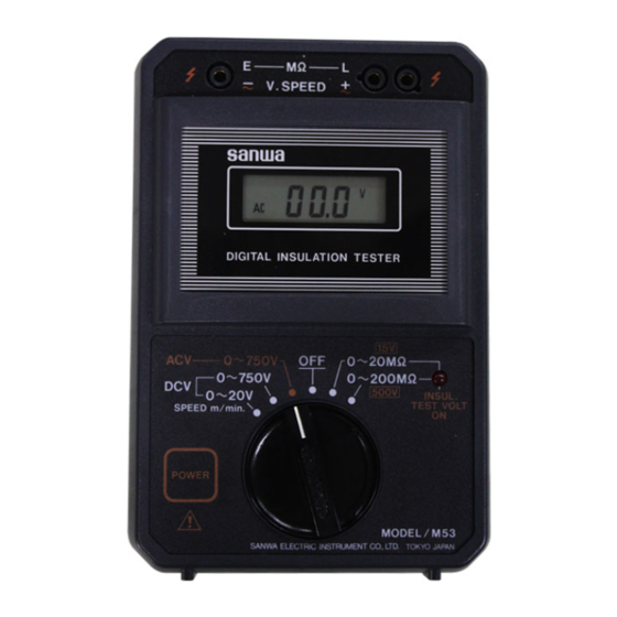
[3]外観および各部名称 ( 1 ) ( 2 ) ( 5 ) ( 3 ) ( 4 ) ( 6 ) 赤 ( + 〜 ) ( 7 ) 黒 ( − 〜 ) ( 8 ) 黒 ( 1 ) 測定端子(絶縁抵抗、 交流電圧、 直流電圧共通) ( 5 ) 絶縁抵抗測定電圧印加表示ランプ(赤色... -
Page 8: 4]測定方法
[4]測定方法 4−1 測定前の準備 警 告 安全にご使用いただくため、本器を使用する前には必ず本器の 外観および、付属品の点検を入念に行ってください。 ①落下等による損傷がないかよく点検してください。 ②付属のテストリード線の絶縁被覆が損傷していたり、芯線が 露出している場合は感電の危険性があります。ご使用前に入 念に点検してください。 参考 電源スイッチの動作とオートパワーオフについて 本器の電源スイッチ (POWER)は、各ファンクションとも押す毎 に ON、 OFF が切り換わるオルタネート式の動作となっております。 測定後、 電源スイッチを切り忘れてもオートパワーオフ機能により、 約1分後に自動的に電源が OFF となりますが、内蔵電池の消耗を 防ぐためにも、測定後はできるだけ電源スイッチをもう一度押して OFF にするようにしてください。 4−2 内蔵電池の確認 1)測定端子には何も接続しない状態にしておきます。 2)ファンクション・スイッチを絶縁抵抗測定レンジの 500 V また は 15 V レンジに切り換えます。 3)測定用 POWER スイッチを押します。 4)絶縁抵抗測定電圧印加表示赤色ランプ(INSUL. TEST VOLT ON)が点灯し、第1図のように表示されれば内蔵電池は正常 です。... -
Page 9: 4−3 内蔵電池の交換
5)POWER ON により、INSUL. TEST VOLT ON ランプが点灯せ ず、表示部に何も表示されない場合は、電池が完全に消耗して いるか、電池が入っていないことが考えられますので、リア ケース裏面の電池蓋を取り外し、 下記の4−3内蔵電池の交換 の項を参照の上、新しい電池を装着してください。 6)電池は入っているが、同様に INSUL. TEST VOLT ON ランプ が点灯せず表示部に何も表示されない場合は、電池端子金具の 接触不良も考えられますので、リアケース裏面の電池蓋を取り 外し、電池と端子金具の接触を点検してください。 7)POWER ON により、INSUL. TEST VOLT ON ランプは点灯す るが、表示部左下部に第2図のような「B」マークが表示され た場合は、内蔵電池の消耗を意味しますので新しい電池と入れ 換えてください。 第2図 4−3 内蔵電池の交換 1)ファンクション・スイッチを中央の OFF にセットします。 警 告 電池の交換にあたっては、ファンクション・スイ ッチが OFF の 位置にあることを必ず確認してから行ってください。 2)電池交換は次頁の第3図を参照の上行ってください。 3)まず、リアケース裏面の電池蓋の止めネジを取り外し、上部中 央(第3図 A )の四角凸部分を指で押しながら下部へスライド させますと電池蓋がはずれますので、 (第3図 B )の指示通り 電池極性を間違えないよう正しく装着してください。 4)装着確認後、再び電池蓋を元の通りリアケースに挿入し、止め ネジで固定します。... -
Page 10: 4−4 絶縁抵抗の測定(Mω
単 3 型 1.5 V 電池 (6 個) 電池蓋 押しつつ スライド φ3 mm 止めネジ 第3図 電池蓋 電池の極性配置 ● ● 注 意 ①電池は必ず指定のもの(単三形アルカリ電池)を使用してく ださい。 ②電池は性能劣化防止のため、全部同時に新品をご使用くださ い。 4−4 絶縁抵抗の測定(MΩ) 警 告 ①絶縁抵抗測定レンジで POWER ON(INSUL. TEST VOLT ON 表示ランプ点灯)の状態では、E − L 端子間に 500 V または 15 V が印加されており、危険ですので測定端子に接続された... - Page 11 1)ファンクション・スイッチを被測定対象に合わせて 500 V また は 15 V に切り換えます。 2)第4図のように黒色テストリード線の黒色プラグを左側の E 端 子に、赤色テストリード線の橙色プラグを右側の L 端子にそれ ぞれ差し込み、黒色テスト棒の先端にピン接続用クリップリー ド線を接続します。 黒 赤 第4図 3)被測定点の一方に黒色クリップを接続し、他の測定点に赤色テ スト棒の先端を当てて、 測定用 POWER スイッチを押しますと、 絶縁抵抗測定電圧印加表示ランプ(INSUL. TEST VOLT ON) が点灯し、表示部には求める抵抗値が指示されます。 4)被測定物が 500 V で 200 MΩ 以上、 15 V で 20 MΩ 以上のときは、 測定端子間オープンのときと同様、 5 頁[4] 4 − 2 内蔵電池の確 認の項における第1図のような入力オーバー表示状態となりま す。...
-
Page 12: 4−5 交流電圧の測定(Acv
参考 測定中「B」マークが表示された場合について 500 V レンジにて絶縁抵抗測定中、指示値が極端に小さいときバッ テリ・アラームの「B」マークが表示されることがあります。 これは測定抵抗値が極端に小さいときは電源消費電流が大きく、電 池の消耗による容量不足より、内部動作電圧が規定電圧値以下に低 下し、この「B」マークが表示される状態となります。 このような場合は電池消耗の時期と判断し、新しい電池に交換して ください。 4−5 交流電圧の測定(ACV) 警 告 ① ACV レンジの最大許容入力電圧は 750 V までであり、それを 超える電圧は絶対に入力しないでください。 ② AC 25 VRMS 以上の電圧は人体に危険です。 測定にあたっては十分ご注意ください。 ③測定中はファンクション・スイッチを絶対に切り換えないで ください。 ④絶対に濡れた手では測定しないでください。 1)ファンクション・スイッチを ACV に切り換えます。 2)第5図のように黒色テストリード線の黒色プラグを左側の − 〜 端 子に、赤色テストリード線の橙色プラグを + 〜 端子にそれぞれ接 続します。... -
Page 13: 4−6 直流電圧の測定(Dcv
3)測定用 POWER スイッチを押し、 POWER ON の状態で赤、黒 テストリード線の先端を被測定点に接続すると、表示部に求め る電圧値が指示されます。 4)測定が終了しましたら、測定用 POWER スイッチをもう一度押 して POWER OFF にするか、ファンクション・スイッチを OFF の位置に切り換えてください。 4−6 直流電圧の測定(DCV) 警 告 ① DCV レンジの最大許容入力電圧は 750 V までであり、それ を超える電圧は絶対に入力しないでください。 ② DC 60 V 以上の電圧は人体に危険です。 測定にあたっては十分ご注意ください。 ③測定中はファンクション・スイッチを絶対に切り換えないで ください。 ④絶対に濡れた手では測定しないでください。 1)被測定電圧のレベルに応じてファンクション・スイッチの設定 をしますが、未知の電圧値の場合は先ず DCV の 0 〜 750 V 側 に切り換えます。... -
Page 14: 4−7 速度(M/Min)の測定
4−7 速度(m/min)の測定 1)測定方法は直流電圧(DCV)のときと同じですが、ファンク ション・スイッチを DCV の 0 〜 20 V に設定します。 2)第6図のように、別売品の SE − 9000 形速度計からのアナログ 出力用コードの◯ + 側赤色プラグを本器 L 端子の右側に、◯ − 側黒 色プラグを E 端子にそれぞれ接続します。 3)測定用 POWER スイッチを押しますと速度計からのアナログ出 力値が mV で表示されますので、この数値をそのまま m/min と して読み取ります。 SE − 9000 アナログ出力 へ 第6図 [5]保守管理について ... -
Page 15: 5−2 校 正
1)落下などにより、本器の外観が損傷していないか? 2)テストリードは ・入力端子にプラグを差し込んだとき緩みがないか? ・テストリードのコード部分が損傷していないか? ・テストリードのどこかの箇所から芯線が露出していないか? 3)ファンクション・スイッチつまみに上部から強い圧力をかけて はいないか?(スイッチの接触不良の原因となる) 以上の項目に該当する場合はそのまま使用せず、修理または新 しいものと交換してください。 5−2 校 正 警 告 安全と確度の維持のため1年に1回以上は点検・校正を実施し てください。 なお、点検・校正については販売代理店または発売元にお問い 合わせください。 5−3 保管について 注 意 ①パネル、リアケースなどは揮発性溶剤や熱に弱いため、シン ナーやアルコールなどで拭いたり、高熱を発生するものの近 くには置かないようにしてください。 お手入れをする場合は、乾いた柔らかい布などで軽く拭き取 るようにしてください。 ②振動の多い場所や落下のおそれのある場所には保管しないで ください。 ③直射日光下や極端な高温、低温そして多湿および、有毒ガス が発生するような場所での保管は避けてください。 ④本器を使用しないときは、ファンクション・スイッチを必ず OFF の位置にセットしておいてください。 ⑤長時間使用されない場合は、内蔵電池は必ず抜いて保管して ください。 − 12 −... -
Page 16: 6]アフターサービスについて
[6]アフターサービスについて 6−1 保証期間について 本製品の保証期間は、お買い上げの日より 3 年間です。 ただし、 日本国内で購入し日本国内でご使用いただく場合に限ります。 また、製品本体の確度は 1 年保証、製品付属の電池、ヒューズ、テス トリード等は保証対象外とさせていただきます。 6−2 修理について 1)修理依頼の前に次の項目をご確認ください。 ・内蔵電池の容量はありますか?装着の極性は正しいですか? ・テストリードは断線していませんか? ・内蔵ヒューズは切れていませんか? 2)保証期間中の修理 ・保証書の記載内容によって修理させていただきます。 3)保証期間経過後の修理 ・修理費用や輸送費用が製品価格より高くなる場合もあります ので、事前にお問い合わせください。 ・本品の補修用性能部品の最低保有期間は、製造打切後 6 年間 です。この補修用性能部品保有期間を修理可能期間とさせて いただきます。ただし購買部品の入手が製造会社の製造中止 等により不可能になった場合は、保有期間が短くなる場合も ありますのでお含みおきください。 − 13 −... -
Page 17: 6−3 お問い合わせ先
きます。 [送り先] 三和電気計器株式会社・羽村工場サービス課 〒205-8604 東京都羽村市神明台 4-7-15 TEL(042) 554-0113 6−3 お問い合わせ先 三和電気計器株式会社 本 社 :TEL(03) 3253-4871 / FAX(03) 3251-7022 大阪営業所 : TEL(06) 6631-7361 / FAX(06) 6644-3249 製品についての問い合わせ: 0120-51-3930 受付時間 9:30 〜 12:00 13:00 〜 17:00 (土日祭日および弊社休日を除く) ホ ー ム ペ ー ジ:http://www.sanwa-meter.co.jp − 14 −... -
Page 18: 7]仕 様
[7]仕 様 7−1 絶縁抵抗測定部 1)測定電圧 DC 500 V、DC 15 V 2 レンジ式 2)測定電圧・ DC 500 V レンジ JIS C 1302 ( 1994) 規格に準拠 電流特性 測定端子開放 600 V (+ 20 %max.) 500 kΩ にて> 500 V を保証 測定端子短絡電流 1.6 mA max. DC 15 V レンジ > 1 MΩ にて 15 V±10 % 3)測定範囲 DC 500V レンジ 0 〜 2 MΩ/1 MΩ 〜 20 MΩ/10 MΩ 〜 200 MΩ 3 オートレンジ切り換え式 DC 15 V レンジ 0 〜 2 MΩ/1 MΩ 〜 20 MΩ 2 オートレンジ切り換え式... -
Page 19: 7−4 共通仕様
175 ( H ) ×115 ( W ) ×55 ( D ) mm 約 600 g 12)寸法・重量 7−5 付属品 1)橙色プラグ付赤色テストリード線(L、 + 〜 端子) 1 本 2)黒色プラグ付黒色テストリード線(E、 − 〜 端子) 1 本 3)ピン接続用クリップ付リード線 1 本 以上3本セット:TL − M54 4)取扱説明書 1 部 5)携帯ケース:C − M53(コードケース込み) 1 個 説明中の仕様は性能向上のため、お断わりなく変更することが ありますのでご了承ください。 − 16 −... - Page 20 保証書 ご氏名 型 名 様 製造No. ご住所 この製品は厳密なる品質管理を経てお 〒 届けするものです。 本保証書は所定項目をご記入の上保管 していただき、アフターサービスの際 ご提出ください。 ※下記の保証規定をよくお読みください。 ※本保証書は再発行はいたしませんの で大切に保管してください。 保証期間 ご購入日 年 月より 3 年間 本社=東京都千代田区外神田2−4−4 ・ 電波ビル (製品の確度については 1 年間) 郵便番号=101-0021・電話=東京 (03) 3253−4871 ( 代) 保証規定 保証期間内に正常な使用状態のもとで、 万一故障が発生した場合には無償で修理いたします。 但し、保証期間内であっても下記の場合には保証の対象外とさせていただきます。 記 1. 取扱説明書に基づかない不適当な取扱い (保管状態を含む) または使用による故障 2. 弊社以外による不当な修理や改造に起因する故障 3. 天災などの不可抗力による故障や損傷、および故障や損傷の原因が本計器以外の事由に...
- Page 21 DIGITAL INSULATION METER WITH VOLTAGE & SPEED RANGE INSTRUCTION MANUAL...
- Page 22 [1] Safety Precautions --- Be sure to read before use. --- Be sure to read carefully the information under “ WARNING” and “ CAUTION” in this manual in order to prevent human injuries, electric shock and damage to the instrument as well as other equipment. 1-1 Warning Markings and Other Symbols The symbols and their meanings used with the instrument and in this manual are as described below.
- Page 23 1-2 Warning Messages for Safety WARNING 1. Check the measurement type (insulation resistance, DC or AC voltage) before measurement and select the appropriate function for it. 2. Do not apply a voltage or signal exceeding the specified maximum allowable input. (For the maximum allowable input voltage value, see section 1-3 on the next page.) 3.
- Page 24 This device is a digital insulation resistance tester, with DCV & ACV measurement functions. In addition to that, it also has optional speed measurement function (Sanwa speed meter SE-9000 is necessary to use this function), that enables to read output voltage value directly as a speed value. 2-2 Features 1.
- Page 25 [3] Appearance and Appellation (1) Measurement terminal (Insulation (5) Insulation resistance measurement resistance, ACV, DCV) voltage input indication lamp (red LED) (2) LCD (6) Red test lead (L, side) (3) Function switch (7) Black test lead (E, side) (4) Power switch (8) Clip lead for connecting pin −...
- Page 26 [4] Measuring Methods 4-1 Preparations WARNING For safe use of the instrument, check its appcarance and associated accessories carefully before use. 1. Check for damage due to dropping, etc. 2. There is a risk of electric shock if the insulation coating of a test lead or its conductor wire is exposed.
- Page 27 5. If the INSUL. TEST VOLT ON indicator does not light and the LCD shows nothing even when the POWER switch is pressed to ON, the batteries may be exhausted completely, or no battery has been loaded. In this case, remove the battery cover on the rear case and insert new batteries as described in section 4-3, “Replacing the Built-in Batteries”...
- Page 28 1.5 V battery Battery cover Press and slide φ3 mm screw ◯ ◯ Fig. 3 CAUTION 1. Always use the specified batteries (LR6 batteries). 2. To prevent performance degradation, replace all six batteries with six brand-new ones when the time comes to replace batteries.
- Page 29 1. Set the function switch according to the measurement object, to 500 V or 15 V. 2. Connect the black plug of the black test lead to the E terminal on the left and the amber plug of the red test lead to the L terminal on the right as shown in Fig.
- Page 30 NOTE: In Case the “ B ” Marking is Displayed During Measurement When the resistance measurement value in an insulation test is extremely small, the LCD sometimes shows the “B” marking which is usually used as the battery alarm indicator. In the present case, the “B”...
- Page 31 3. Press the POWER switch to ON, connect the black clip to a measuring point on the measurement object, and apply the tip of the red test rod to another measuring point. The LCD will show the measurement voltage value. 4.
- Page 32 4-7 Speed(m/min) measurement 1. The measurement method is the same as DCV measurement, but set the function switch to DCV 0-20 V. 2. As shown in Figure 6, connect optional cable of SE-9000 (speed meter), positive red plug to the right side of L terminal, and negative black plug to E terminal.
- Page 33 1. Check that the external finish of the instrument is not damaged due to dropping etc. 2. Check the test leads to ensure that · a plug is not loose when it is inserted into a terminal; · the test lead coating is not damaged; ·...
- Page 34 Sanwa authorized agent or distributor. Sanwa reserves the right to inspect all warranty claims to determine the extent to which the warranty policy shall apply. This warranty shall not apply to fuses, disposables batteries, or any product or parts, which have been subject to one of the following causes: 1.
- Page 35 Please contact Sanwa authorized agent / distributor / service provider, listed in our website, in your country with above information. An instrument sent to Sanwa / agent / distributor without those information will be returned to the customer. Note: 1. Prior to requesting repair, please check the following: Capacity of the built-in battery, polarity of installation and discontinuity of the test leads.
- Page 36 [7] Specifications 7-1 Insulation Resistance Measuring Block 1. Rated voltage DC 500 V, DC 15 V, 2 ranges 2. Measuring voltage/current characteristics DC 500 V range When measuring terminals are open 600 V (+20 % max.) When measuring terminals are shorted Approx. 1.6 mA max. DC 15 V range : 15 V±10 % at 1 MΩ...
- Page 37 3. Alligator clip adapter x 1 Set of the avobe 3 test leads: TL-M54 4. Instruction manual x 1 5. Carrying case C-M53 (with cord case) x 1 The specifications in this manual may be subject to change for performance improvement without notice.
- Page 38 MEMO...
- Page 39 MEMO...
- Page 40 本社=東京都千代田区外神田 2−4−4・電波ビル 郵便番号=101-0021・電話=東京 (03) 3253−4871 (代) 大阪営業所=大 阪市浪速区恵美須西2 −7 −2 郵便番号=556-0003・ 電話 = 大阪 (06) 6631−7361 ( 代) Dempa Bldg., 4-4 Sotokanda 2-Chome, Chiyoda-Ku, Tokyo, Japan 植物油インキを使用しています。 05-1710 2040 2040...
Need help?
Do you have a question about the M53 and is the answer not in the manual?
Questions and answers