Table of Contents
Advertisement
Quick Links
Advertisement
Table of Contents

Related Manuals for Extreme Networks WM-4T1i WAN


Summary of Contents for Extreme Networks WM-4T1i WAN
- Page 1 WAN Module Installation and User Guide (Includes WM-4T1i Module Installation and User Guide) Extreme Networks, Inc. 3585 Monroe Street Santa Clara, California 95051 (888) 257-3000 http://www.extremenetworks.com Published: December, 2001 Part number:100095-00 rev02...
- Page 2 SummitGbX, SummitRPS, and the Extreme Networks logo are trademarks of Extreme Networks, Inc., which may be registered or pending registration in certain jurisdictions. The Extreme Turbodrive logo is a service mark of Extreme Networks, which may be registered or pending registration in certain jurisdictions. Specifications are subject to change without notice.
-
Page 3: Table Of Contents
Contents Preface Introduction Conventions Related Publications Installing the WAN Module Overview Installing the WAN Module Ports and Connectors Installing the WAN Module Software Configuring the WAN Physical Link Overview Configuring WAN Physical Links WAN Module Installation and User Guide Terminology Module LEDs Red, Blue, and Yellow Alarms Cable length... - Page 4 Monitoring WAN Physical Links Configuring PPP and MLPPP Overview Multilink PPP and Multilink Groups Configuring a PPP/MLPPP Link Monitoring PPP/MLPPP Links PPP/MLPPP Configuration Examples Industry Canada Certification FCC Certification Index Index of Commands Linecoding Receiver Gain SNMP Alerts Timeslots Yellow Alarms WAN Port Configuration Commands Loopback Near-end Loopback Modes...
-
Page 5: Preface
This Preface provides an overview of this guide, describes guide conventions, and lists other publications that may be useful. Introduction This guide provides the required information to install the WM-4T1i, WM-4E1i, and WM-1T3i WAN modules in an Alpine 3800 series switch from Extreme Networks and perform the initial module configuration tasks. -
Page 6: Terminology -Vi
Terminology When features, functionality, or operation is specific to one of the WAN modules, the specific module name is used. Explanations about features and operations that are the same for both of the WAN modules simply refer to the product as the “module.” Conventions Table 1 and Table 2 list conventions that are used throughout this guide. - Page 7 Table 2: Text Conventions (continued) Convention Words in italicized type WAN Module Installation and User Guide Description Italics emphasize a point or denote new terms at the place where they are defined in the text. Conventions...
-
Page 8: Related Publications -Viii
• ExtremeWare Software User Guide • Alpine 3800 Series Switch Hardware Installation Guide • Alpine Module Installation Note Documentation for Extreme Networks products is available on the World Wide Web at the following location: http://www.extremenetworks.com/ viii WAN Module Installation and User Guide... -
Page 9: Installing The Wan Module
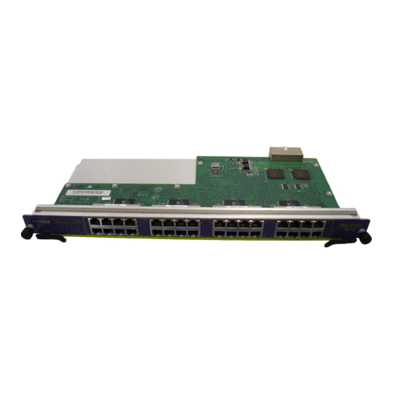
T1/E1 physical links. The modules also have two general purpose 10/100 Mbps Ethernet ports. WM-4T1i is the designation of the T1 version, and WM-4E1i is the designation of the E1 version. Also included among the WAN modules is a one-port T3 module, designated WM-1T3i, that uses PPP for its traffic. - Page 10 Installing the WAN Module Installing the WAN Module All Alpine ™ 3800 series switch module cards (SMMi modules and I/O modules) are hot-swappable. You do not need to power off the system to remove or insert a module card. Caution: Service to Alpine modules should be performed by trained service personnel only.
-
Page 11: Ports And Connectors
Internal loopback ports are marked with the notation “iL” when displayed on the command line or with ExtremeWare Vista Web access. The WM-4E1i module has four E1 ports in place of the T1 ports found in the WM-4T1i module. It is identical in all other respects. -
Page 12: Module Leds
Installing the WAN Module Module reset Module status T3 port 10/100 Mbps ports LEDs 38_WM1T3i Figure 1-2: WM-1T3i Module The WM-1T3i module has one T3 port, consisting of a two BNC connectors, one for the transmit path and one for the receive path. The module also has two general purpose 10/100 Ethernet ports. - Page 13 Table 1-1 describes the LED behavior on the WAN modules. Table 1-1: WAN Module LEDs Color Status Amber Green Diag Green (blinking) WAN port Amber (1-4)T1/E1 (1)T3 Amber (blinking rapidly) Amber (blinking slowly) Green Alternating green and amber Green (blinking slowly) Green (blinking rapidly)
-
Page 14: Installing The Wan Module Software
New SMMi images and module images are released together, so if you upgrade both at the same time, you will be certain to have compatible images. If this is not feasible, see the Extreme Networks customer support website for compatibility information. - Page 15 Installing the WAN Module Software The module can store up to two images; a primary and a secondary. When you download a new image, you must select into which image space (primary or secondary) the new image should be placed. If not indicated, the primary image space is used. You can select which image the switch or module will load on the next reboot by using the following command: use image {slot <slot>} [primary | secondary]...
- Page 16 Installing the WAN Module WAN Module Installation and User Guide...
-
Page 17: Configuring The Wan Physical Link
Configuring the WAN Physical Link This chapter covers the following topics: • Configuring WAN Physical Links on page 2-2 • Monitoring WAN Physical Links on page 2-8 Overview In this document, WAN refers to either T1, E1, or T3 technologies. T1 is a mature technology originally developed for voice telephone transmission. -
Page 18: Red, Blue, And Yellow Alarms
Configuring the WAN Physical Link Red, Blue, and Yellow Alarms WAN links have error detection built into the link hardware. The hardware can detect different types of errors, labeled red, blue and yellow alarms. A red alarm occurs when the signal is lost or an out of frame error occurs. An out of frame error can be caused when the framing type configured for the local interface does not match the framing type of the incoming signal or when the incoming signal does not contain a framing pattern. -
Page 19: Cable Length
Configuring WAN Physical Links • Timeslots (E1) • Yellow Alarms (T1) Cable length Longer cable lengths cause greater losses for signals, so transmitter hardware must transmit at a higher level to transmit data successfully. However, too high a signal level can cause crosstalk from one cable to another. -
Page 20: Clock Source
Configuring the WAN Physical Link Clock Source A clock is used to synchronize data transmission on the line. Generally, one end of the link provides the master clock, and the other end of the link recovers the clock from the signal on the line. -
Page 21: Inband Loopback Detection
Configuring WAN Physical Links config ports <portlist> e1 framing [crc4 | no-crc4] The framing choices for T3 are C-bit and M13. To choose the T3 framing scheme, use the following command: config ports <portlist> t3 framing [c-bit | m13] Inband Loopback Detection When inband loopback detection is enabled, a specific sequence of data in the signal payload from the remote end of the T1 link will cause the local end to enter network line loopback mode and send any received signal back to the remote end. -
Page 22: Timeslots
Configuring the WAN Physical Link send an SNMP alert to the SMMi in the switch when red, yellow, or blue alarms are detected. If the module is configured to send SNMP alerts, and the switch is configured to send SNMP trap messages, then the switch will send a message to any SNMP trap receivers that have been configured. -
Page 23: Wan Port Configuration Commands
alarm generation and detection is both. To configure yellow alarms, use the following command: config ports <portlist> t1 yellow [detection | generation | both | off] WAN Port Configuration Commands Table 2-1 describes the commands used to configure a WAN port. Table 2-1: WAN Port Configuration Commands Command config ports <portlist>... -
Page 24: Monitoring Wan Physical Links
Configuring the WAN Physical Link Table 2-1: WAN Port Configuration Commands (continued) Command config ports <portlist> e1 timeslots <timeslots> config ports <portlist> t1 yellow [detection | generation | both | off] Monitoring WAN Physical Links T1, E1, and T3 devices have a built-in facility designed for troubleshooting the physical link, called loopback. -
Page 25: Near-End Loopback Modes
Monitoring WAN Physical Links to the remote end. At the remote end, the process is reversed as the framing bits are discarded and the data stream is passed to the remote system. Loopback can be enabled on the near-end of a WAN link, but only the T1 and T3 modules can enable loopback on the far-end of a link. - Page 26 Configuring the WAN Physical Link Local Loopback Mode. When the local port is enabled for local loopback, the local data stream goes into the framer and the framing bits are inserted into the data, but the data is not transmitted to the remote end. Instead, it is sent back through the local framer, the framing bits are discarded, and the original data is returned.
-
Page 27: Far-End Loopback Modes
Far-End Loopback Modes The far-end of T1 links can be enabled for the following two loopback modes: • Remote Line • Remote Payload The far-end of T3 links can be enabled for the following loopback mode: • Remote Line The remote line mode reflects the received signal back to the near-end. The remote payload mode reflects the data and regenerates the framing information back to the near-end. -
Page 28: Enabling Loopback Mode
Configuring the WAN Physical Link Local WAN Port Remote WAN Port Data out Data in Data in Data out Framer Framer XM_015 Figure 2-6: Remote payload loopback mode Remote Payload Loopback Mode. When the local port is enabled for remote payload loopback mode, it sends a request to the remote end to enter the equivalent of network payload loopback mode. -
Page 29: Wan Port Monitoring Commands
WAN Port Monitoring Commands Table 2-2 describes the commands used to monitor a WAN port. Table 2-2: WAN Port Monitoring Commands Command disable ports <portlist> [t1 | e1 | t3] loopback enable ports <portlist> [t1 | e1 | t3] loopback [local | network line] enable ports <portlist>... - Page 30 Configuring the WAN Physical Link 2-14 WAN Module Installation and User Guide...
-
Page 31: Configuring Ppp And Mlppp
Configuring PPP and MLPPP This chapter covers the following topics: • Multilink PPP and Multilink Groups on page 3-2 • Configuring a PPP/MLPPP Link on page 3-3 • Monitoring PPP/MLPPP Links on page 3-6 • PPP/MLPPP Configuration Examples on page 3-7 Overview Point-to-Point Protocol (PPP) is used across the entire range of communication speeds and devices found on the internet. -
Page 32: Multilink Ppp And Multilink Groups
Configuring PPP and MLPPP Typically, you would create a multilink group, configure the multilink group by adding T1 or E1 ports and configuring PPP/MLPPP parameters, add the multilink group to a VLAN, and finally, enable the multilink group. For a T3 port, you would configure its PPP parameters and add it to a VLAN. Multilink PPP and Multilink Groups Each multilink PPP group is given a name, up to 16 characters in length. -
Page 33: Configuring A Ppp/Mlppp Link
<groupname> Authentication By default, no authentication is configured on PPP links since the WM-4T1i module will typically be used with leased lines—where both sides of the link are controlled and authentification is not required. If authentication is needed, the WM-4T1i module supports either PAP or CHAP. -
Page 34: Ppp Link Username
Configuring PPP and MLPPP config ppp authentication [off | chap | pap | chap-pap] [ports <portlist> | multilink <groupname>] PPP Link Username When the local end of a link initiates a PPP connection, the local end must send the appropriate authentication information. For PAP it sends the username and password, for CHAP it sends the username and must respond correctly to the challenge, and for no authentication it sends nothing. -
Page 35: Ppp/Mlppp Configuration Commands
Routed packets are transported across a PPP/MLPPP link using IP Control Protocol (IPCP), described in RFC 1332. This is the encapsulation that is familiar to most users of PPP. The routed packets do not contain Ethernet headers so cannot preserve VLAN tags. -
Page 36: Monitoring Ppp/Mlppp Links
Configuring PPP and MLPPP Table 3-1: PPP/MLPPP Configuration Commands (continued) Command config vlan <vlan> add multilink <groupname> config vlan <vlan> delete multilink <groupname> create account pppuser <name> {encrypted} {<password>} create multilink <groupname> delete multilink <groupname> delete account pppuser <username> disable multilink <groupname> enable multilink <groupname>... -
Page 37: Ppp/Mlppp Configuration Examples
Table 3-2: PPP/MLPPP Show Commands (continued) Command show ppp {<portlist>} {detail} show accounts pppuser 1. To display alarm status for T3 links, use the 2. To display error statistics for T3 links, use the PPP/MLPPP Configuration Examples The following examples show how to configure multilink groups. Configuring a Bridged PPP/MLPPP Link Example The following example shows how to configure a BCP-encapsulated multilink group. -
Page 38: Configuring A Routed Ppp/Mlppp Link Example
Configuring PPP and MLPPP VLAN alpha tag = 1001 Multilink bcp_example encapsulation = BCP Switch #1 Figure 3-1: BCP multilink example create vlan alpha config alpha tag 1001 create multilink bcp_example config ports 4:1-4:3 t1 clocksource internal config bcp_example add ports 4:1-4:3 tag config alpha add multilink bcp_example enable bcp_example Configuring a Routed PPP/MLPPP Link Example... - Page 39 Switch #1 Figure 3-2: IPCP multilink example create vlan beta config beta tag 1001 config beta ipaddress 10.10.10.1/24 create multilink ipcp_example config ipcp_example add ports 4:1-4:3 tag config ppp ipcp on ports 4:1-4:3 config beta add multilink ipcp_example enable ipcp_example WAN Module Installation and User Guide VLAN beta tag = 1001 IP address = 10.10.10.1/24...
- Page 40 Configuring PPP and MLPPP 3-10 WAN Module Installation and User Guide...
-
Page 41: Industry Canada Certification
Safety Information Industry Canada Certification The Industry Canada label identifies certified equipment. This certification means that the equipment meets the telecommunications network protective, operational, and safety requirements as prescribed in the appropriate Terminal Equipment Technical Requirements documents. The Department does not guarantee the equipment will operate to the user’s satisfaction. -
Page 42: Fcc Certification
There are no repairs that can be made by the customer to the WM-4T1i. WAN Module Installation and User Guide... - Page 43 Index Numerics 802.1p 802.1Q alarms alternate mark inversion (AMI) AMI linecoding authentication B8ZS linecoding BCP encapsulation bipolar eight zero suppression (B8ZS) blue alarms bridged PPP links cable length C-bit T3 line framing Challenge Handshake Authentication Protocol (CHAP) CHAP clock source configuring E1 port encapsulation...
- Page 44 T1 port linecoding B8ZS loopback detection M13 T3 line framing MLPPP multilink group adding to VLAN Multilink PPP (MLPPP) Password authentication protocol (PAP) Point-to-Point Protocol (PPP) PPP links bridged routed PPP user accounts PPP username PPP/MLPPP configuration commands (table) red alarms RFC 1332 RFC 2878 routed PPP links...
- Page 45 Index of Commands config multilink add ports config multilink delete ports config ports e1 clock source config ports e1 framing config ports e1 receivergain config ports e1 snmp alert config ports e1 timeslots config ports t1 cablelength config ports t1 clock source config ports t1 fdl config ports t1 framing config ports t1 lbdetect...
- Page 46 show ports e1 info show ports e1 stats show ports stats show ports t1 alarms show ports t1 configuration show ports t1 errors show ports t1 info show ports t1 stats show ports t3 errors show ports t3 info show ports t3 stats show ppp unconfig ppp ii - Index of Commands...
Need help?
Do you have a question about the WM-4T1i WAN and is the answer not in the manual?
Questions and answers