
Related Manuals for Extreme Networks WM-4T1i


Summary of Contents for Extreme Networks WM-4T1i
- Page 1 WM-4T1i Module Installation and User Guide Extreme Networks, Inc. 3585 Monroe Street Santa Clara, California 95051 (888) 257-3000 http://www.extremenetworks.com Published: June 2001 Part number: 100095-00 Rev. 01...
- Page 2 SummitGbX, SummitRPS, and the Extreme Networks logo are trademarks of Extreme Networks, Inc., which may be registered or pending registration in certain jurisdictions. The Extreme Turbodrive logo is a service mark of Extreme Networks, which may be registered or pending registration in certain jurisdictions. Specifications are subject to change without notice.
-
Page 3: Table Of Contents
Introduction Conventions Related Publications Installing the WM-4T1i Module Overview Installing the WM-4T1i Module Ports and Connectors Installing the WM-4T1i Module Software Configuring the T1 Physical Link Overview Configuring T1 Physical link WM-4T1i Installation and User Guide WM-4T1i Module LEDs Alarms... - Page 4 Enabling Loopback Mode Disabling Loopback Mode T1 Port Monitoring Commands Authentication PPP Link Username PPP User Accounts Encapsulation PPP/MLPPP Configuration Commands Configuring a Bridged PPP/MLPPP Link Example Configuring a Routed PPP/MLPPP Link Example 2-10 2-10 2-10 WM-4T1i Installation and User Guide...
-
Page 5: Preface
This Preface provides an overview of this guide, describes guide conventions, and lists other publications that may be useful. Introduction This guide provides the required information to install the WM-4T1i module in an Alpine 3800 series switch from Extreme Networks and perform the initial module configuration tasks. -
Page 6: Conventions
If you must press two or more keys simultaneously, the key names are linked with a plus sign (+). Example: Press [Ctrl]+[Alt]+[Del]. Words in italicized type Italics emphasize a point or denote new terms at the place where they are defined in the text. WM-4T1i Module Installation and User Guide... -
Page 7: Related Publications
• ExtremeWare Software User Guide • Alpine 3800 Series Switch Hardware Installation Guide • Alpine Module Installation Note Documentation for Extreme Networks products is available on the World Wide Web at the following location: http://www.extremenetworks.com/ WM-4T1i Module Installation and User Guide... - Page 8 WM-4T1i Module Installation and User Guide...
-
Page 9: Installing The Wm-4T1I Module
• Installing the WM-4T1i Module Software on page 1-5 Overview The Extreme Networks WM-4T1i module is an four-port T1 module that can be configured to use Multilink PPP to aggregate Ethernet traffic across multiple T1 physical links. The module has two 10/100 Mbps Ethernet ports. - Page 10 As the module begins to seat in the chassis, the ejector/injector handles will begin to close. 6 To secure the module in the chassis, close the ejector/injector handles by pushing them toward the center of the module card, and tighten the screws using a #2 Phillips-head screwdriver. WM-4T1i Module Installation and User Guide...
-
Page 11: Ports And Connectors
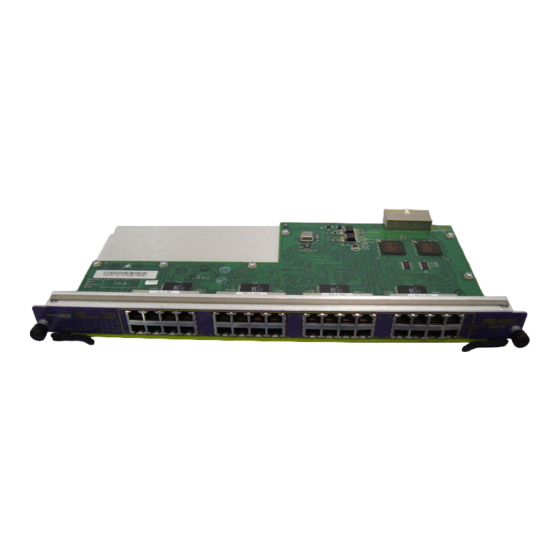
LEDs Figure 1-1: WM-4T1i Module The WM-4T1i module has four T1 ports and two 10/100 Ethernet ports. The WM-4T1i also has six internal loopback ports. Internal loopback ports allow you to configure bi-directional rate-limiting without tying up any of the external ports for ingress rate shaping. - Page 12 Installing the WM-4T1i Module Figure 1-2: WM-4T1i LEDs Table 1-1 describes the LED behavior on the WM-4T1i module. Table 1-1: WM-4T1i Module LEDs Color Status Amber Green Diag Green (blinking) T1 port (1-4) Amber Rapidly blinking amber Slowly blinking amber...
-
Page 13: Installing The Wm-4T1I Module Software
Installing the WM-4T1i Module Software Once the WM-4T1i module is installed in the chassis, you must download an image file to the module. The image file contains the executable code that runs on the module. As new versions of the image are released, you should upgrade the software running on your module. - Page 14 Installing the WM-4T1i Module use image [primary | secondary] WM-4T1i Module Installation and User Guide...
-
Page 15: Configuring The T1 Physical Link
If you must connect to a line controlled by another organization, you will need to configure the line to correspond with the settings at the other end. You can specify the following parameters: • Alarms • Cable length WM-4T1i Module Installation and User Guide... -
Page 16: Alarms
Longer cable lengths cause greater loss for the T1 signal, so the transmitter hardware must transmit at a higher level to transmit data successfully. However, too high a signal level can cause crosstalk from one cable to another. The config ports t1 WM-4T1i Module Installation and User Guide... -
Page 17: Clock Source
Facility data link (FDL) uses twelve bits in the ESF frame to signal information about line and connection status. Since FDL is only meaningful for ESF framing, FDL settings WM-4T1i Module Installation and User Guide command: -22.5 db, -15 db, -7.5 db, 0 db, 133 feet, 266 feet, 399 feet,... -
Page 18: Framing
You can choose from two linecoding standards, bipolar eight zero suppression (B8ZS) or alternate mark inversion (AMI). The default value is B8ZS. To configure linecoding, use the following command: config ports <portlist> t1 linecoding [b8zs | ami] WM-4T1i Module Installation and User Guide... -
Page 19: Yellow Alarms
<portlist> t1 lbdetect [off | inband] config ports <portlist> t1 linecode [b8zs | ami] config ports <portlist> t1 yellow [detection | generation | both | off] WM-4T1i Module Installation and User Guide Configuring T1 Physical link Description Enables and disables alarms. The default setting is on. -
Page 20: Monitoring T1 Physical Link
A message is sent to the far-end to cause it to enter a far-end loopback mode. When loopback is enabled on a T1 port, the green port LED will blink. WM-4T1i Module Installation and User Guide... -
Page 21: Near-End Loopback Modes
Instead, it is sent back through the local framer, the framing bits are discarded, and the original data is returned. This mode tests the local end. WM-4T1i Module Installation and User Guide... -
Page 22: Far-End Loopback Modes
This mode tests the line and the local circuitry from the remote side. Far-End Loopback Modes The far-end of the link can be enabled for the following two loopback modes: • Remote Line • Remote Payload WM-4T1i Module Installation and User Guide... - Page 23 Remote Payload Loopback Mode. When the local port is enabled for remote payload loopback mode, it sends a request to the remote end to enter the equivalent of network payload loopback mode. When the remote end enters loopback mode, the framer at the WM-4T1i Module Installation and User Guide Framer Framer...
-
Page 24: Enabling Loopback Mode
Enable the port to locally loopback, to cause the remote link to loopback, and to stop the loopback. Displays real-time port statistics. Displays real-time port alarms. Displays the port configuration and status. WM-4T1i Module Installation and User Guide... - Page 25 Command show ports {<portlist>} t1 errors [near-end | far-end] [totals | intervals | current] show ports {<portlist>} t1 info WM-4T1i Module Installation and User Guide Monitoring T1 Physical Link Description Displays current and past errors. Displays the port configuration and status.
- Page 26 Configuring the T1 Physical Link 2-12 WM-4T1i Module Installation and User Guide...
-
Page 27: Configuring Ppp And Mlppp
PPP links and properly sequences packets across the multilink group. Typically, you would add a multilink group to a VLAN, configure the multilink group by adding T1 ports and configuring PPP/MLPPP parameters, and finally, enable the multilink group. WM-4T1i Module Installation and User Guide... -
Page 28: Multilink Ppp And Multilink Groups
<groupname> Any changes to an enabled multilink group will not take effect until the the multilink group is restarted. To restart a multilkink group, use the following command: restart multilink <groupname> WM-4T1i Module Installation and User Guide... -
Page 29: Configuring A Ppp/Mlppp Link
<groupname> Authentication By default, no authentication is configured on PPP links since the WM-4T1i module will typically be used with leased lines—where both sides of the link are controlled and authentification is not required. If authentication is needed, the WM-4T1i module supports using PAP or CHAP. -
Page 30: Ppp User Accounts
PPP Bridging Control Protocol (BCP), described in RFC 2878. When the encapsulation is set to BCP, 802.1Q and 802.1p information is preserved and transported across the link. On a WM-4T1i module, a VLAN may only contain one BCP encapsulated link. -
Page 31: Ppp/Mlppp Configuration Commands
<groupname> delete multilink <groupname> delete account pppuser <username> disable multilink <groupname> enable multilink <groupname> WM-4T1i Module Installation and User Guide Configuring a PPP/MLPPP Link Description Adds ports to a multilink group. Removes ports from a multilink group. Sets the authentication method for a PPP link or a MLPPP multilink group. -
Page 32: Monitoring Ppp/Mlppp Links
Displays the configuration of the multilink group. Displays multlink group statistics. Displays T1 error statistics for a multilink group. Shows PPP configurations. Show the PPP accounts on the switch. command is included to show where you might need WM-4T1i Module Installation and User Guide... -
Page 33: Configuring A Routed Ppp/Mlppp Link Example
Configuring a Routed PPP/MLPPP Link Example The following example shows how to configure a IPCP-encapsulated multilink group. The VLAN that contains the IPCP-encapsulated multilink group cannot contain any other ports. WM-4T1i Module Installation and User Guide tag = 1001 Multilink bcp_example encapsulation = BCP... - Page 34 10.10.10.1/24 create multilink ipcp_example config ipcp_example add ports 4:1-4:3 tag config ppp ipcp on ports 4:1-4:3 config beta add multilink ipcp_example enable ipcp_example T1 port 4:1 T1 port 4:2 T1 port 4:3 switch XM_008 WM-4T1i Module Installation and User Guide...
- Page 35 Index Numerics 802.1p 802.1Q alarms alternate mark inversion (AMI) AMI linecoding authentication B8ZS linecoding BCP encapsulation bipolar eight zero suppression (B8ZS) bridged PPP links cable length Challenge Handshake Authentication Protocol (CHAP) CHAP clock source configuring encapsulation T1 port conventions notice icons, Preface text, Preface encapsulation configuring...
- Page 36 Point-to-Point Protocol (PPP) PPP authentication protocol (PAP) PPP links bridged routed PPP user accounts PPP username PPP/MLPPP configuration commands (table) RFC 1332 RFC 2878 routed PPP links SF (Super Frame) T1 line framing T1 port alarms cable length clock source configuration commands (table) configuring framing...
-
Page 37: Index Of Commands
Index of Commands config multilink add ports config multilink delete ports config ports t1 alarms config ports t1 cablelength config ports t1 clock source config ports t1 fdl config ports t1 framing config ports t1 lbdetect config ports t1 linecode config ports t1 yellow config ppp authentication config ppp bcp... - Page 38 ii - Index of Commands...
Need help?
Do you have a question about the WM-4T1i and is the answer not in the manual?
Questions and answers