Table of Contents
Advertisement
Quick Links
INDEX
1. General ................................................................................. 2
2. Safety .............................................................................. 2 - 4
A. Pump type ............................................................................ 5
B. Kinds of dive .................................................................. 5 - 6
C. Inspection ............................................................................. 6
D. Number of single pump elements ...................................... 6
E. Number of double pump elements ..................................... 6
F. Number of cover plates ....................................................... 6
G. Position of drive .................................................................. 7
H. Reservoir .............................................................................. 7
I. Accessories ......................................................................... 7
3. Design ................................................................................... 8
4. Principle of operation .......................................................... 8
5. Specification ........................................................................ 8
6. Installation .................................................................... 9 - 10
7. Start-up ............................................................................... 12
8. Subsequent modifications ................................................ 13
9. Maintenance ............................................................... 13 - 14
10. Fault finding ....................................................................... 14
11. Plates .................................................................................. 15
12. Manufacturer's declaration ............................................... 16
Page 1 of 16
Operating instructions
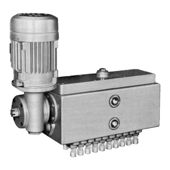
Pump D2
Page
BA_2005_2_GB_D2
Replacement for BA_2005_1_GB_D2
Advertisement
Table of Contents

Related Manuals for Bijur Delimon D2


Summary of Contents for Bijur Delimon D2
-
Page 1: Table Of Contents
Operating instructions Pump D2 INDEX Page 1. General ................. 2 2. Safety ................2 – 4 A. Pump type ................5 B. Kinds of dive ..............5 – 6 C. Inspection ................6 D. Number of single pump elements ........6 E. -
Page 2: General
General Prior to start up, we recommend to read these operating instructions carefully as we do not assume any liability for damages and operating troubles which result from the nonobservance of these operating instructions! Any use beyond the applications described in these operating instructions is considered to be not in accordance with the product’s intended purposes. - Page 3 Safety (continuation) Personnel qualification and training The operating, maintaining, inspecting and erecting personnel must have the appropriate qualification for such work. Area of responsibility, competence and supervision of the personnel have to be regulated by the user. If the personnel do not have the necessary knowledge, they have to be trained and given instructions.
- Page 4 Safety (continuation) Unacceptable modes of operation The operational reliability of the machine supplied is only guaranteed if the machine is used in accordance with its intended purposes as per section 1 - General - of the operating instructions. The limiting values specified in the data sheet must on no account be exceeded.
-
Page 5: Pump Type
ALLGEMEINE PRODUKTMERKMALE • Oil pump • Discharge pressure max. 100 bar • Metered volume 2 x 0.15 cm for double pump element • Metered volume 1 x 0.2 cm for single pump element • max. 40 outlets • Surface signal grey RAL 7004 PUMP TYPE PD2 KINDS OF DRIVE Pendulum lever... -
Page 6: Inspection
KINDS OF DRIVE (continuation) Drive with step-down gear and flange motor INSPECTION Stage A NUMBER OF SINGLE PUMP ELEMENTS without 1 up to 20 NUMBER OF DOUBLE PUMP ELEMENTS without 1 up to 20 NUMBER OF COVER PLATES without 1 up to 19 BA_2005_2_GB_D2 Page 6 of 16 Replacement for BA_2005_1_GB_D2... -
Page 7: Position Of Drive
POSITION OF DRIVE on the right (oscillating lever) on the right (flange motor) on the left (flange motor) Oscillating lever Flange motor RESERVOIR 4 liters ACCESSORIES Base Feeding element and base without base BA_2005_2_GB_D2 Page 7 of 16 Replacement for BA_2005_1_GB_D2... -
Page 8: Design
Design Principle of operation One revolution of the eccentric shaft causes each of the plungers, through the intermediary of the crosshead and rocker arm, to execute one suction and delivery stroke. During the suction stroke, the plungers draw in preset quantities of oil from the reservoir via the channels in the cylinders. -
Page 9: Installation
Installation To set up the pump Set up the pumpe where it is to be installed so that the oil sight glasses are plainly visible and so that all parts can be removed and refitted during servicing. Level the pump and secure. Fixing thread : M 12, 14 mm deep To fit the drive Oscillating drive... - Page 10 Installation (continuation) Replenishing Filling by hand Changer over the plugs A and B so that the vent hole is at the top. Overhead reservoir Remove the plugs; connect the line from the overhead reservoir. Connection R 3/4”. Note: A stopp cock should be fitted in the line from the overhead reservoir. Filling pump Remove the plug C;...
- Page 11 Installation (continuation) Oil Stopp cocks Screw the oil top cocks directly in at the lubrication points. Connection R 1/2”. Electrical connections Flange motor, see Item "Gear box with flange motor Heating Voltage : 220 W; Power : 50 W; Protection system : IP 54 Minimum oil level monitor Voltage : 42 V;...
-
Page 12: Start-Up
Start-up To fill the reservoir To adjust the metered quantities Initially set the adjustment spindles to 5, to obtain the maximum oil delivery. Then, after the trail run has been completed, adjust to give the desired metered quantities. If possible avoid settings close to 0, i.e. giving less than about 1/8 of the max. metered quantities (see Item 5. -
Page 13: Subsequent Modifications
Subsequent modifications To change the number of outlets To increase the number of outlets: Remove the cover plate and insert an additional pump element (a max. of 20 outlets with single pump element, a max. of 40 outlets with double pump elements). To reduce the number of outlets: Remove pump elements as appropriate and replace by a cover plate (with gaskets). -
Page 14: Fault Finding
Maintenance (continuation) To clean the reservoir Depending on the operating conditions and the nature of the oil, sludge builts up at the bottom of the reservoir. To clean the reservoir, remove the plug and drain of the oil. Then remove the cover and flush out the reservoir with paraffin. Replace the plug and the cover (with a new gasket), paying attention to the instructions in points "To fill the reservoir"... -
Page 15: Plates
Plates Name plate 110 x 60 mm (75511-1531) Type plate 110 x 60 mm (75511-1321) BA_2005_2_GB_D2 Page 15 of 16 Replacement for BA_2005_1_GB_D2... -
Page 16: Manufacturer's Declaration
Manufacturer’s declaration This manufacturer’s declaration as to the fulfilment of the requirements according to the • EC machine guideline 98/37/EG is only valid in connection with the installation/operating instructions and the relating data sheet, both being valid for the product. Company Address Telephone...
Need help?
Do you have a question about the D2 and is the answer not in the manual?
Questions and answers