Table of Contents
Advertisement
Quick Links
INDEX
1. General ................................................................................. 2
2. Safety .............................................................................. 2 - 4
A. Pump type ............................................................................ 5
B. Number of outlets ................................................................ 5
C. Revision ................................................................................ 5
D. Kinds of drive zone 2 and 22 ........................................ 6 - 8
E. Position of drive .................................................................. 8
F. Reservoir .............................................................................. 8
G. Accessories ......................................................................... 9
3. Application ......................................................................... 10
4. Principle of operation ........................................................ 10
5. Rotational direction of drive ............................................. 10
6. Specification ...................................................................... 11
7. Start-up & Installation ............................................... 11 - 12
8. Maintenance ............................................................... 13 - 14
9. Plates .................................................................................. 15
Page 1 of 15
Operating instructions
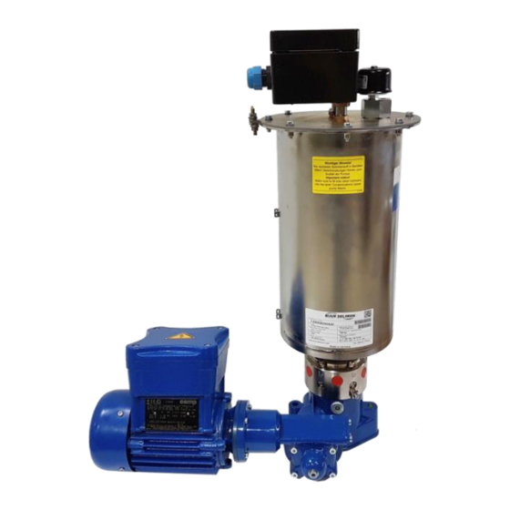
Pump FZ-A
according to
Atex
Page
BA_2005_2_GB_FAX
Advertisement
Table of Contents

Related Manuals for Bijur Delimon FZ-A


Summary of Contents for Bijur Delimon FZ-A
-
Page 1: Table Of Contents
Operating instructions Pump FZ-A according to Atex INDEX Page 1. General ................. 2 2. Safety ................2 – 4 A. Pump type ................5 B. Number of outlets ..............5 C. Revision ................5 D. Kinds of drive zone 2 and 22 ........6 – 8 E. -
Page 2: General
General Before installing and operating this equipment, we highly recommend that you become thoroughly familiar with these instructions. DELIMON does not accept liability, expressed or implied, for any direct or inconsequential injuries to personnel or damage to equipment, including process interruption, arising from the misuse or misapplication of its products. - Page 3 Safety ( continuation) Personnel qualification and training Personnel performing work required to install, operate, maintain or inspect this equipment must be adequately trained and qualified. In this regard, determination of competency, understanding and supervision levels required for individual assignment is left to the purchaser of the equipment. However, should assistance with on-site training be desired, please contact your local Bijur-Delimon office for assistance.
- Page 4 (continuation) Safety Additional Cautions for Pump Type FZ-A • Potential ‘pinch-point’ whenever closing the reservoir lid! When filling the reservoir while pump is operational, DO NOT put your hand into the reservoir. Risk of personal injury may result from contact with scraper blade and agitator.
-
Page 5: Pump Type
PRODUCT CHARACTERISTICS • possible versions: Guideline 94/9/EG – Atex category 2G and 3GD – for zone 1/2 and 22 • Central piston technique • Insert for anticlockwise and clockwise rotation • Feed volume per outlet up to 60cm • Lubricants: oil, grease, liquid grease •... - Page 6 KINDS OF DRIVE ZONE 2 AND 22 Shaft end free, gear ratio, 3 : 1 Shaft end free, gear ratio, 12 : 1 Shaft end free, gear ratio, 25 : 1 Shaft end free, gear ratio, 50 : 1 Step-down gear, gear ratio 95 : 1 Step-down gear, gear ratio 215 : 1 Step-down gear, gear ratio 345 : 1 Kinds of drive zone 2...
- Page 7 (continuation) KINDS OF DRIVE ZONE 2 AND 22 Drive with free shaft end The drive assembly consists of a ball bearing supported drive shaft and worm gear. A filler plug is provided to facilitate filling of the housing with oil. The filler plug must be removed prior to removal of the shaft with a mandrel.
-
Page 8: Kinds Of Drive Zone 2 And 22
(continuation) KINDS OF DRIVE ZONE 2 AND 22 Drive with reduction gear and motor POSITION OF DRIVE Position 1 left Position 5 right without RESERVOIR The reservoir lid is hinged for ease of access. It can be secured with a padlock to prevent unauthorized access or tampering. -
Page 9: Accessories
ACCESSORIES without Level switch Filling valve Level switch and filling valve Pressure control Level switch with connection box A lubricant level switch is available for reservoir monitoring. When the minimum or maximum level is reached, an electrical signal is generated by capacitive means. The signal may be used for the purpose of providing visual indication of status, or to activate an automated filling device. -
Page 10: Application
Application The pumps FZ-A are central piston-type pumps for the centralized lubricant supply to machines which are driven by an electric motor. (Fig. 1 and 2) Principle of operation The top of the worm wheel (1) driven by a worm shaft is provided with 2 drivers with recesses in which a crosspiece (2) engages. -
Page 11: Specification
Specifications Permissible back pressure: ....................... 200 bar for a short time: ......................250 bar Reservoir capacity : ....................... 8, 15 and 30 ltr. Permissible pump piston speed: with running drive: ........................max. 10 r.p.m. In case that higher speed or less then < 1 is requested and also when distributors ZPA or E 4 are installed downstream, ask manufacturer. - Page 12 After having refilled the grease, reattach the cotter pin in a professional way to secure the lid. Figure 3 Pump body FZ-A In case that the outlet bores are closed by item no. 2.17, item nos. 2.18 and 2.19 are to be removed from the pertaining relieving bores.
-
Page 13: Maintenance
Maintenance Definition of terms according to IEC 60079: Maintenance and repair: A combination of all activities being effected in order to maintain an object in a condition or to bring it back into this condition, so that the object in question comes up to the requirements of the specification concerned and ensures the execution of the functions required. - Page 14 (continuation) Maintenance Filling the grease tank As soon as approximately 3/4 of the tank capacity are consumed, the grease tank should be refilled. The grease level should never drop to a level where the feed screw is visible, because air may otherwise penetrate into the piping.
-
Page 15: Plates
Plates Name plate Type plate 110 x 60 mm (75312-4121) Zone 1 Zone 2 and 22 Page 15 of 15 BA_2005_2_GB_FAX...
Need help?
Do you have a question about the FZ-A and is the answer not in the manual?
Questions and answers