
Related Manuals for Gigaset N870E IP PRO


Summary of Contents for Gigaset N870E IP PRO
- Page 1 N870 / N870E IP PRO Multicell System Installation, configuration and operation...
-
Page 2: Table Of Contents
N870E IP PRO – base station with external antennas ....... . - Page 3 Content Telephony settings ..............83 General VoIP settings .
- Page 4 Content Appendix ................138 Safety precautions .
-
Page 5: Gigaset Dect Ip Pro Devices - Overview
Gigaset DECT IP PRO devices – overview Gigaset DECT IP PRO devices – overview Gigaset PRO DECT IP devices combine the possibilities of IP telephony with the use of DECT phones. They offer scalable telephone solutions for different company sizes and requirements. -
Page 6: N870 Ip Pro Multicell System - Introduction
N870 IP PRO is a DECT multicell system for connecting DECT base stations to a VoIP PBX. Units of the multi-cell system are available in two variants: N870 IP PRO with internal ¢ antennas and N870E IP PRO with external antennas ( p. 15). Components... - Page 7 Configuring handsets p. 74 Detailed information about approved Gigaset handsets can be found in the relevant user guide. These are provided on the Internet at wiki.gigasetpro.com. Phone system Connect your DECT phone system to a VoIP phone system, e.g.: •...
- Page 8 N870 IP PRO Multicell System – Introduction The DECT network The DECT network comprises the overall radio area of the multicell system in which the users can make and receive calls using their handsets. A specific DECT manager manages the whole or a part of the DECT network, one DM zone. It can comprise one or more clusters.
-
Page 9: N870 Ip Pro Installations
IP phones PABX web interface DECT manager DECT base stations N870 IP PRO Handover & roaming Gigaset handsets Small installations • Integrator, DECT manager and a base station are together at ..the same device. - Page 10 Up to 250 handsets can be registered....Large installations Configuration DECT base stations Gigaset from web N870 IP PRO handsets interface Handover & roaming DECT integrator...
- Page 11 N870 IP PRO Multicell System – Introduction Virtual integrator Virtualised INT • The integrator is available on a virtual machine. • Up to 100 DECT managers can be used. • Per DECT manager up to 60 base stations can be .
-
Page 12: Planning Your Dect Wireless Network
We also offer the N720 IP PRO Site Planning Kit to help you measure the wireless coverage and signal quality on your DECT network. Information about setting up and using the Gigaset meas- uring equipment can also be found in the "N870 IP PRO -Site Planning and Measurement Guide". -
Page 13: N870 Ip Pro - Overview
N870 IP PRO Multicell System – Introduction N870 IP PRO – overview Front Device button Set the device role; reset the device ¢ p. 21 LED displays Operation status of the device ¢ p. 24 LAN and power cable slot ¢... - Page 14 N870 IP PRO Multicell System – Introduction N870E IP PRO The Gigaset N870 IP PRO is also available as a variant with external antennas. Antennas ¢ Mounting the antennas p. 15...
-
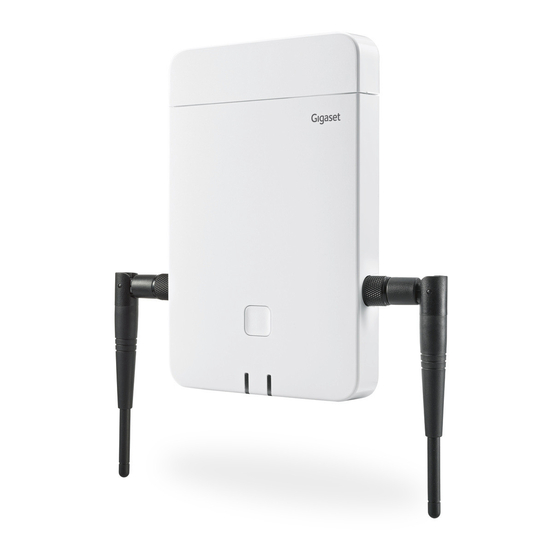
Page 15: N870E Ip Pro - Base Station With External Antennas
N870E IP PRO – base station with external antennas In contrast to the standard unit N870 IP PRO with two built-in internal wire antennas, N870E IP PRO offers the possibility to connect external antennas. For this purpose, the unit has two TNC connections. - Page 16 • to increase the DECT range: mounting external antennas in a better position than would be possible with an N870E IP PRO base due to spatial conditions, (e.g. distance to LAN connec- tion). Gigaset has selected and tested a number of third-party antennas. You can find recommendations at wiki.gigasetpro.com.
- Page 17 Make sure you tighten the screws on both sides Using N870E IP PRO together with N870 / N870E IP PRO N870E IP PRO is based on the same hardware and software and has the same feature set as N870 IP PRO, except for the external antenna equipment.
-
Page 18: First Steps
First steps First steps Package content • One N870 IP PRO or N870E IP PRO A device can play different device roles in ¢ the N870 IP PRO Multicell System ( p. 9) • Security leaflet • Screws and wall plugs for wall mounting Only for N870E IP PRO: •... -
Page 19: Mounting The Device
( p. 122). Whenever there are new or improved functions for your Gigaset device, firmware updates are made available for you to download to your DECT managers and your base stations. If this results in operational changes when using your phone, a new... - Page 20 First steps • The N870 IP PRO is designed for use in dry rooms with a temperature range of +5°C to +45°C. • Never expose the N870 IP PRO to heat sources, direct sunlight or other electrical appliances. • Protect your device from moisture, dust, corrosive liquids and fumes. Connecting to the LAN DECT manager and base stations must be connected to the same Ethernet or virtual LAN sharing a common broadcast domain.
-
Page 21: Installing The Integrator (Large Installation)
First steps Data protection notice Once the device is connected to the Internet, it automatically contacts the Gigaset support server to make it easier for you to configure the devices and to enable communication with Internet services. For this purpose, the system sends the following information when it is started and then every five hours: •... - Page 22 First steps You can use the device button on the front side to change the role of the device. The following settings are possible: • Base station • All in one (integrator/DECT manager/base station) with dynamic IP settings • All in one (integrator/DECT manager/base station) with fixed IP settings •...
-
Page 23: Wall Mounting
First steps Wall mounting N870 IP PRO is intended for wall mounting. After connecting the LAN cable and setting the device role you can place it to the destined location. max. ø 8 mm max. 3 mm max. ø 4 mm Fix the device to the wall with two screws: ¤... -
Page 24: Operation Hints
Operation hints Operation hints Light emitting diodes (LED) Depending on the device role the LEDs on the front side show different operational states. The LEDs can have three different colours (red, blue, green) or can be off. ¢ LED status display for base stations can be disabled ( p. -
Page 25: Resetting Base Stations To Factory Settings Via Power Procedure
Operation hints DECT manager (with DECT) LED 1 (left) LED 2 (right) Description 0.5 s 0.5 s 0.5 s 0.5 s 0.5 s 0.5 s 0.5 s 0.5 s Not synchronised, DECT ready Synchronised, DECT ready Synchronised, system traffic, no DECT traffic Synchronised, DECT or RTP traffic Synchronised, DECT or RTP overload Depending on traffic state... -
Page 26: Emergency Reset To Factory Settings
Operation hints Emergency reset to factory settings When the device is booting ¤ Press the device button for at least 10 seconds until all LED switch off release the button . . . the device is now in programming mode. ¤... -
Page 27: Configuring The System
Configuring the system Configuring the system System settings are made via the web configurator of the N870 IP PRO and cannot be changed using the handsets. This applies in particular for: • Registering and de-registering the handset at the telephone system, handset name. •... - Page 28 Configuring the system ¤ Enter gigaset-config.com in the address field of the web browser If several Gigaset devices can be reached at this address, a list is displayed Select device ¤ Enter the current IP address of the Integrator/DECT manager in the address field of the web browser (for example: http://192.168.2.10).
- Page 29 Configuring the system If you do not make any entries for a lengthy period (approx. 10 minutes), you are auto- matically logged off. The next time you try to make an entry or open a web page, the login screen is displayed again. Enter the password again to log back in. Any entries that you did not save on the telephone system before automatic logoff will be lost.
- Page 30 Configuring the system Help function Parameter description ¤ Click on the question mark next to the parameter for which you need information. A popup window is opened displaying a short description for the selected parameter. Function description for the entire web configurator page ¤...
- Page 31 Configuring the system Displaying/ hiding columns: ¤ Click on the View option menu on the right Select the columns you want to be displayed in the table ( = displayed/hidden). Names of columns which cannot be hidden are greyed out. Changing the number of list entries ¤...
-
Page 32: Web Configurator Menu Overview
Configuring the system Web configurator menu overview Menu options that are available also in the DECT managers user interface are highlighted grey. The other options are available only on the Integrator. Settings Network IP/LAN p. 33 DECT Manager Administration p. 36 Synchronisation p. -
Page 33: Network Administration
Network administration Network administration IP and VLAN settings This page is used to integrate the DECT multicell system into your company‘s local network. It is available in the Integrator and DECT manager user interface for the user role admin. ¤ Settings Network IP/LAN... - Page 34 Network administration Subnet mask The Subnet mask specifies how many parts of an IP address the network prefix must comprise. For example, 255.255.255.0 means that the first three parts of an IP address must be the same for all devices in the network, while the last part is specific to each device. In subnet mask 255.255.0.0, only the first two parts are reserved for the network prefix.
- Page 35 Network administration Ensure that the details in VLAN identifier or VLAN priority are set correctly. Incor- rect settings can cause problems when connecting the device for configuration purposes. Internal connections between DECT manager and base stations are not tagged and therefore phone functions are not affected. If required, you must carry out a hardware reset via device button ( p.
-
Page 36: Dect Manager Configuration
DECT manager configuration DECT manager configuration DECT manager configuration is only necessary in large installations with more than one DECT manager. It is only available on the Integrator user interface. To configure the DECT managers of your multicell system • Create a list of DECT managers with identifier on the administration page •... - Page 37 DECT manager configuration Capacity The value indicates how many base stations, handsets and calls can be handled by the DECT manager. It depends on the activation of the local base of this DECT manager ( p. 9). Medium The local base of this DECT manager is deactivated. The capacity is 60 external base stations, 250 handsets, 60 calls.
- Page 38 DECT manager configuration Deleting a DECT manager from the list ¤ Select the check box next to the DECT manager you want to delete. Multiple choice is possible. Click on Delete Confirm with Yes . . . all selected DECT managers are deleted. Before you delete a DECT manager, first consider what to do with the base stations assigned to it.
- Page 39 DECT manager configuration Example: RPN groups of neighbouring DECT managers To ensure, that a handset in 3 cannot see two identical RPN from the left 2 and the right 2 area, it is necessary, that any DECT manager coverage area in any direction is large enough, to provide enough isolation between two DECT manager areas of the same RPN group.
- Page 40 DECT manager configuration Server port ¤ Enter the port number, where the Syslog server expects to receive requests. Range: 1-65535; Default: 514 Transport protocol ¤ Select the transport protocol used for communication with the Syslog server. If you want to use the Integrator‘s system log server configuration settings for the DECT manager: ¤...
- Page 41 DECT manager configuration Blocking calls You can define a period of time in which all calls are blocked by the DECT manager, e.g. for main- tenance activities. If a user initiates a call in this time, a message is shown on the handset. Service action ¤...
-
Page 42: Dect Manager Registration
DECT manager configuration DECT manager registration You can now register the DECT managers at the Integrator. ¤ Assign the device role Base station and DECT manager with dynamic IP settings to the devices that are defined to act as DECT manager ( p. -
Page 43: Dect Manager Synchronisation
DECT manager configuration DECT manager synchronisation This page allows you to configure external synchronisation references for synchronisation clus- ters of your DECT managers. It is only available in the Integrator user interface for the user role admin. This way you could configure inter DECT manager synchronisation rules, to get base stations of multiple DECT managers in sync. - Page 44 DECT manager configuration Reference Reference to the synchronizing external DECT system. In case of Best DECT base of DM and LAN Master of DM the DECT manager identifier. In case of Ext RFPI xxx the RFPI or a part of an RFPI. Actions Adding a synchronization reference to the list ¤...
- Page 45 DECT manager configuration Ext RFPI xxx Level 1 base of the cluster will synchronise with another DECT system. Different RFPI matching levels are possible. Ext RFPI (full match) All bits of the RFPI are considered, i.e., one specific DECT system is referenced Ext RFPI (-1 match) -1 match: the last bit of the RFPI is ignored.
-
Page 46: Base Stations
Base stations Base stations The Integrator automatically recognises the base stations within the network. Base stations need to be confirmed, activated and synchronised. Base stations administration The page allows you to assign base stations to the DECT managers. It is only available in the Integrator user interface for the user role admin. Use the following web configurator page to assign base stations to the DECT managers. - Page 47 Base stations Status Synchronization status of the base station: Offline Not available Deactivated Available but not activated No sync Activated but not synchronised Sync Activated and synchronised, Sync overload Synchronised, but DECT overload; attempts were made at this base station to initiate more than the permitted simultaneous calls.
- Page 48 Base stations The export contains all data. The import does not contain the data of the local base station, because the local base station is physically bound to the (potential) new DECT manager. Please review your sync settings after a base station import. Enabling/Disabling LED status display at the base station LED displays are enabled by default on all base stations.
- Page 49 Base stations Status Synchronization status of the base station: Offline Not available Deactivated Available, but not activated No sync Activated, but not synchronised Sync Activated and synchronised Sync overload Synchronised, but DECT overload; attempts were made at this base station to initiate more than the permitted simultaneous calls.
-
Page 50: Base Station Synchronisation
Base stations Reduce transmitting power for external antenna operation The transmitting power of the external antennas can be reduced. This may be necessary in order not to violate country-specific emission regulations if the unit is equipped with external antennas and an external patch antenna (with a gain of 8dB) is used instead of the normal external sleeve antenna (with a gain of 3dB) ( p. - Page 51 Base stations Synchronisation always refers to a cluster. In case you set up several clusters that are not synchronised with one another, there will be no possibility of a handover or (over)load balancing between them. Synchronisation for handover between base stations in clusters managed by different DECT managers can be configured via DECT manager administration p.
- Page 52 Base stations a strictly limited number of hops along any branch in the synchronisation tree and to prevent circles between automatically optimised synchronisation chains. During configuration, assign one level in the synchronisation hierarchy (sync level) to each base station. Sync level 1 is the highest level; this is the level of the sync master and appears only once in each cluster.
- Page 53 Base stations Multicast destination address and ports: PTPv2: 224.0.1.129 UDP via ports 319/320 Proprietary DLS protocol: 239.0.0.37 UDP via ports 21045/21046 Cascaded switches might need uplink switching of these multicast packets to allow inter- switch LAN synchronisation. Otherwise you need isolated LAN-sync clusters, inter-cluster- synchronized via DECT.
- Page 54 Base stations deviations > 500 ns are accepted and might just generate first warnings. If the PTP sync packet deviation does continuously exceed this limit of 500 ns, the PTP synchronisation is considered broken and will lead to new start synchronisation procedure. •...
- Page 55 Base stations Example scenarios for small/medium systems (single DECT manager clusters) Synchronisation for handovers between base stations in clusters managed by one DECT manager are configured via the base station administration using the web configurator. Below are some example scenarios. Scenario 1: Pure DECT •...
- Page 56 Base stations Configuration: Base station Cluster Sync Level LAN Master Sync Slave DECT DECT DECT DECT DECT DECT DECT...
- Page 57 Base stations Scenario 2: Pure LAN • Use such a configuration, if all requirements for LAN synchronisation are fulfilled • Cluster 1-c is created to insure handover, roaming and load balancing • Base 4 is configured as LAN master • DECT level has no relevance for pure LAN synchronisation •...
- Page 58 Base stations Scenario 3: DECT-LAN mixed • Use such a configuration, if your environment is mainly able to synchronise via DECT but there are particular circumstances which cannot always guarantee reliable DECT synchroni- sation, e.g., a passage through a fire door •...
- Page 59 Base stations Configuration: Base station Cluster Sync Level LAN Master Sync Slave DECT DECT DECT DECT DECT DECT...
- Page 60 Base stations Example scenarios for large systems (multiple DECT manager clusters) Synchronisation for handovers between base stations in clusters managed by different DECT managers are configured via the DECT manager administration using the web configurator. Below are some examples based on two DECT managers. Detailed information on configuration can be found in the N870 IP PRO - Installation, configuration and operation.
- Page 61 Base stations Configuration: Base station DM Name Cluster Sync Level LAN Master Sync Slave DECT_Left_A DM_Left DECT_Left_B DM_Left DECT DECT_Right_A DM_Right DECT_Right_B DM_Right DECT...
- Page 62 Base stations Scenario 2: DECT – DECT – LAN • Integrator (virtual or embedded) • Two devices with role of DECT manager only • Every DECT manager has two DECT base stations • Cluster 1-c on the left side uses DECT synchronisation •...
- Page 63 Base stations Configuration: Base station DM Name Cluster Sync Level LAN Master Sync Slave DECT_Left_A DM_Left DECT_Left_B DM_Left DECT DECT_Right_A DM_Right DECT_Right_B DM_Right DECT...
- Page 64 Base stations Scenario 3: LAN – LAN with isolated PTP domain – DECT • Integrator (virtual or embedded) • Two devices with role of DECT manager only • Every DECT manager has two DECT base stations • Cluster 1-c on the left side uses LAN synchronisation •...
- Page 65 Base stations Further examples are available from wiki.gigasetpro.com. List of synchronised base stations All activated base stations contained in the Connected base stations list appear in the Base station synchronisation list. It is only available in the Integrator user interface for the user role admin. ¤...
- Page 66 Base stations DECT slave running external RFPI synchronisation rule: RFPI in Reference column Cluster configuration The page allows you to synchronise the system manually. ¤ Select the DECT manager you want to synchronise from the DM Name option menu . . . the cluster configuration of the selected DECT manager is displayed below Synchronising all clusters of the DECT manager ¤...
-
Page 67: Provider And Pbx Profiles
Provider and PBX profiles Provider and PBX profiles You can use up to 20 different VoIP PBX or VoIP provider profiles, e.g. • your company's VoIP PBX • and/or public providers from which you have requested VoIP services. This page allows you to create a list of systems providing VoIP connections and other services for your phones. - Page 68 Provider and PBX profiles Examples: sip.domain.net for john.smith@sip.domain.net 10.100.0.45 02871913000@10.100.0.45 Proxy server address The SIP proxy is your VoIP provider's gateway server and the first SIP server, where the device should send SIP requests and expects to receive requests. ¤ Enter the IP address or the (fully qualified) DNS name of your SIP proxy server (max.
- Page 69 Provider and PBX profiles ¤ Select which calls should be accepted: Secure Real Time Protocol Security is activated for voice connections. Accept non-SRTP calls Insecure calls are accepted even when SRTP is activated. Deregister detached HS The SIP account of handsets that are not reachable can be de-registered automatically. ¤...
- Page 70 Provider and PBX profiles The DHCP option 120 ”sip server” sent by a SIP phone would internally overrule the outbound proxy address and port setting. Outbound proxy mode is still and exclu- sively in the hands of the local device administrator. By setting Outbound proxy mode to Never, you can prevent any usage of DHCP option 120 by the DECT VoIP phone.
- Page 71 Provider and PBX profiles • send via RFC2833, if the PT (Payload Type) for the telephone event is provided by the peer • send via SIP INFO application/dtmf-relay, if SIP INFO method is supported by the peer • send in-band audio ¤...
- Page 72 Provider and PBX profiles PCMA/ (Pulse Code Modulation) Excellent voice quality (comparable with ISDN). The required PCMU bandwidth is 64 kbit/s per voice connection. PCMA (G.711 a law): Used in Europe and most countries outside of USA. PCMU (G.711 μ law): Used in USA. G.729A Average voice quality.
- Page 73 Provider and PBX profiles FROM Only the FROM information can be added. Caller identity in the form number@server, e.g.:12345678@192.168.15.1 PPI+FROM P-Preferred-Identity (PPI) or FROM can be added The P-Preferred-Identity header field is used from a user agent to a trusted proxy to carry the identity the user sending the SIP message wishes to be used for the P-Asserted-Header field value that the trusted element will insert.
-
Page 74: Mobile Devices
Mobile devices Mobile devices You can use the web configurator to register all handsets at the DECT network and for a VoIP connection. Use the add function of the Administration page to register single handsets or use the Registration Centre to register groups of handsets in one process. You can edit the settings for handsets, deactivate or delete them and make further settings e.g., for using directories and network services. - Page 75 Mobile devices Indicates, if DND (Do not Disturb) is activated for the handset. Type Model designation of the handset. Current firmware version of the handset. Authentication code defined for handset registration. Actions Adding a handset to the list ¤ Click on Add . . . the mobile devices data page is opened ( p.
- Page 76 Mobile devices Registering/de-registering handsets The page allows you to register a handset with the DECT network or to prepare the registration of numerous handsets via the Registration Center. You can assign a VoIP account, enable online directories, and make further settings for the handsets. It is available in the Integrator user interface for both the user role admin and user.
- Page 77 Mobile devices Registering a set of handsets You can register a set of handsets without restarting the registration mode. Prepare registration for new mobile devices as follows: ¤ Enter the actual IPUI and maybe an individual PIN ¤ Use wildcards as IPUI (0_1, 0_2, 0_3 … ) and preferably the same PIN for all handsets. ¤...
- Page 78 Mobile devices De-registering handsets ¤ In the handset list click on next to the handset you want to de-register. The status is Registered. ¤ From the RegStatus option menu select To deregister. Click on Set . . . the handset is de- registered.
- Page 79 Mobile devices Display name The display name is used for presentation of the caller‘s name. In rare cases SIP networks check the display name for any local policy of the SIP network. Usually, the display name is optional. ¤ Enter any name that should be shown for the caller on the other participant‘s display. Value: max.
- Page 80 Mobile devices LDAP authorisation type ¤ Select how the user authentication should be performed: Global Credentials are set for all handsets during the LDAP directory set-up. User Individual credentials are used. ¤ Enter Username and Password in the appropriate text fields. The credentials for the user’s SIP account are used (Authentication name and Authentication password).
- Page 81 Mobile devices ¤ Select Yes/No next to the message type (missed calls, missed alarms, new message on the network mailbox), to activate/deactivate the MWI LED for the message type. If Yes is selected, the message key will flash, if a new message of the selected types is received.
-
Page 82: Handset Registration Centre
Mobile devices Handset Registration Centre The registration centre allows you to register groups of handsets in one registration process. All handsets which are listed in the mobile devices list and have the registration status To register or Registering can be registered together. It is available in the Integrator user interface for both the user role admin and user. -
Page 83: Telephony Settings
Telephony settings Telephony settings General VoIP settings This page allows you to make some general settings for the VoIP connections. It is only available in the Integrator user interface for the user role admin. ¤ Settings Telephony VoIP SIP port ¤... -
Page 84: Audio Quality
Telephony settings Security settings The phone system supports the establishment of secure voice connections over the internet via TLS certificates. Thereby, public and private keys are used to encrypt and decrypt the messages that are exchanged between SIP entities. The public key is contained within the certificate of an IP entity and is available for everyone. -
Page 85: Call Settings
Telephony settings Call settings On this page you can make advanced settings for VoIP connections. It is only available in the Integrator user interface for the user role admin. ¤ Settings Telephony Call settings Call transfer Participants can transfer a call to another participant as long as the PBX/provider supports this function. - Page 86 Telephony settings Area Codes If you use VoIP to make a call to the fixed line, you may also have to dial the area code for local calls (depending on the provider). You can set your telephone system so that the access code is automatically predialled when any VoIP call is made in the same local area, and also for national long-distance calls.
-
Page 87: Xsi Services
Telephony settings XSI services BroadSoft XSI (Xtended Service Interface) allows remote applications to integrate with Broad- Soft services to perform telephony-related actions and to be notified about telephony events. The phone system enables the use of XSI services to provide the user with XSI directories and call lists. -
Page 88: Online Directories
Online directories Online directories N870 IP PRO allows you to set up up to ten corporate directories in LDAP format, a public and a corporate directory in XML format, different XSI directories, as well as a central directory and make them available to the registered handsets. Use the handset settings ( p. - Page 89 Online directories Server address / Server port ¤ Enter the URL of the LDAP server and the port the LDAP server expects database requests (Default: 389) LDAP Search base (BaseDN) ¤ The LDAP database is hierarchical in design. With the LDAP Search base (BaseDN) param- eter, stipulate in which area the search should begin.
- Page 90 Online directories Examples: AND operation: (& (givenName=%) (mail=%)) Searches for entries in which the first name and mail address begin with the characters entered by the user. OR operation: (| (displayName=%) (sn=%)) Searches for entries in which the display name or surname begins with the characters entered by the user.
- Page 91 Online directories Display format In the Display format field you can stipulate how the search result is to be displayed on the handset. ¤ Enter combinations of different name and number attributes and special characters. You can select common formats from the attributes that are listed in the Configuration of directory items section of the page.
-
Page 92: Online Directories In Xml Format
Online directories Field of a directory entry Attribute name in the LDAP database Street street City I, postalAddress postalCode Country friendlyCountryName, c Additional attribute user-defined ¤ Mark the check box Additional attribute can be dialled, if an additional attribute is defined and it is a phone number. -
Page 93: Online Directories - Xsi
Online directories Server url If the directory is configured, the server URL is displayed. Activation status Indicates if a directory and what kind of directory is activated. The directory is activated. The directory is not activated. ¤ Select Public or Corporate Entering the data for an XML directory Directory name ¤... - Page 94 Online directories Server address If XSI services are enabled the address of the XSI server is shown here. Enable list mode ¤ Define what should be initially shown, when the user opens the phone book. Activated: A list of all entries of the phone book is shown. Not activated: An editor is opened first that allows the user to select a specific search area within the phone book and thereby to reduce the number of entries.
-
Page 95: Central Phone Book
Online directories Central phone book You can provide a central phone book for all users‘ handsets. The phone book can be provided via a server in the network or uploaded directly from a computer to the phone system. It is only available in the Integrator user interface for the user role admin. The phone book must be available in well-defined XML format. - Page 96 Online directories A search in the central telephone book returns all entries that contain the characters entered by the user somewhere in the first or last name. Alternatively, the following can be set via provisioning: Only those entries are returned that have the entered characters at the beginning. Detailed information about provisioning parameters can be found at wiki.gigasetpro.com.
-
Page 97: Online Services
Online services Online services XHTML Additional functions as Info services, PBX control, and customer specific RAP (XHTML) applica- tions can be made available to the user via the handset menu Info Centre . For this purpose four additional menu entries can be defined that will be inserted into the handset user interface. The additional functions must be available as well formatted XHTML pages. -
Page 98: Application-Server
Online services Alternatively, the following credentials can be used. Username ¤ Enter a user name for access to the menu. Password ¤ Enter a password for access to the menu. Application-Server The phone system supports the AML feature (Alarming - Messaging - Location). AML includes the following functions: Alarming: The user can start an alarm from the DECT handset. - Page 99 Online services Deleting an application server from the list ¤ Select the check box next to the application server you want to delete. Multiple choice is possible. Click on Delete Conform with Yes . . . all selected application server are deleted.
-
Page 100: System Settings
System settings System settings Web configurator access rights On this page you define the access rights for the web configurator user interface. It is available in the Integrator and DECT manager user interface for both the user role admin and user. - Page 101 System settings Activated if password is longer than 7 characters The CLI access is automatically enabled if you have entered a valid password that has more than seven characters and click on the Set button. = enabled; = disabled CLI password ¤...
-
Page 102: Licensing
System settings Licensing For large installation and enterprise solutions licenses are needed. The page is only available in the user interface of a virtual integrator or on devices with the role Integrator only and for the user role admin. ¤ Settings System Licencing... -
Page 103: Provisioning And Configuration
VoIP phones support these features. However, for technical reasons auto-provisioning is not possible for all configuration parameters of the phone. Detailed information on how to establish a provisioning server and create provi- sioning profiles for Gigaset phones: wiki.gigasetpro.com ¤ Settings... - Page 104 System settings Auto configuration file If you have received a configuration file from your provider, you download it to the phone system. ¤ Click Browse... and select the configuration file from your computer‘s file system click on Upload . . . the selected configuration file is loaded. Start auto configuration ¤...
-
Page 105: Security
System settings Security The page allows you to organise the certificates used for secure internet communication and to define the credentials for HTTP authentication. It is only available in the Integrator user interface for the user role admin. ¤ Settings System Security Certificates... -
Page 106: Date And Time
System settings Import local certificate You can make available further certificates to your phone system. The certificates must have been downloaded to your computer before. ¤ Click Browse... and select the local certificate file from your computer‘s file system click on Upload . -
Page 107: Firmware
System settings Act as Local Time Server You can determine the internal time server to act as local time server for your network. If you have a time server available, you should not activate this function. ¤ Click on Yes/No to determine the internal time server to act/not to act as local time server. Date and time are synchronised system-wide on all base stations and handsets. -
Page 108: Save And Restore
System settings ¤ Click Browse... and select the firmware file from your computer‘s file system. Starting the firmware update ¤ At a specific date: Deselect the check box Immediately Enter the exact start time in the format: YYYY-MM-DD HH:mm ¤ Immediately: Select the check box next to Immediately (default) . -
Page 109: Reboot And Reset
System settings The configuration file contains all system data including the DECT registration data of the hand- sets, but not the calls list on the handsets. Saving configuration data ¤ Click on Save settings Select the location where the configuration file should be stored using the system file selection dialogue. -
Page 110: Dect Settings
System settings Base only The device is used as base station. All in one - dynamic IP The roles Integrator + DECT manager + base station are active. The network config- uration is set to dynamic IP. All in one - static IP The roles Integrator + DECT manager + base station are active. - Page 111 System settings Changing one of these settings requires a restart of the system. Ongoing calls will be cancelled. ECO DECT ECO DECT is an environment-friendly technology which reduces the power consumption and enables a variable reduction of transmission power. DECT Radiation power ¤...
- Page 112 System settings DECT radio settings Due to different national regulations DECT units are required to use different frequency ranges to make them compatible with DECT systems in other areas. You can adapt the frequency range of the N870 IP PRO Multicell System to the requirements of your region. DECT Radio band ¤...
-
Page 113: Diagnostics And Troubleshooting
Diagnostics and troubleshooting Diagnostics and troubleshooting Status information The status page offers important information on the system operation and the involved devices. ¤ Status Overview The following information is provided. • Integrator status Device name * • Device role * •... -
Page 114: Base Station Events
Diagnostics and troubleshooting System backup Besides Last backup date and time of the last backup is shown. As long as no backup has been created, Never is displayed instead. Creating a new backup or restoring an existing backup file: ¤ Click on System Save and restore . - Page 115 Diagnostics and troubleshooting Properties MAC address MAC address of the base station Radio Fixed Part Number, identifying the radio-entity Sync RPN RPN of the other base station the base station is synchronising with Sync Level Synchronisation level Statistics Conn Number of established connections on DECT MAC layer. For example, through user actions: VoIP calls, accesses to an online phone book, Internet connections, etc.
- Page 116 Diagnostics and troubleshooting Exporting the information into a CSV file For further processing of the statistic data you can export the data into a file with CSV (Comma separated Value) format. ¤ Click on Export Select the location where the file should be stored using the system file selection dialogue.
-
Page 117: Incidents
Diagnostics and troubleshooting Resetting the statistics ¤ Click on Reset all . . . the counters in the table are reset to 0. Filtering the list ¤ From the Choose column option menu select the column for which you want to set a filter. Note that columns may be hidden. -
Page 118: System Log And Snmp Manager
Diagnostics and troubleshooting Actions Downloading detailed information to a file To get detailed information about the circumstances causing the error, you can download the incident information to a file. If required, you can pass it to the responsible service personnel. ¤... - Page 119 Diagnostics and troubleshooting To set up the system log server individually for each DECT manager p. 39. SNMP statistics The Simple Network Management Protocol (SNMP) is a common protocol used for monitoring and controlling of network devices. To gather management and statistic information concerning base station events to be processed by an SNMP manager you have to enter the address and authentication information according to the SNMP server configuration.
- Page 120 Diagnostics and troubleshooting SNMP commands (examples): Obtaining MIB information starting from a specific MIB variable: snmpwalk -v3 -l authPriv -u admin -a SHA -A snmp-admin -x AES -X snmp-admin “ipaddress” 1.3.6.1.4.1.32775.1.1.1 Obtaining next information in the MIB tree: snmpgetnext -v3 -l authPriv -u admin -a SHA -A snmp-admin -x AES -X snmp-admin “ipaddress” 1.3.6.1.4.1.32775.1.1.1.1 Configuring SNMP-Traps: trapsess -v 3 -u admin -l AuthPriv -a SHA -A snmp-admin -x AES -X snmp-admin "ipaddress"...
-
Page 121: Diagnostics
Diagnostics and troubleshooting Diagnostics For diagnostic purposes you can create a dump with different contents. A dump may help soft- ware developers and system administrators to diagnose, identify and resolve problems that led to system failures. ¤ Settings System Diagnostics A standard set of diagnostic info will be downloaded. -
Page 122: Migration
Migration Migration In order to migrate a small or medium N870 IP PRO Multicell System with one single DECT manager into a multi DECT manager installation, please perform the following steps: ¢ 1 Install the required licenses ( p. 102) 2 Export the base station and handset configuration of your current installation ¤... -
Page 123: Using A Handset Connected To An N870 Ip Pro Base
Information about this will be found in the relevant handset user guide. The availability of functions or their designations may differ on individual handsets. For information about which Gigaset handsets support the complete functionality of the N870 IP PRO muliticell system please refer to wiki.gigasetpro.com. Making calls You can make calls using any handset registered to your N870 IP PRO. -
Page 124: Accepting Calls
Using a handset connected to an N870 IP PRO base Dialling from the redial list The redial list contains the numbers last dialled with the handset. ¤ Briefly press the Talk key . . . the redial list is opened select an entry press the Talk key... -
Page 125: Conversation With Three Participants
Using a handset connected to an N870 IP PRO base Using a PBX call manager In case a PBX call manager is used it is possible to define that incoming calls are accepted directly via headset or handsfree. This has to be configured for the handset via web configurator in the ¢... -
Page 126: Message Indication
Using a handset connected to an N870 IP PRO base Ending a currently active call ¤ Options End Active Call the connection to the other caller is reactivated . . . ¤ Press the End call key . . . a recall to the first participant is initiated Conference Speaking to both participants at the same time. -
Page 127: Using Directories
Using a handset connected to an N870 IP PRO base Message Waiting Indication (MWI) For each message type (missed call, missed alarm, new message the network mailbox) the MWI option can be activated or deactivated via the web configurator. If activated, the LED on the message key flashes, in the case a new message arrives indi- cating missed calls, missed alarms or new messages on the network mailbox. -
Page 128: Using The Network Mailbox
Using a handset connected to an N870 IP PRO base Using the network mailbox The network mailbox accepts incoming calls made via the corresponding line (corresponding VoIP phone number). Prerequisites In order to allow the user to listen voice messages stored one a network mailbox the following settings are necessary: On the VoIP PBX ¤... -
Page 129: Ldap Directory - Configuration Example
LDAP directory – configuration example LDAP directory – configuration example To allow the entries of an LDAP directory to be displayed on the handsets, you will need to configure the phone’s LDAP client. This involves the following: • Setting up access to the LDAP server and database ¢... - Page 130 LDAP directory – configuration example It is also possible to use individual access data for each handset ( p. 78). LDAP Search base (BaseDN) The LDAP Search base (BaseDN) parameter specifies the starting point for the search in the LDAP directory tree. This starting point must be defined on the LDAP server and entered here for the LDAP client according to the server configuration.
-
Page 131: Filters
LDAP directory – configuration example Filters With filters you define criteria by which the phone searches for certain objects in the LDAP data- base • The name filter determines which attributes are used in the search for directory entries. • The number filter specifies which attributes are used for the automatic search in the LDAP database when phone numbers are entered. - Page 132 LDAP directory – configuration example Operator Meaning Example Equality (attribute1=abc) Negation (!(attribute1=abc)) >= Greater than (attribute1>=1000) <= Less than (attribute1<=1000) Proximity (LDAP server dependent) (attribute1~=abc) Wildcard (attr1=ab*) or (attr1=*c) or (attr1=*b*) Multiple criteria can be connected with logical AND (&) and/or OR operators (|). The logical oper- ators "&"...
- Page 133 LDAP directory – configuration example Name filter The name filter determines which attributes are used for the search in the LDAP database. Examples: (displayName=%) The attribute displayName is used for the search. The percent sign (%) is replaced with the name or part of the name entered by the user.
-
Page 134: Attributes
LDAP directory – configuration example Attributes For a directory entry (an object), a series of attributes are defined in the LDAP database, e.g. surname, first name, phone number, address, company etc. The set of all attributes that can be stored for an entry is stored in the schema of the relevant LDAP server. To access attributes or define search filters, you must know the attributes and their names in the LDAP server. -
Page 135: Display On The Handsets
LDAP directory – configuration example The attributes First name and Surname will be used for the following functions: • Display in the list of directory entries in the form Surname, First name • Alphabetical sorting of the directory entries on the phone •... - Page 136 LDAP directory – configuration example The LDAP directory is displayed according to the following rules: Our Directory • The search begins in the directory/subdirectory which is defined as the search base on the LDAP server and specified Albert with the LDAP Search base (BaseDN) parameter in the web ¢...
- Page 137 LDAP directory – configuration example Dialling a number from the directory ¤ to select the entry you want in the directory. Brown, Charly ¤ Press the Talk key . If only one phone number is stored, it Phone (office): is dialled. If there are several phone numbers, they are 0987654321 displayed in a selection list.
-
Page 138: Appendix
(e.g. a pacemaker), please contact the device manufacturer. They will be able to advise you regarding the susceptibility of the device to external sources of high frequency energy (for the specifications of your Gigaset product see "Specifications" ¢ p. 141). -
Page 139: Authorisation
Appendix Our Gigaset pro reseller will be happy to help with any further questions related to your Gigaset N870 IP PRO. Authorisation Voice over IP telephony is possible via the LAN interface (IEEE 802.3). Depending on your telecommunication network interface, an additional router/switch could be necessary. -
Page 140: Care
Appendix Care Wipe the device with a damp cloth or an antistatic cloth. Do not use solvents or microfibre cloths. Never use a dry cloth; this can cause static. In rare cases, contact with chemical substances can cause changes to the device’s exterior. Due to the wide variety of chemical products available on the market, it was not possible to test all substances. -
Page 141: Technical Data
Technical data Technical data Specifications Power consumption Operation as N870 IP PRO (DECT manager) < 3.8 W Operation as N870 IP PRO (base station) < 3.8 W General specifications DECT Manager and base stations Power over Ethernet PoE IEEE 802.3af < 3.8 W (Class 1) LAN interface RJ45 Ethernet, 10/100 Mbps Protection class IP20... -
Page 142: Accessories
Equipment for planning and analysing your DECT multicell system. The case contains two cali- brated Gigaset S650 H PRO handsets and one Gigaset N510 IP PRO base station, plus other useful accessories for measuring the signal quality and wireless coverage on your DECT network. -
Page 143: Index
Index Index ....... 85 ......7, 11 Access code Base station . - Page 144 Index ......91, 134 cn, attribute DECT traffic ........71 .
- Page 145 IP configuration ..74 Gigaset N720 SPK PRO (Site Planning Kit) IPUI (International Portable User Identity) ......142 .
- Page 146 ......15 N870E IP PRO ....... . 89 LDAP filter .
- Page 147 Index ....134 Phone number in directory Ringback .......7 .
- Page 148 Index ....131 Synchronisation example User input, place holder ....60 large, DECT-DECT-DECT User name .
- Page 149 Issued by Gigaset Communications GmbH Frankenstr. 2a, D-46395 Bocholt © Gigaset Communications GmbH 2021 Subject to availability. All rights reserved. Rights of modification reserved. www.gigasetpro.com...
Need help?
Do you have a question about the N870E IP PRO and is the answer not in the manual?
Questions and answers