Advertisement
Quick Links
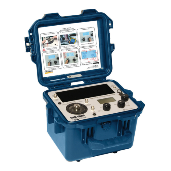
HI-903 HARDY SHAKER
Installation Manual
1180
1. OVERVIEW
The METRIX Model HI-903 Portable
Vibration Calibrator provides a field
tested method for on-the-spot dynamic
verification of accelerometers, velocity
pickups and non-contact displacement
transducers. Optional mounting fixtures
and hardware needed to connect
transducers to the HI-903 mounting
platform are available upon request.
A closed-loop control algorithm provides
enhanced stability and accuracy of
frequency and amplitude levels.
DOC# 100928 • REV A (October 2017)
The HI-903 incorporates a built-in
sine wave oscillator, power amplifier,
electrodynamic shaker, NIST traceable
reference accelerometer, digital display,
and internal memory. The HI-903 is
completely self-contained and operates
on battery or AC power.
The built-in reference accelerometer
is attached permanently to the shaker
armature, maximizing the accuracy
between the reference accelerometer
and the test transducer. The HI-903 is
designed to provide long-term reliable
performance over the frequency range of
7 Hz to 10 kHz. The HI-903 can be used
for a variety of applications that include:
•
Verification and calibration of
vibration transducers and related
vibration test systems
Verification of connector and cabling
•
integrity
Confirm machine vibration alarm trip
points are set properly and ensure
end-to-end functionality of vibration
monitoring systems.
Notes
•
Loads of up to 800 gram (28.3
oz) can be mounted directly to
the HI-903 mounting platform.
Larger loads may be applied to the
platform, however, if prolonged
testing of a heavy load is planned,
we recommend using an external
transducer suspension system.
Under these conditions the vibration
waveform should be viewed on the
oscilloscope to aid in positioning
the test transducer and platform to
reduce distortion that can occur with
very heavy weights.
Advertisement

Subscribe to Our Youtube Channel
Related Manuals for Metrix HI-903


Summary of Contents for Metrix HI-903
- Page 1 The HI-903 is designed to provide long-term reliable performance over the frequency range of 7 Hz to 10 kHz. The HI-903 can be used for a variety of applications that include: • Verification and calibration of...
- Page 2 • The HI-903 should always be operated on a stable, flat surface. The HI-903 is designed for field test applications but care must be taken to maintain the integrity of the mounting platform assembly • Hearing protection recommended when operating the HI-903 for an extended...
-
Page 3: Basic Operation
For the basic operation of the HI-903, a vibration sensor and appropriate cable are needed. Typically the HI-903 is used as a vibration excitation source and as a readout device with the vibration sensor connected to the HI-903’s Test Sensor BNC Input. - Page 4 Rotate the FILE dial and select “Save.” This will save all data points in • the listed record number. The record number shown on the screen increments automatically. Doc# -RevA Page 4 of 33 100928 • HI-903-Shaker • October 2017...
- Page 5 20 minutes of inactivity when not plugged in to the charger. After Testing 20. Suggested Best Practice: Plug the HI-903 into an AC power source when not in use. This will ensure the batteries are fully charged for your next test and also help to maximize the lifespan of the batteries.
- Page 6 Report Generation Workbook Calibration data can be saved into the HI-903’s internal memory and easily exported to a personal computer using a USB Flash Drive. The HI-903 Portable Vibration Calibrator includes a pre-formatted USB Flash Drive with a Microsoft Excel Report Generation Workbook for the creation of customizable calibration certificates.
- Page 7 • SLINCert - Displays the linearity response calibration certificate using static linearity data from LINData. • Route Creator – If firmware option HI-903 CALROUTE is ordered, this tab can be used to create semi-automated tests with instant pass/fail notification for almost any vibration sensor.
- Page 8 The “Amplitude Unit Screen” shows all 10 available amplitude scales on model HI-903 Portable Vibration Calibrator. Use the FREQUENCY dial to highlight each scale and press the dial to toggle the scale on or off. A filled circle next to the scale indicates it is active.
- Page 9 But the test can also be de-activated at any time, putting the HI-903 back into manual operation mode. When a Calibration Route is active the HI-903 can only adjust to the pre-defined amplitude and frequency points that have been programmed.
- Page 10 The HI-903 can only simulate vibration in CPM values that are multiples of 60. I.e. 1800 CPM, 3600 CPM, 4200 CPM, etc. If a value is entered that is not a multiple of 60, the HI-903 will adjust down to the nearest CPM value that is a multiple of 60.
- Page 11 If the sensor under test’s sensitivity is above 105 mV/g or below 95 mV/g the HI-903 will alert the user that test point failed. • The file name will be CaseAccel_Route.pvc, when uploading to the HI-903 one would choose this file. •...
- Page 12 & Activating a Calibration Test (Route) With the calibration test saved as a .pvc file to the Calibration_Route folder on the USB and the USB inserted into the port on the HI-903 the following instructions detail how to upload to model HI-903 and activate: 1.
- Page 13 The calibration test has been created and saved to the USB. It has also been uploaded and activated in the HI-903 using the previous section. The following instructions detail usage of the HI-903 while the pre-programmed test is active. To use the HI-903 in manual mode again the calibration route must be de-activated (see next section).
- Page 14 If no test is active pressing file while this option is highlighted does nothing. • Eject USB – allows user to safely remove the USB drive from HI-903 Definition of Frequency Units • Hertz (Hz) is defined as the number of periodic cycles per second and it is a standard unit for measuring signal frequency.
- Page 15 Input / Output EXTERNAL SOURCE IN Input BNC It is possible to drive the HI-903 by using an external signal source or a function generator. First, connect a signal source to the EXTERNAL SOURCE IN BNC Input located on the top left corner of the unit. To enable the EXTERNAL SOURCE IN input, press the FREQUENCY dial to enter the “Calibration Options”...
-
Page 16: Theory Of Operation
The diagnostic screen can be displayed by holding down the file button for approximately 2 seconds. This screen displays information about the operation of the HI-903. The information found in this menu is displayed in real time: Reference ICP Bias Voltage Test Sensor Bias Voltage Test Sensor Type: Voltage, ICP®... - Page 17 The reference accelerometer is a PCB Piezotronics ICP® quartz shear sensor, integrated into the mounting platform. A calibration “standard” maintained by METRIX is used to calibrate the HI-903 as a complete system and provides NIST traceability. Traceability information can be viewed under the tools menu as described in the previous section.
- Page 18 Battery and Charger The Model HI-903 can be operated from AC line power or from its internal rechargeable battery. When the external power supply is connected, it becomes the primary power source, operating the unit while simultaneously charging the battery.
- Page 19 Under mild operating conditions (lower mass transducers at lower test amplitudes), a fully charged battery will allow the HI-903 to operate for up to 18 hours. The charge life of the battery depends on both the length of use and the amount of power (dependent upon payload, frequency and amplitude) required for a particular test.
-
Page 20: Specifications And Performance
], [in/s], [mm/s], [mils] or [µm]. SUT Specifications SUT input Voltage range 10V AC pk-pk SUT ICP current SUT Bias offset measurement range 0-25 V DC SUT Bias Fault Voltage limits 2V/15V DC Doc# -RevA Page 20 of 33 100928 • HI-903-Shaker • October 2017... - Page 21 This is a safeguard against side loading the shaker. In some cases of extremely heavy shaker payloads at high vibration levels (depending on the frequency), the HI-903 may exhibit both frequency and amplitude instabilities. In this case, please reduce the excitation amplitude and/or the payload to eliminate the effect.
- Page 22 Doc# -RevA Page 22 of 33 100928 • HI-903-Shaker • October 2017...
-
Page 23: Recommended Practices
HI-903 should be evaluated further to determine the root cause of the discrepancy. Field repair of the HI-903 is not possible, so if performance of the HI-903 is out of specification, it should be sent back to Metrix for evaluation, repair and recalibration. - Page 24 Tip: magnetically mounting sensors greatly reduces high frequency response. A ferrous magnet target, mounting pad, is included with the HI-903. One can install this pad on the shaker and mount accelerometers magnetically. Always rock the sensor in place as one would on the machine.
- Page 25 (proximitor®) must be matched in order to obtain the expected output from this type of transducer. [Proximitor is a registered trademark of Bently Nevada.] Doc# -RevA Page 25 of 33 100928 • HI-903-Shaker • October 2017...
- Page 26 1. Remove the (2) 10-32 pan head screws on the user panel of the portable vibration calibrator (white arrows in picture below). 2. Install the AISI 4140 steel target into the shaker on the mounting platform. Doc# -RevA Page 26 of 33 100928 • HI-903-Shaker • October 2017...
- Page 27 100 mils before the micrometer runs out of travel. (for 200 mV/mil probe with 10- 90 mils range). Non-contact displacement sensors come in various lengths so Doc# -RevA Page 27 of 33 100928 • HI-903-Shaker • October 2017...
- Page 28 5. Finalize the assembly by attaching probe bar, microarm, non-contact displacement sensor, and micrometer on top of the spacers and secure with provided panel screws. Doc# -RevA Page 28 of 33 100928 • HI-903-Shaker • October 2017...
- Page 29 6. Create a linearity test report for auditing purposes. Connect the output of the probe driver to the TEST SENSOR INPUT BNC. Make sure model HI-903 is in “voltage mode” by pressing and holding the AMPLITUDE dial or using the TEST SETTINGS MENU.
- Page 30 USB drive. Each time tests are exported from HI-903 to USB they are saved within a folder representing the date and time they were exported. Once data is imported press View Certificate. Enter any desired notes or comments into the report, save and/or print.
- Page 31 6 quickly, complete three full rotations of the micrometer and then move 5 more mils. 7. All data is now entered, press View Certificate to view, edit, save and print the report Doc# -RevA Page 31 of 33 100928 • HI-903-Shaker • October 2017...
- Page 32 For safety or insurance audits it may be helpful to have test reports for 4-20 mA vibration transmitters. The HI-903 cannot read DC voltage or current, thus for this test a calibrated multi-meter (capable of measuring current) is required. A 24 VDC power supply must be used to power the sensor.
- Page 33 If the unit is removed from the case, the NIST calibration is void. Recertification can only performed after re-assembly. Doc# -RevA Page 33 of 33 100928 • HI-903-Shaker • October 2017...
Need help?
Do you have a question about the HI-903 and is the answer not in the manual?
Questions and answers