Table of Contents
Advertisement
O
X
5
0
O
X
5
0
O
X
5
0
O
X
5
0
O
X
5
0
O
X
5
0
Copyright ©
P
o
r
t
a
b
l
e
P
o
r
t
a
b
l
e
P
o
r
t
a
b
l
e
2
2
:
2
c
h
a
n
2
2
:
2
c
h
a
n
2
2
:
2
c
h
a
n
4
2
:
2
c
h
a
n
2
:
2
c
h
a
n
4
4
2
:
2
c
h
a
n
O
p
e
r
a
t
i
n
g
I
n
s
t
r
u
O
p
e
r
a
t
i
n
g
I
n
s
t
r
u
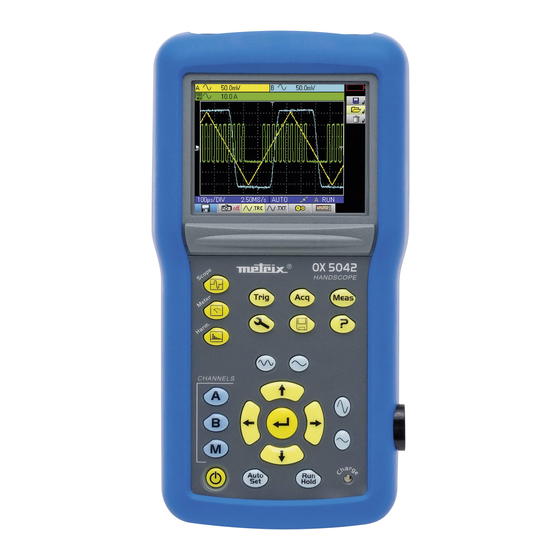
Operating Instructions
Chauvin Arnoux, Inc d.b.a. AEMC Instruments
15 Faraday Drive, Dover NH 03820 USA
Tel. (603) 749-6434 - Fax (603) 742-2346
O
s
c
i
l
l
o
s
c
O
s
c
i
l
l
o
s
c
O
s
c
i
l
l
o
s
c
n
e
l
s
,
2
0
M
n
e
l
s
,
2
0
M
n
e
l
s
,
2
0
M
n
e
l
s
,
4
0
M
n
e
l
s
,
4
0
M
n
e
l
s
,
4
0
M
c
t
i
o
n
s
c
t
i
o
n
s
99-MAN 100378 - v1 07/12
o
p
e
s
o
p
e
s
o
p
e
s
H
z
H
z
H
z
H
z
H
z
H
z
Advertisement
Table of Contents


Need help?
Do you have a question about the OX 5042 and is the answer not in the manual?
Questions and answers