
Related Manuals for Metrix OX 832


Summary of Contents for Metrix OX 832
- Page 1 OX 832 30 MHz-DIFFERENTIAL OSCILLOSCOPE User's manual Copyright © 906121641 - Ed. 3 - 04/00...
-
Page 2: Table Of Contents
CONTENTS 1. GENERAL INSTRUCTIONS....................... 3 1.1. Safety precautions........................ 3 1.1.1. Before use ........................3 1.1.2. During use ........................3 1.1.3. Symbols......................... 4 1.1.4. Instructions ........................4 1.2. Guarantee ..........................4 1.3. Maintenance and metrological verification................4 1.4. Servicing ..........................4 2. -
Page 3: General Instructions
GENERAL INSTRUCTIONS You have just purchased a 30 MHz-differential oscilloscope; we congratulate you on your choice of this high quality product. This apparatus complies with IEC safety standard 61010-1 +A1 +A2 (1995) single insulation, dealing with electronic measurement instruments. Please read these instructions carefully and respect the usage precautions, in order to obtain the best use from it. -
Page 4: Symbols
1.1.3. Symbols Refer to the user's manual. Incorrect use may result in damage to the device or its components. Ground Risk of electric shock 1.1.4. Instructions - Before opening the apparatus, always disconnect it from the mains power supply and measurement circuits, and make sure that you are not charged with static electricity which could damage internal components. -
Page 5: Instrument Description
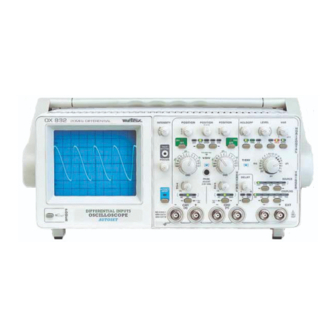
INSTRUMENT DESCRIPTION This instrument is a 30 MHz portable differential oscilloscope with AUTOSET. Its technology has been designed to satisfy the most demanding users. It is intended for electrotechnicians and electronics experts (operation in normal or differential mode). This oscilloscope's inputs can operate in both traditional and differential mode (independent switching accessible on the front): in traditional mode ∗... - Page 6 OX 832 30MHz 30 29 36 35 Figure 1 : Face avant 30 MHz-differential oscilloscope...
-
Page 7: Front Panel Description
2.1. Front panel description FOCUS focus adjustment • TRACE ROTATION adjustment of the horizontal trace alignment • adjustment of the trace brightness INTENSITY • selection of the vertical sensitivity for CH1 VOLT/DIV • switching to normal or differential operating mode of CH1 channel CH1 DIFF •... -
Page 8: Rear Panel Description
2.2. Rear panel description Figure 2 (40) Location of the optional HA1255 PROGRAMMING KIT connector This RS232C serial link (40) establishes the communication between the oscilloscope and a PC or compatible computer. It enables : - the remote programming of the oscilloscope - the reading of the oscilloscope configuration (41) Mains plug... -
Page 9: Getting Started
GETTING STARTED Respect the safety instructions indicated in Chapter 1. - Position the rotary controls as indicated in the figure 1. - Press the POWER key (39): the last memorised configuration of the front panel is restored. - Validate the AUTO key (19). - Adjust : - brightness with the INTENSITY potentiometer (3), - the thickness of thetraces with the FOCUS potentiometer (1),... - Page 10 Figure 3 30 MHz-differential oscilloscope...
-
Page 11: Vertical Channels
3.2. Vertical channels Refer to figure 3. (6) - (11) POSITION - Vertical centring of the CH1 (6) and CH2 (11) traces. POSITION - Horizontal centring of the traces. This command acts simultaneously on CH1 and CH2. (4) - (10) VOLT/DIV - CH1 (4) and CH2 (10) vertical sensitivity : 14 positions (10 mV to 200 V/div.). -
Page 12: Display Modes
3.3. Display modes Refer to figure 3. CH1 DIFF - Switch of channel CH1 to normal/differential mode. In normal mode - LED not lit - the display corresponds to the signal DIFF present on channel CH1+. In differential mode - LED lit - the display corresponds to the difference between the signals present on channel CH1+ and CH1-. -
Page 13: Timebase
3.4. Timebase (Refer to figure 4, next page). (20) T/DIV - Sweep coefficient selection : 18 positions (0.5 s to 200 ms/div.) (17) VAR - Continuous adjustment of the sweep coefficient of timebase When the knob is locked in the left-hand position, the UNCAL indicator is out. (13) HOLDOFF - Continuous adjustment of the minimum time between two successive sweeps. - Page 14 Figure 4 30 MHz-differential oscilloscope...
-
Page 15: Trigger Delay (Delay)
(26) - (25) EXT- EXT+ Input of the external synchronisation signal by the + and - BNC sockets. (Refer to §. 5. SPECIFICATIONS). (23) - (24) COUPLING - Coupling of the trigger source The filtering activated only acts on the trigger channel, not on the display. This COUPLING function is inactive in XY mode (indicators out). - Page 16 Figure 5 : Probe incorrectly compensated in low frequency Figure 6 : Low frequency compensation correct 30 MHz-differential oscilloscope...
-
Page 17: Applications
APPLICATIONS 4.1. Visualisation of the calibration signal - Connect the PROBE output (33) to CH1 input (34) by using a 1/1 or 1/10 measurement probe. - Select the following functions: • CH1 sensitivity (4) or CH2 (10): 0.1 V/div. (1/1); 10 mV/div. (1/10) •... -
Page 18: Specifications
SPECIFICATIONS Only the values affected by tolerances or limits constitute guaranteed values (after half an hour's warming up). Values without tolerances are given for information. 5.1. Vertical deflection CH1 - CH2 Specifications Comments Characteristics Bandwidth at - 3 dB > 20 MHz on ranges 10 mV to 50 mV/div. measured on 6 divisions >... -
Page 19: Horizontal Deflection
5.2. Horizontal deflection Characteristics Specifications Comments Sweep coefficients 0.5 s to 200 ms/div. Sequences 1-2-5 Accuracy on all ranges ± 3 % i. e. 18 positions Expansion x 10 Accuracy : ± 5 % used to obtain 20ns/div. Variable coefficient Division of the s/div. -
Page 20: Trigger Delay Coefficient
5.3.1. Trigger delay coefficient Scanning time range Delay range (approx.) 0.5 s/div. 0.5 s to 5 s 1 s/div. 1 s to 10 s 2 s/div. 2 s to 20 s 5 s/div. 5 s to 50 s 10 s/div. 10 s to 100 s 20 s/div. -
Page 21: General Characteristics
5.5. General characteristics Cathode ray ube Tube mono-accelerator cathode-ray tube Type rectangular with 13 cm diagonal internal graticule Graticule 8 vertical divisions with 5 subdivisions 10 horizontal divisions with 5 subdivisions 1 division = 1 cm Screen phosphor with average GY persistence Trace adjustment of trace rotation adjustment of focusing... -
Page 22: Supplies And Options
Mechanical characteristics Stackable instrument, the handle being used as a stand Weight: ≈ 7 kg Dimensions : When packed Dimensions : 550 x 460 x 280 mm Weight: ≈ 8.5 kg SUPPLIES AND OPTIONS 6.1. Accessories 6.1.1. Provided with the apparatus User’s manual 906121641 •...
Need help?
Do you have a question about the OX 832 and is the answer not in the manual?
Questions and answers