
Subscribe to Our Youtube Channel
Related Manuals for Metrix MX 435D


Summary of Contents for Metrix MX 435D
- Page 1 MX 435D CONTRÔLEUR D'INSTALLATIONS ÉLECTRIQUES DIGITAL EARTH TESTER Notice de fonctionnement page 1 Chapitre User's manual page 25 Chapter Copyright © X03264A00 - Ed. 05 - 04/16...
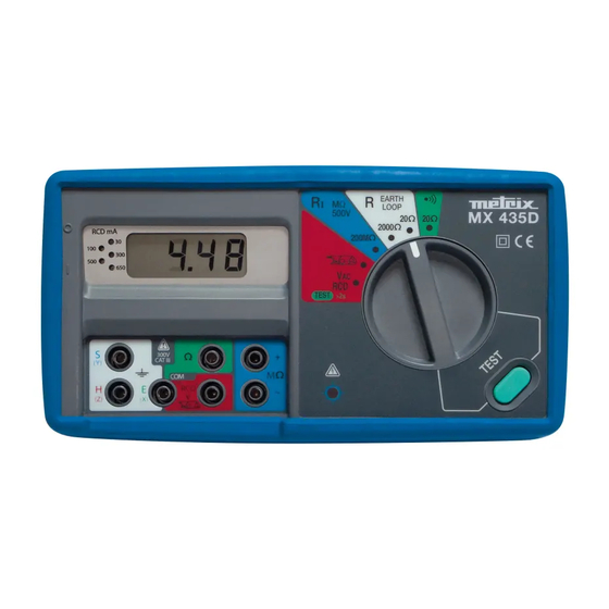
- Page 2 FACE AVANT / FRONT PANEL 12 11 FACE ARRIÈRE / REAR PANEL Contrôleur d'installations électriques...
- Page 3 LEGENDE Interrupteur Marche/Arrêt « O/I » Mesure de terre/loop 20 Afficheur LCD Mesure de terre/loop 2000 Bornes mesure de terre E, S, H Bornes tension/courant V / RCD Mesure de courant par pince (AAC) Mesure de tension VAC / Test RCD Bornes continuité...
-
Page 4: Table Of Contents
Chapitre I TABLE DES MATIERES INSTRUCTIONS GENERALES ......................... 1 1.1. Précautions et mesures de sécurité ....................1 1.1.1. Avant utilisation ........................... 1 1.1.2. Pendant l'utilisation ........................1 1.1.3. Symboles ............................ 2 1.1.4. Consignes ........................... 2 1.2. Garantie .............................. 3 1.3. Réparation et vérification métrologique .................... -
Page 5: Instructions Generales
Chapitre I INSTRUCTIONS GENERALES Vous venez d'acquérir un contrôleur d'installations électriques multifonctions ; nous vous remercions de votre confiance. Cet appareil est conforme à la norme de sécurité NF EN 61010-1 Ed. 2 (2001), relative aux instruments de mesures électroniques. Il permet de vérifier les installations conformes à la norme IEC 61557. -
Page 6: Symboles
Chapitre I sous tension. isolement, continuité, terre), des protections électriques se mettent en oeuvre (CTP). Il faudra attendre leur refroidissement ( 3 minutes) pour commencer de nouvelles mesures. de tout nouveau test p refroidissement interne suffisant avant de relancer une série de mesures. Si le symbole «... -
Page 7: Garantie
Chapitre I 1.2. Garantie Ce matériel est garanti contre tout défaut de matière ou vice de fabrication, conformé- -tion délivré par nos laboratoires accrédités. Durant la période de garantie (12 mois), l'appareil ne peut être réparé que par le constructeur, celui-ci se réservant la décision de procéder soit à la réparation, soit à l'échange de tout ou partie de l'appareil. -
Page 8: Description De L'appareil
Chapitre I DESCRIPTION DE L'APPAREIL 2.1. Description générale Ce contrôleur d'installations électriques à affichage numérique, portable et alimenté par un pack accumulateurs ou par piles 9 V, répond aux besoins des électriciens et des organismes de contrôle. Il est d'une utilisation sûre et simple et permet de réaliser les mesures essentielles d'une installation électrique : mesures de résistance de terre et de boucle, d'isolement et de continuité, de tension alternative, de courant alternatif et de courant de fuite, et test de disjoncteur différentiel «... -
Page 9: Voyants Des Calibres Rcd
Chapitre I 2.1.5. Voyants des calibres RCD automatique est imminent. En mesure RCD, un voyant allumé indique le calibre sélectionné pour effectuer le test ption du test (voir §. 3.7, p. 16). 2.1.6. Buzzer En mode ohmmètre de continuité, le signal sonore du buzzer indique que la valeur de la résistance mesurée est inférieure à... -
Page 10: Alimentation
Chapitre I 2.2. Alimentation L'alimentation de l'appareil est assurée : soit par un pack accumulateurs rechargeable, modèle CA réf. HX0086, soit par 2 piles alcalines. 2.2.1. Alimentation par pack accumulateurs (rappel : modèle CA réf. HX0086) 2.2.1.1. Généralités Pack accumulateurs Spécifications 8,4V Ni-MH - 750 mAh Situation... - Page 11 Chapitre I Etape 2 Branchez les deux connecteurs en prenant garde de positionner les fils loin de la vis de fermeture et de la LED de signalisation. Etape 3 Mettez en place le pack accumulateurs en faisant ressortir les fils à gauche et connectez-le.
- Page 12 Chapitre I 2.2.1.3. Recharge du pack accumulateurs (rappel : modèle CA réf. HX0086) Le symbole « BAT » s'affiche, si la tension est insuffisante. Il faut alors procéder son logement). Etape 1 Connectez la prise murale du boîtier (boîtier inférieur). Etape 2 Vérifiez le début de la charge (LED jaune).Voir...
-
Page 13: Alimentation Par Piles 9 V
Chapitre I 2.2.2. Alimentation par piles 9 V 2.2.2.1.Généralités Piles Spécifications 2 piles alcalines 9 V, type 6LF22 Situation Branchement en parallèle Remplacement Le symbole « BAT » s'affiche, si la tension des piles est insuffisante. Il faut alors procéder impérativement au changement des 2 piles. - Page 14 Chapitre I Etape 3 Débranchez les 2 connecteurs de la barrette de raccordement. Etape 4 Retirez la barrette de raccordement en dégageant le coté interne en premier, comme ci-contre. Contrôleur d'installations électriques...
-
Page 15: Stockage
Chapitre I Etape 5 Installez les piles dans leur logement en respectant les polarités. 2.3. Stockage Afin de garantir la précision des mesures, après une durée de stockage dans des revienne dans les conditions normales de mesure. Contrôleur d'installations électriques... -
Page 16: Description Fonctionnelle
Chapitre I DESCRIPTION FONCTIONNELLE La tension maximale assignée des bornes est de 480 Veff. Pour toutes les fonctions, le dépassement de gamme est signalé par « I ». Rappel : le défilement des 5 voyants des calibres RCD indique à l'utilisateur que l'appareil s'éteindra dans une minute (sauf si la touche «... -
Page 17: Mesure De Terre « R Earth
Chapitre I 3.2. Mesure de terre « R EARTH » Un générateur interne fait circuler, au travers de la terre à mesurer, un courant alternatif entre les bornes H et E. La différence de potentiels créée et mesurée entre les bornes S et E permet de définir la valeur de la résistance de la mise à... -
Page 18: Mesure De Résistance De Boucle « R Loop
Chapitre I Vérification de la mesure : 7. Notez la valeur mesurée précédemment. 8. A partir de la position initiale du piquet S, déplacez-le vers H puis vers E, sur une distance égale à 10 % de « d ». Mesurez à chaque fois la résistance de terre et notez les résultats. -
Page 19: Mesure De Courant Alternatif
Chapitre I Une différence de potentiel N,PE excessive peut engendrer une erreur de mesure pour VN,PE > 50 Veff. Si « I » 2000 , la terre est mauvaise, car le piquet de terre doit avoir une résistance <100 urants de défaut, selon NF C15-100. 3.4. -
Page 20: Mesure De Tension Alternative « Vac
Chapitre I -à-dire en toute sécurité, de mesurer, par exemple, les courants de fuite dus à des dans une installation. Méthode : Choisissez la position « pince » avec le commutateur. Connectez la pince aux bornes COM et « pince ». Choisissez le calibre adéquat sur la pince (2 A ou 200 A). - Page 21 Chapitre I Pour renouveler un test, il est nécessaire de clore le mode (étape 4) déclence pour un courant inférieur au courant nominal et dans un temps < 300 ms, selon NFC15-100. 3.7.2. I » ou « 000 » et celui du calibre 30 mA hors plage de tension Tension trop grande ou absente.
-
Page 22: Specifications Techniques
Chapitre I SPECIFICATIONS TECHNIQUES 4.1. Caractéristiques fonctionnelles (Précision = n % L + n UR signifie « n % de la lecture + n Unité de Représentation » selon CEI 485). 4.1.1. Continuité (CEI 61557-4, 1997) Gamme 0,10 - 20,00 Résolution 0,01 Précision... -
Page 23: Isolement (Cei 61557-2, 1997)
Chapitre I 4.1.4. Isolement (CEI 61557-2, 1997) Gamme 0,1 ... 0,5 ... 200,0 M Résolution 100 k Précision de 0,1 M à 0,5 M ± 1,5 UR (hors CEI 61557) de 0,5 M à 0,6 M ± 1,5 UR de 0,7 M à 0,8 M : 3 % ±... -
Page 24: Conditions De Référence
Chapitre I 4.1.7.2. Caractéristiques de génération Nature du test Test de disjonction 30, 100, 300, 500, 650 Courants de test I n en mA Précision du courant de test Durée max. 500 ms 4.1.7.3. Caractéristiques des mesures de temps de disjonction Test 0 - 500 ms Domaine de... -
Page 25: Conditions Climatiques
Chapitre I 4.1.9. Conditions climatiques Domaines de : référence utilisation stockage 4.1.10. Variation de la mesure Limites du domaine typique maximale 1 % / 10 C ± 1 UR 2 % / 10 C ± 2 UR Température 0 à 45 C autres 0,4 % / 10 C 0,5 % / 10 C... - Page 26 Chapitre I MESURE DE TERRE - INFLUENCE TYPIQUE DE RÉSISTANCE DES PIQUETS Gamme 20 Ohms Ra = 0.3 Ohm Ra = 10 Ohms kOhms Gamme 2000 Ohms Ra = 30 Ohms Ra = 1000 Ohms kOhms Contrôleur d'installations électriques...
- Page 27 Chapitre I Gamme 20 Ohms Ra = 1 Ohm Ra = 10 Ohms Tension parasite (V) de 16 2/3 Hz à 60 Hz Gamme 2000 Ohms Ra = 10 Ohms Ra = 100 Ohms Tension parasite (V) de 16 2/3 Hz à 60 Hz Contrôleur d'installations électriques...
-
Page 28: Caracteristiques
Chapitre I CARACTERISTIQUES 5.1. Caractéristiques générales Sécurité électrique NF EN 61010-1, Ed. 2, 2001 classe 2, catégorie III pour 300 V par rapport à la terre, degré de pollution 2 NF EN 61326-1 : 2006 Emission : classe B Immunité : niveau résidentiel 2 piles 9V alcalines 6LF22 Alimentation Pack accumulateurs CA... - Page 29 Chapter II USER MANUAL CONTENTS GENERAL INSTRUCTIONS ......................26 1.1. Precautions and safety measures ................... 26 1.1.1. Before using the tester ...................... 26 1.1.2. Using the tester ......................... 26 1.1.3. Symbols ..........................27 1.1.4. Instructions ........................27 1.2. Warranty ..........................28 1.3.
-
Page 30: General Instructions
Chapter II GENERAL INSTRUCTIONS Thank you for purchasing this multi-function digital earth tester. This instrument complies with safety norm EN 61010-1 Ed. 2 (2001) applicable to electronic measuring instruments. It allows operators to check that installations comply with IEC 61557. For your safety and to get the most from your instrument, please: Read these operating instructions carefully, Follow the written user instructions... -
Page 31: Symbols
Chapter II Do not perform earth, continuity or insulation resistance measurements on live circuits. In the event of incorrect handling (accidental connection to an external voltage during insulation, continuity or earth measurements), electrical protection systems are activated (CTP). You must wait for them to cool down ( 3 minutes) before performing more measurements. -
Page 32: Warranty
Chapter II 1.2. Warranty This equipment is guaranteed against material faults or defective manufacture, in compliance with the general sales conditions. It is supplied with a verification certificate issued by our authorised laboratories. During the warranty period (12 months), the instrument may only be repaired by the manufacturer, who reserves the right to repair the instrument or to exchange all or part of it. -
Page 33: Description Of The Instrument
Chapter II DESCRIPTION OF THE INSTRUMENT 2.1. General description This portable, accumulator pack (or 9V-battery) powered, digital earth tester is fully-featured to meet the needs of electricians and inspection authorities. With this safe and easy-to-use instrument, you can carry out all the essential measurements on an electrical installation: resistance measurements on earth and R Loop, insulation and continuity, AC voltage, AC current, leak current and RCD differential circuit breaker. -
Page 34: Rcd Range Lights
Chapter II 2.1.5. RCD range lights The scrolling of the 5 RCD gauges (number 16) shows that the automatic shutdown is imminent. In RCD measurements, a light shows the range selected to carry out the test (30, 100, 300, 500 or 650 mA) and a flashing light shows why the test was interrupted (see paragraph 3.7, p. -
Page 35: Power Supply
Chapter II 2.2. Power supply The equipment is supplied by power: either from a rechargeable accumulator pack, CA model ref. HX0086, or from 2 alkaline batteries. 2.2.1. Supply via an accumulator pack (reminder: CA model ref. HX0086) 2.2.1. General Accumulator pack Specifications 8.4V Ni-MH - 750 mAh Location... - Page 36 Chapter II Step 2 Connect the two connectors while ensuring that the wires pass at a distance from the fastening screw and the LEDs. Step 3 Fit the accumulator pack with the wires to the left and connect. Step 4 Close the cover. Digital Earth Tester...
- Page 37 ; or the battery is not correctly connected. The MX 435D cannot be operated during the charging of the accumulator pack. The accumulator pack cannot be charged outside of the instrument. Digital Earth Tester...
-
Page 38: Battery Supply
Chapter II 2.2.2. V battery supply 2.2.2.1. General Batteries Specifications two 9 V alkaline batteries, type 6LF22 Location Housing in the rear of the instrument Connections parallel Replacement The symbol "BAT" will appear if the battery voltage is too low. The 2 batteries must be changed. - Page 39 Chapter II Step 3 Disconnect the 2 connectors from the connection bar. Step 4 Remove the connection bar by releasing the left side first, as shown opposite. Digital Earth Tester...
-
Page 40: Storage
Chapter II Step 5 Fit the batteries in their housing making sure polarities are correct. 2.3. Storage In order to ensure measurement accuracy after a period of storage in extreme environmental conditions, wait for the instrument to return to normal measuring conditions. Digital Earth Tester... -
Page 41: Function Description
Chapter II FUNCTION DESCRIPTION The maximum voltage assigned to terminals is 480 Vrms. yed when ranges are exceeded. The simultaneous flashing of the 5 RCD range lights shows the user that the device will turn off in one minute (except if the Test button is activated again). -
Page 42: R Earth Measurements
Chapter II 3.2. R Earth measurements An internal generator circulates an alternating current through the earth to be measured between terminals H and E. The difference of potential is created and measured between terminals S and E helps define the value of the resistance of the earth. Cut the power supply to the installation and open the building's earth terminal strip, in order to disconnect the earth connection. -
Page 43: Measuring The "R Loop" Resistance
Method whatever the type of measurement selected : 1. Select the position to refine the measurement. 2. Connect the MX 435D to a power outlet using the supplied accessory. 3. Press TEST 4. Keep it pressed down until the measurement becomes stable. -
Page 44: Ri Insulation Measurements
Chapter II I is displayed in the earth is bad because the earth rod must have a resistance of <100 to make the evacuation of the fault current possible in compliance with NF C15-100. 3.4. Ri Insulation Measurements High voltage is generated at the terminals of the resistance to be measured. The voltage drop measured at the terminals of a known internal resistance, in series with the resistance to be measured, is used to deduce the value of this resistance. -
Page 45: Measuring Ac Voltage
Chapter II Method: Turn the selector switch to "clamp". Connect the clamp to the "COM" and "clamp" terminals. Choose the appropriate rating on the clamp (2 A or 200 A). Clamp the cable(s) you wish to test. The measurement is carried out automatically. 3.6. -
Page 46: Meaning Of One Of The Range Lights Flashing
Chapter II in a lapse of time < 300 ms, in compliance with NFC15-100. 3.7.2. Meaning of one of the range lights flashing The RCD test was not successful, the lights is flashing: 30 mA range outside voltage range Voltage too high or absent 500 mA range outside frequency range The voltage frequency is not that of... -
Page 47: Technical Specifications
Chapter II 4. Technical specifications 4.1. Functional specifications (Accuracy = n % L + n D, means "n % of reading + n Digits" according to IEC 485). 4.1.1. Continuity (IEC 61557-4, 1997) 0.10 - 20.00 Range 0.01 Resolution from 0.10 to 0.12 ±... -
Page 48: Isolation (Iec 61557-2, 1997)
Chapter II 4.1.4. Isolation (IEC 61557-2, 1997) Range 0.1 ... 0.5 ... 200.0 M Resolution 100 k Accuracy from 0.1 M to 0.5 M ± 1.5 D (out of IEC 61557) from 0.5 M to 0.6 M ± 1.5 D from 0.7 M to 0.8 M : 3 % ±... -
Page 49: Reference Conditions
Chapter II 4.1.7.2. Generation characteristics Type of test Circuit-breaking test 30, 100, 300, 500, 650 mA I n test voltages Accuracy of the test voltage Max. application duration 500 ms 4.1.7.3. Specifications of the circuit breaking time measurements Test Pulse mode Display range 0 - 500 ms Operating range... -
Page 50: Climatic Conditions
Chapter II 4.1.9. Climatic conditions Areas: % HR reference storage 80°C 4.1.10. Variation in nominal field of use Measurement variation Influence quantities Field limits of use typical maximum Temperature 0.4 % 1 x class / 0 to 45 C 10 K Humidity 20 to 80 % RH 0.5 %... - Page 51 Chapter II EARTH MEASUREMENTS - TYPICAL INFLUENCE OF ROD RESISTANCE 20 Ohm Range Ra = 0.3 Ohm Ra = 10 Ohm kOhm 2000 Ohm Range Ra = 30 Ohm Ra = 1000 Ohm kOhm Digital Earth Tester...
- Page 52 Chapter II TYPICAL INFLUENCE OF PARASITE VOLTAGE IN EARTH MEASUREMENTS 20 Ohm Range Ra = 1 Ohm Ra = 10 Ohm Parasite voltage (V) 16 2/3 Hz to 60 Hz from 16 2/3 Hz to 60 Hz 2000 Ohm Range Ra = 10 Ohm Ra = 100 Ohm Parasite voltage (V) 16 2/3 Hz to 60 Hz...
-
Page 53: Specifications
Chapter II SPECIFICATIONS 5.1. General specifications Electrical safety EN 61010-1, ed. 2, 2001 standard class 2, category III for 300 V in relation to earth, pollution level 2 EN 61326-1: 2006 Emission: class B Immunity: residential level Chauvin-Arnoux Two 9V alkaline batteries, (in 5 s intervals) Accumulator pack 8, 4V 6LF22 (DURACELL, model...
Need help?
Do you have a question about the MX 435D and is the answer not in the manual?
Questions and answers