Table of Contents
Advertisement
6
0
M
H
z
2
6
0
M
H
z
2
6
0
M
H
z
2
2
0
0
M
H
z
2
2
0
0
M
H
z
2
2
0
0
M
H
z
2
Copyright ©
B
B
B
O
s
c
i
l
O
s
c
i
l
O
s
c
i
l
O
O
O
-
c
h
a
n
n
e
l
-
c
h
a
n
n
e
l
-
c
h
a
n
n
e
l
O
O
O
-
c
h
a
n
n
e
l
-
c
h
a
n
n
e
l
-
c
h
a
n
n
e
l
U
s
e
r
'
s
M
a
n
U
s
e
r
'
s
M
a
n
U
s
e
r
'
s
M
a
n
Pôle Test et Mesure de CHAUVIN-ARNOUX
Tél. +33 (0)4.50.64.22.22 - Fax +33 (0)4.50.64.22.00
e
n
c
h
-
T
e
n
c
h
-
T
e
n
c
h
-
T
l
o
s
c
o
p
o
p
l
o
s
c
c
o
p
l
o
s
X
6
0
6
X
6
0
6
X
6
0
6
X
6
2
0
X
6
2
0
X
6
2
0
u
a
l
u
a
l
u
a
l
Parc des Glaisins
6, avenue du Pré de Challes
F - 74940 ANNECY-LE-VIEUX
X03799B02 - Ed. 1 - 05/14
o
p
o
p
o
p
s
e
e
s
e
s
2
-
I
I
2
-
I
I
2
-
I
I
2
-
I
I
2
-
I
I
2
-
I
I
Advertisement
Table of Contents

Related Manuals for Metrix OX 6062-II


Summary of Contents for Metrix OX 6062-II
- Page 1 ’ ’ ’ Pôle Test et Mesure de CHAUVIN-ARNOUX Parc des Glaisins 6, avenue du Pré de Challes F - 74940 ANNECY-LE-VIEUX Tél. +33 (0)4.50.64.22.22 - Fax +33 (0)4.50.64.22.00 X03799B02 - Ed. 1 - 05/14 Copyright ©...
-
Page 2: Table Of Contents
General Instructions Contents General instructions Chapter I Introduction ..................4 Update the instrument’s software ............7 Description of the instrument Chapter II Presentation, starting up ..............9 OX 6xx2 Views ..................10 Terminal Boards, stylus ..............13 Getting started ..................14 Front Panel .................. - Page 3 General Instructions Recorder Mode Chapter VII Keys ....................109 Display ....................112 Menus "Vertical" menu ....... 120 "Trigger" menu ....... 121 "Horizontal" menu ....... 126 "Display" menu ....... 127 "Measurement" menu ....... 129 "Memory" menu ....... 130 " Utilities" menu ....... 134 "Help"...
-
Page 4: Introduction
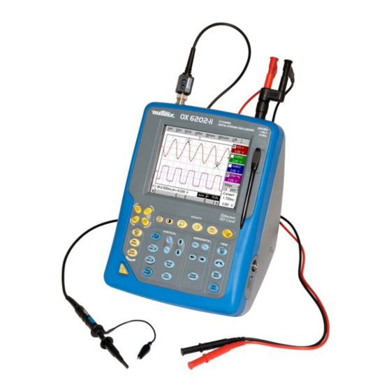
General Instructions General Instructions You have just purchased a 2-channel oscilloscope. Introduction Congratulations on your choice and thank you for your trust in the quality of our products. This range of oscilloscopes offers the following models: color 2-channel 60 MHz 1 GHz sample OX 6062-C color... - Page 5 General Instructions General instructions (cont'd) Precautions and safety measures (cont’d) • Comply with environmental and storage conditions. before use • Check the integrity of the protections and insulation of the accessories. Any item of which the insulation is deteriorated (even partially) must be taken out of service and scrapped.
- Page 6 General Instructions General instructions (cont'd) Warning: Risk of danger. Symbols used on Refer to the operating manual. the instrument Selective sorting of waste for recycling electric and electronic materials. In accordance with the WEEE 2002/96/EC directive: must not be treated as household waste. Earth The CE marking indicates compliance with EC Directives "Low Voltage", "EMC", "DEE"...
- Page 7 General Instructions General instructions (cont'd) For repairs outside continental France, both with and without warranty, Repairs return the appliance to your local Chauvin Arnoux branch or to your under warranty and reseller. outside the warranty Turn the instrument off. • Cleaning Clean it with a damp cloth and soap.
- Page 8 General Instructions I - 8 2-channel Oscilloscopes...
-
Page 9: Description Of The Instrument
Description of the instrument Description of the instrument The adjustment of the 2 ways is accessible by the opposite keys. The OX 6062 and OX 6202 instrument group 4 instruments into one : Presentation • DC voltage measurement • AC voltage measurement Digital Multimeter (RMS) -
Page 10: Front Panel
Description of the instrument Description of the instrument (cont'd) OX 6062 OX 6202 Front Panel II - 10 2-channel Oscilloscopes... - Page 11 Description of the instrument Description of the instrumentDescription of the instrument (cont'd) OX 6062 OX 6202 Rear panel Marking 2-channel Oscilloscopes II - 11...
- Page 12 Description of the instrument Description of the instrumentDescription of the instrument (cont'd) OX 6062 OX 6202 Power supply Interface Marking RS232/Ethernet Extern Socket Trigger Micro SD Card slot Calibration signal II - 12 2-channel Oscilloscopes...
- Page 13 Description of the instrument Description of the instrumentDescription of the instrument (cont'd) Terminal board OX 6062 OX 6152 marking Stylus Magnetized base 2-channel Oscilloscopes II - 13...
- Page 14 Description of the instrument Description of the instrument (cont'd) • The oscilloscopes are designed to operate on a power source delivering 90 Starting up to 264 V (ACrms) at 50 to 60 Hz. • Take the power cord which is in the trunk (p. 12). The power supply can remain in the trunk.
- Page 15 Description of the instrument Description of the instrument (cont'd) 4 "operating mode" keys You can select the operating mode of the instrument by pressing one of these 4 keys: "oscilloscope" "multimeter" (*) "harmonic analyser" (option) "recorder" (option) (*) Measurement ground is connected to earth ground. Shortcut access to the most common functions: see chapter on "The Keys"...
- Page 16 Description of the instrument II - 16 2-channel Oscilloscopes...
-
Page 17: Network
Description of the instrument Description of the instrument (cont'd) The various instrument parameters can be accessed via menus. Using the menus The rules for using, selecting and modifying an option are identical to those defined by Microsoft Windows. To input a numerical value (time base, alignment, etc.), a double click on the numerical field brings up a virtual keyboard: The window title indicates the adjustment in process and the measurement unit... - Page 18 Description of the instrument Description of the instrument (cont'd) An IP address is coded over 4 bytes, displayed in decimal format. IP addresses Example: 132.147.250.10). Each field may be coded between 0 and 255 and is separated by a decimal point. Unlike the physical address, the IP address can be modified by the user.
- Page 19 Description of the instrument Description of the instrument (cont'd) If the result of the operation ' ET LOGIQUE ' between IP address of the SUBNET mask recipient of the message and the value of subnet mask is different from the and GATEWAY address of the recipient of the message, this message is sent to the gateway which will be given the responsibility to forward it to destination.
- Page 20 Description of the instrument II - 20 2-channel Oscilloscopes...
-
Page 21: Micro Memory « Sd Card
Micro SD Memory Card Micro SD Memory Card The internal memory of the oscilloscope (2 MB) may be extended by using an Introduction SD Card (128 MB - 2 GB). The oscilloscope accepts the Micro-SD format (but not Micro-SDHC). The File system supported is FAT12 and FAT16. FAT32 format is not compatible with the oscilloscope. - Page 22 • The oscilloscope sees only the files from this folder. If, at the moment of file saving, the "metrix" folder does not exist, it is automatically created. This type of behaviour is similar to that of digital cameras and is easy to understand.
- Page 23 Micro SD Memory Card Micro SD Memory Card (cont’d) Formatting (French Windows XP example shown) with Windows Insert the SD Card into the SD Card slot of your PC, or using the special USB adapter. Access the workstation window by clicking on: Here, the SD Card is represented...
- Page 24 Micro SD Memory Card Micro SD Memory Card (cont’d) The "Format disk…" window appears: 4. In the "File System" block, select option FAT (not FAT32, which is not compatible with the oscilloscope). Click on: "Start". 5. A message appears, warning that the formatting will delete all data memorised on the SD Card.
- Page 25 Micro SD Memory Card 2-channel Oscilloscopes III - 25...
-
Page 26: Oscilloscope Mode Keys
Oscilloscope Mode - The Keys Oscilloscope Mode The Keys By pressing this key, you can select the "oscilloscope" mode. 5 "UTILITY" keys or key pad Direct access to LCD contrast adjustment. When this key is pressed, the display mode switches from normal to "full screen"... - Page 27 Oscilloscope Mode - The Keys Oscilloscope Mode (cont’d) 4 "Trigger" keys Sets the trigger level to the average value of the signal (50 %) without modifying the trigger coupling. When pressed in combination with a CHx key, this activates the same the same function, after first selecting the corresponding channel as the trigger source.
- Page 28 Oscilloscope Mode - The Keys Oscilloscope Mode (cont'd) 3 "MEASURE" keys activates or deactivates the display of the window for the 20 automatic measurements on the reference trace. When pressed in combination with a CHx key, it displays the measurements concerning the corresponding channel. By means of successive presses, this selects one of the displayed traces as the reference trace for the automatic and manual measurements.
- Page 29 Oscilloscope Mode - The Keys Oscilloscope Mode (cont'd) Validated channel: Display enabled, trace displayed after RUN Definition of terms used Displayed channel: Channel validated, trace present on the screen Selected channel: The parameters of this channel can be set with the keys: 5 "VERTICAL"...
- Page 30 Oscilloscope Mode - The Keys Oscilloscope Mode (cont'd) 5 "VERTICAL" keys or key pads (cont’d) Activates or deactivates horizontal splitting of the display zone. When activated, the "Full Trace" function is indicated by: - the presence of a continuous horizontal line in the middle of the display area - horizontal splitting of the graticule.
-
Page 31: Display
Oscilloscope Mode - Display Oscilloscope Mode (cont'd) Display Display Cursor1 The oscilloscope display is divided into 4 functional zones. Composition Direct access to main settings 4. Menu bar 3. Display area 1. Status area Display and adjustment of current value 2-channel Oscilloscopes IV - 31... - Page 32 Oscilloscope Mode - Display Oscilloscope Mode (cont'd) Three types of general information appear in this area: 1. Status area • The bargraph representing the screen position, the trigger and the cursors in the acquisition memory. • The instrument permanent settings. •...
- Page 33 Oscilloscope Mode - Display Oscilloscope Mode (cont'd) The parameters displayed in this area are: 2. Control area • The parameters of each channel and trace: display, sensitivity, coupling, bandwidth limitation, vertical scale, function, Zoom. • The time base value, the presence of a Zoom and a change in the signal representation domain (FFT).
- Page 34 Oscilloscope Mode - Display Oscilloscope Mode (cont'd) The grouped "Source" and "Trigger Mode" menus can be opened by a double press with the stylus on the time base area. RUN/STOP starts and stops acquisition from this menu. The acquisition status is indicated in the status area on the screen.
- Page 35 Oscilloscope Mode - Display Oscilloscope Mode (cont'd) Display elements > ϕ Definition of display Refs. Elements selectable using the touch-sensitive pad Trace displayed Trace displayed Vertical position indicator of the reference level of the trace displayed and identification of the trace number Indication of Trigger time position Division of graticule Position indicator of the cursors for the first automatic measurement...
- Page 36 Oscilloscope Mode - Display Oscilloscope Mode (cont'd) Menu accessible By double-tapping with the stylus in the from display area display area, the menu concerning the display can be opened directly. The "Full Screen" and "Zoom Out" options are directly accessible (see §.
- Page 37 Oscilloscope Mode - Display Oscilloscope Mode (cont'd) Calibration of the Follow the instructions on the screen touch-sensitive screen (cont'd) Corner of the touch screen Use the stylus to point at the centre of the 4 patterns displayed on the screen. Validation of the input is indicated by modification of the pattern.
- Page 38 Oscilloscope Mode - The "Vertical" Menu Oscilloscope Mode (cont'd) The "Vert" Menu Advanced mode ≠ Advanced mode IV - 38 2-channel Oscilloscopes...
- Page 39 Oscilloscope Mode - The "Vertical" Menu Oscilloscope Mode (cont'd) Opens the "Trace display" menu for validating or devalidating the traces. Display Validation of the selections by "OK". Exit from the menu without modification by "Cancel". The " " symbol in front of a trace indicates that it has been validated. The traces can be validated or devalidated from the control area by using the stylus.
- Page 40 Oscilloscope Mode - The "Vertical" Menu Oscilloscope Mode (cont'd) Modification of the selected channel's vertical scale unit. Measurement unit The modification is performed by means of the stylus, using the table of usable characters after selecting the “measure unit” zone. key deletes the character preceding the cursor in this area.
- Page 41 Oscilloscope Mode - The "Vertical" Menu Oscilloscope Mode (cont'd) math1 math2 For each trace, definition of a mathematical function and the vertical scale. math3 math4 If "Advanced" mode is not activated, simple functions (Inversion, Addition, Subtraction, Multiplication and Division of curves) can be selected and linked to the curves 1 or 2.
- Page 42 Oscilloscope Mode - The "Vertical" Menu Oscilloscope Mode (cont'd) Examples • Predefined divv() function used on its own: math3 = divv(3). Use of predefined mathematical functions The trace is equal to 3 vertical divisions. • Predefined step() function associated with a trace: - math2 = ch1*step(t-divh(4)) The result of math2 is 0 vertical divisions as long as t is less than four horizontal divisions (t-divh(4) <...
- Page 43 Oscilloscope Mode - The "Vertical" Menu Oscilloscope Mode (cont'd) Example 1 Addition of two traces Vhigh Vpp(ch1) = Vpp(ch4) = 6 V Sensitivity (ch1) = 1 V/div Sensitivity (ch4) = 1 V/div Traces ch1 and ch4 are optimised on 6 vertical divisions. Vamp ch1 = 6 vertical divisions Vamp ch4 = 6 vertical divisions - math3 = ch1+ch4...
- Page 44 Oscilloscope Mode - The "Vertical" Menu Oscilloscope Mode (cont'd) Example 2 Multiplication of two traces Sensitivity(ch1) = 5 V/div Sensitivity(ch4) = 5 V/div Vamp(ch1) = Vamp(ch2) = 10 V Vamp ch1 = 2 vertical divisions Vamp ch4 = 2 vertical divisions - math3 = ch1*ch4 As for the addition of traces, there is a even more significant high and low overshoot.
- Page 45 Oscilloscope Mode - The "Vertical" Menu Oscilloscope Mode (cont'd) You can then open the menu “Vertical Scale" of math3 (see §. Opening from math3, math4) to assign a coefficient to the result and to modify the measuring unit. In our example: •...
- Page 46 Oscilloscope Mode - The "Vertical" Menu Oscilloscope Mode (cont'd) - math3 = divv(3)*sin (2*pi*t/500) (∗) Example 3 Association of predefined functions The trace obtained is a sine-curve produced using the predefined function "sin()". The amplitude is 6 divisions. The period equal to 500 samples (∗∗) (2 horizontal divisions) depends on the time base.
- Page 47 Oscilloscope Mode - The "Vertical" Menu Oscilloscope Mode (cont'd) math1 = sin (pi*t/divh(1))*exp(-t/divh(6))*divv(4) Production of an attenuated sine wave using predefined functions "sin (pi*t/divh(1))" can be used to modify the number of periods. "exp (-t/divh(6))" can be used to modify the level of attenuation. 2-channel Oscilloscopes IV - 47...
- Page 48 Oscilloscope Mode - The "Vertical" Menu Oscilloscope Mode (cont'd) contains the list of the functions (.FCT) saved by the user, along with two Files predefined files. By selecting the name of the function with the stylus (function name in blue), you can transfer the definition of the function into the 2 lines provided for that purpose.
- Page 49 Oscilloscope Mode - The "Vertical" Menu Oscilloscope Mode (cont'd) Saves the definition of the function using the “File Copy “ menu (see §. Save Memory Menu). The file is assigned the suffix .FCT and appears in the list of saved files. Reset Completely resets the function definition.
-
Page 50: Trigger" Menu
Oscilloscope Mode - The "Trigger" Menu Oscilloscope Mode (cont'd) The "Trig" Menu IV - 50 2-channel Oscilloscopes... - Page 51 Oscilloscope Mode - The "Trigger" Menu Oscilloscope Mode (cont'd) This range of oscilloscopes is equipped with "advanced triggers". Definition • The "Delay" and "Count" trigger modes require parameterization of a second "auxiliary" trigger source. The auxiliary source may be the same as the main source.
- Page 52 Oscilloscope Mode - The "Trigger" Menu Oscilloscope Mode (cont'd) Selection of the "Trigger Parameters". Parameters Trigger on edge Main selects a channel as a trigger source. Source Selection of the filter for the main trigger source: Coupling AC coupling (10 Hz to 200 MHz): blocks the DC component of the signal DC coupling (0 to 200 MHz): allows the entire signal through...
- Page 53 Oscilloscope Mode - The "Trigger" Menu Oscilloscope Mode (cont'd) Signal injected on CH1: a train of three 6 V pulses at a frequency of 20 kHz Example with a 500 mV component, separated by 500 µs. The trigger is regulated with channel 1 as a source, level at 2.04 V, on a rising edge.
- Page 54 Oscilloscope Mode - The "Trigger" Menu Oscilloscope Mode (cont'd) Trigger selection on pulse width. Pulse In all cases the effective triggering occurs on the end of pulse edge. triggers if pulse duration is greater than specified value T1 t > T1 triggers if pulse duration is less than specified value T1 t <...
- Page 55 Oscilloscope Mode - The "Trigger" Menu Oscilloscope Mode (cont'd) Selection of edge trigger with delay Delay The delay is triggered by the auxiliary source. Effective triggering occurs after the end of the delay on the next event from the main source. 35.2µs Adjustment with the stylus using the setting scroll bar to choose the Trigger delay...
- Page 56 Oscilloscope Mode - The "Trigger" Menu Oscilloscope Mode (cont'd) Signal injected on CH1: a train of three 6 V pulses at a frequency of 20 kHz Example separated by 500 µs. The trigger is active after the end of the delay (35.2 µs) on the first ascending edge.
- Page 57 Oscilloscope Mode - The "Trigger" Menu Oscilloscope Mode (cont'd) Selects the edge trigger with counting of events. Count The count is triggered by the auxiliary source. The main source serves as a clock for the count. Effective triggering occurs after the end of the count on the next event from the main source.
- Page 58 Oscilloscope Mode - The "Trigger" Menu Oscilloscope Mode (cont'd) Example Signal injected on CH1: a train of five 6 V pulses at a frequency of 20 kHz separated by 500 µs. The trigger is set on the descending edge. The first edge activates the trigger. It is not included in the count. The trigger is triggered on the third descending edge of the pulse train.
- Page 59 Oscilloscope Mode - The "Trigger" Menu Oscilloscope Mode (cont'd) Trigger on a TV signal See Chapter VI - Applications: §. Video signal display. This menu is only applicable to the CH1 input. Trigger on a specific line number. The trigger starts on the front edge of the line Standard synchronization signal.
-
Page 60: Menus
Oscilloscope Mode - The "Trigger" Menu Oscilloscope Mode (cont'd) Acquisitions and refreshment of the screen at each trigger event. Triggered mode Acquisition and automatic refreshing of screen even when there is no trigger Automatic mode event. Visible traces, even when there is no trigger event. Acquisition of signal and refreshing of the screen on the first trigger occurring Single mode and after a trigger reset by pressing the key opposite (or via the time base menu). - Page 61 Oscilloscope Mode - The "Horizontal" Menu Oscilloscope Mode (cont'd) The "Horiz" Menu (∗) (∗) (∗) Function accessible only in "Advanced" mode. See §. Description, page 82. Increase in the time definition of a trace for a periodic signal. If this option Repetitive Signal is valid, the signal can be averaged (see below).
- Page 62 Oscilloscope Mode - The "Horizontal" Menu Oscilloscope Mode (cont'd) Use this mode to view the extreme values of the signal acquired between Min/Max 2 acquisition memory samples. Acquisition This mode: detects wrong representation due to under-sampling • displays short-term events (Glitch, ≥ 2 ns). •...
- Page 63 Oscilloscope Mode - The "Horizontal" Menu Oscilloscope Mode (cont'd) Square signal FFT with a Hanning window and a log FFT with a rectangular window and a scale linear scale This is indicated instead of the time base and is calculated according to the Horizontal unit scanning coefficient: 12.5...
- Page 64 Oscilloscope Mode - The "Horizontal" Menu Oscilloscope Mode (cont'd) The sub-menus select a type of window. Rectangular Hamming Hanning Blackman Flat Top Before calculating the FFT, the oscilloscope weights the signal to be analyzed by means of a window acting as a band-pass filter. The choice of window type is essential to distinguish between the various lines of a signal and to make accurate measurements.
- Page 65 Oscilloscope Mode - The "Horizontal" Menu Oscilloscope Mode (cont'd) The finite duration of the study interval results in a convolution in the signal frequency domain with a function sinx/x. This convolution modifies the graphic representation of the FFT because of the lateral lobes characteristic of the sinx/x function (unless the study interval contains an whole number of periods).
- Page 66 Oscilloscope Mode - The "Display" Menu Oscilloscope Mode (cont'd) The "Display" Menu (∗) (∗) Function only accessible in "Advanced" mode. See §. Description, page 82. Display / Removal of graticule Grid Display modes A vector is plotted between each sample. Vector The minimum and maximum observed on each horizontal position of the Envelope...
- Page 67 Oscilloscope Mode - The "Display" Menu Oscilloscope Mode (cont'd) Switches from the normal display mode to the “full screen” display mode and Full screen vice versa. The display is organized so as to leave the biggest surface area possible for trace plotting: only the permanent settings and the automatic or manual measurements remain.
-
Page 68: Measurement" Menu
Oscilloscope Mode - The "Measure" Menu Oscilloscope Mode (cont'd) The "Measure" Menu (∗) (∗) Function only accessible in "Advanced" mode. See §. Description, page 82. Selection of the trace on which the automatic or manual measurements Reference will be performed. Trace 1 Trace 2 Only the active traces can be selected. - Page 69 Oscilloscope Mode - The "Measure" Menu Oscilloscope Mode (cont'd) • It is possible to select two permanent measurements. • The " " symbol indicates the measurement(s) that will be indicated in the status area. • Activation of the automatic measurements causes two markers (+) to appear on the curve, if at least one period is visible on the screen.
- Page 70 Oscilloscope Mode - The "Measure" Menu Oscilloscope Mode (cont'd) The measurements are performed on the displayed part of the trace. • Measurement conditions Any change to the signal will lead to updating of the measurements. • They are refreshed in step with acquisition. To perform automatic measurements on specific portions of the signal, •...
- Page 71 Oscilloscope Mode - The "Measure" Menu Oscilloscope Mode (cont'd) Automatic measurement of a trace's phase compared with a reference trace Phase measurement (See §. Reference Measurement). Trace1 Phase This menu selects the trace on which phase measurements are to be Trace2 Phase performed.
- Page 72 Oscilloscope Mode - The "Measure" Menu Oscilloscope Mode (cont'd) Used for linking or not linking the manual measurement cursors (1 and 2) Unattached manual to the reference trace. cursors When the "Unattached cursors" menu is selected, cursors 1 and 2 can be moved freely over the whole screen.
- Page 73 Oscilloscope Mode - The "Memory" Menu Oscilloscope Mode (cont'd) The "Memory" Menu Storage of the selected trace in its reference memory Trace 1 Ref. 1 E.g.: Trace 1 in Ref. 1). Trace 2 Ref. 2 Trace 3 Ref. 3 The 4 traces have their reference memory. Trace 4 Ref.
- Page 74 Oscilloscope Mode - The "Memory" Menu Oscilloscope Mode (cont'd) Saving (to the non-volatile memory) or recall of a trace or a reference Trace memory. The back-up can be saved in two formats: ".TRC" or ".TXT". The "File copy" menu is adapted to the type of format selected. Saving of the files for subsequent recall on the oscilloscope screen Save .TRC The back-up files will take the suffix .TRC;...
- Page 75 Oscilloscope Mode - The "Memory" Menu Oscilloscope Mode (cont'd) When selected, this opens a "File Copy" menu. Recall .TRC In the "Source" list, the .TRC files previously saved (via the menu "Trace Save .TRC") are displayed. Select the file to be called up from the list displayed. ∗...
- Page 76 Oscilloscope Mode - The "Utilities" Menu Oscilloscope Mode (cont’d) The"Util" Menu IV - 76 2-channel Oscilloscopes...
- Page 77 Oscilloscope Mode - The "Utilities" Menu Oscilloscope Mode (cont'd) Selection of the "File Management" menu. It contains the files which have been: Files • saved in previous sessions • created since the last instrument startup. • The storage capacity of the file system is 2 Mbytes. These files will be saved in the FLASH memory when the instrument is switched off with the button opposite: they will then be available for the next session.
- Page 78 Oscilloscope Mode - The "Utilities" Menu Oscilloscope Mode (cont'd) I/O port config In the "USB / RS232" window, check the USB Cable button. This interface uses the (USB / RS232 / ETHERNET) connector on the right side of the equipment. The HX0084 cable must be used. The HX0084 cable converts the RS232 format output from the instrument to the USB protocol.
- Page 79 Oscilloscope Mode - The "Utilities" Menu Oscilloscope Mode (cont’d) Configuration of the ETHERNET parameters Network If this box is checked, the instrument makes a request to the network provided by a DHCP server to automatically obtain: DHCP server • an IP address •...
- Page 80 Oscilloscope Mode - The "Utilities" Menu Oscilloscope Mode (cont'd) Name of the printer as it appears in the printing server (or PC). Name If the printer is connected directly to the network, do not enter anything here. This key can only be accessed in Advanced mode. Use this function to manually configure: •...
- Page 81 Oscilloscope Mode - The "Utilities" Menu Oscilloscope Mode (cont'd) The print format, the type of printer and the communication port are chosen from Hardcopy this menu. The print format should be selected from the list using the stylus. Use the scrollbar to the right of the list to view all the printer languages available.
- Page 82 Oscilloscope Mode - The "Utilities" Menu Oscilloscope Mode (cont'd) Display of data concerning the operation of the instrument since it was first System info used. This list displays the result of the self-test activated when the instrument is Autotest switched on. For verification of the instrument, see §.
- Page 83 Oscilloscope Mode - The "Utilities" Menu Oscilloscope Mode (cont'd) Use the "Image Viewer" to display .GIF and .BMP files from a screen grab. "Image Viewer" of .GIF and .BMP files The " Image Viewer " can be accessed from the file manager by opening a .GIF or .BMP file.
- Page 84 Oscilloscope Mode Oscilloscope Mode (cont'd) The « ? » Menu OX6202, V.2.14/AA When selected with the stylus, this opens the "Help" menu. Help The online help concerns the instrument's keyboard. Use the keys to scroll through the description of the keys on the front panel.
- Page 85 On the name of the instrument, the software version and the version of the hardware the WEB site to visit to find new products in the range for METRIX instruments. the email address of the customer service that can answer your questions on the instrument.
-
Page 86: Multimeter Mode
Multimeter Mode - The Keys Multimeter Mode The Keys Press the key opposite to select the "Multimeter" mode. 4 "UTILITY"keys or key pads Direct access to LCD light adjustment. No action. Triggers a hardcopy in accordance with the configuration chosen in the "Util" and "Hardcopy"... - Page 87 Multimeter Mode - The Keys Multimeter Mode (cont'd) 3 "MEASURE" keys No action. For changing the reference trace to which the cursor refers (successive presses). No action. 3 "HORIZONTAL" keys or key pads Duration of the recording in the display window: > 5’, 15’, 30’, 1h, 6h, 12h, 24h, week, month.
-
Page 88: Display
Multimeter Mode - Display Multimeter Mode (cont'd) Display Display The multimeter display is divided into 6 functional areas: Composition 1. Menu bar 2. Ch. 1 Multimeter 3. Cursor value 5. Graphic window 2. Ch. 2 Multimeter 6. Current setting 1. Menu bar The tool bar gives access to the different menus of the "Multimeter"... - Page 89 Multimeter Mode - Display Multimeter Mode (cont'd) There is a display area reserved for each of the instrument's channels. In each 2. Channel (x) of these, the following information is indicated: multimeter) Auto- Symbol Coupling Channel Symbol ranging Unit Unit Principal measurement Principal measurement Secondary measurement...
- Page 90 Multimeter Mode - Display Multimeter Mode (cont'd) These graphs show the min. and max. values measured on the channels in the 4. Bargraph range during the observation period. The bargraph is shown with the colour of the channel. The zero level of the bargraph and the scale are adapted to suit the type of measurement and the range.
-
Page 91: Menus
Multimeter Mode - The Menus Multimeter Mode (cont'd) The Menus Presentation • Screen display when measurements are possible on 2 channels: Example: Resistance measurement on CH1 channel and amplitude measurement on other channels • Screen display when measurements are possible on CH1 only: Example: CH1 is configured for a Component Test The display is identical when CH1 is configured for capacitance or continuity measurement. - Page 92 Multimeter Mode - The "Vertical" Menu Multimeter Mode (cont'd) The "Vert" Menu Modification of: ch1 ch4 the parameters of channels ch1 and ch4, independently • the vertical scale of the selected trace • Modifies the parameters of the selected channel. Sensitivity/Coupling Each measurement display zone on the main screen indicates the coupling and bandwidth limitation parameters used on each channel.
- Page 93 Multimeter Mode - The "Vertical" Menu Multimeter Mode (cont'd) When this option is selected, the measurement range changes Autorange automatically. The " " symbol shows that it is active. The range can be modified manually, using the keys opposite or the "Range"...
- Page 94 Multimeter Mode - The "Trigger", "Horizontal" and "Display" Menus Multimeter Mode (cont’d) The "Trig" Menu The detailed analysis of the signal allows you to search and record events. Source/Level The defined levels are instantaneous values (they are not effective values). Selection of trigger type and level on each channel.
-
Page 95: Display" Menu
Multimeter Mode - The "Trigger", "Horizontal" and "Display" Menus Multimeter Mode (contd.) The "Horiz" Menu • If this mode is activated (presence of " " symbol), the measurement Roll history curve is constructed continuously. The oldest points disappear on the left-hand side of the screen, while the most recent ones appear on the right. - Page 96 Multimeter Mode - The "Trigger", "Horizontal" and "Display" Menus Multimeter Mode (contd.) In the event of alternative amplitude, display of the frequency of the signal Frequency measured (if possible and coherent) as a secondary measurement on each channel. Display of the Min and Max values of the measurements taken as Statistics secondary measurements on each channel.
- Page 97 Multimeter Mode - The "Measure" Menu Multimeter Mode (cont'd) The "Measure" Menu Do not use any oscilloscope probe for following measurements: Ohmmeter Continuity Capacimeter Test Component The reference is used to select the measurement trace on which the cursor is Reference positioned.
-
Page 98: Memory" Menu
Multimeter Mode - The "Memory", "Utilities" and "Help" Menus Multimeter Mode (cont'd) The "Memory" Menu In "Multimeter" mode, it is only possible to save a trace in non-volatile memory Trace (.TXT) in .TXT format. Files saved with the suffix .TXT can be exported onto a PC (see §. Util Menu iles) for processing with other software (spreadsheet, etc.). -
Page 99: Help " Menu
Multimeter Mode - The "Memory", "Utilities" and "Help" Menus Multimeter Mode (cont'd) This menu is identical to the one in "Oscilloscope" mode, except : The "Util" Menu Configuration • If the recording time is equal or over 15 minutes, the screen saver will never Screen saver be activated. - Page 100 Multimeter Mode V - 100 2-channel Oscilloscopes...
-
Page 101: Harmonic Analysis Mode
Harmonic Analysis Mode - Display Harmonic Analysis Mode The "Harmonic Analysis" mode is an option of the oscilloscope which must be Display unlocked if it is to function. The 24-character code supplied when the "HARMONIC ANALYSER" option is Installation acquired must be input into the " ? " "Options"... - Page 102 Harmonic Analysis Mode - Display Harmonic Analysis Mode (cont'd) In this mode, the display is divided into 4 functional areas: Composition 4. Menu bar Direct access to main settings 1. Display area Selection of the fundamental or a harmonic Display of information on Display of 3.
- Page 103 Harmonic Analysis Mode - Display Harmonic Analysis Mode (cont'd) 2. Control area Using the stylus, display of: the parameters of the traces in the same colour as the trace: validity, coupling, bandwidth limit, sensitivity • When the pointer is placed on one of a channel's parameters, it directly opens the associated "Sensitivity/Coupling"...
- Page 104 Harmonic Analysis Mode - The "Vertical" Menu Harmonic Analysis Mode (cont'd) The "Vert" Menu When selected, this opens the "Trace display" menu for validating or Display invalidating the traces. Validation of the selections by "OK". Exit from the menu without modification by "Cancel".
- Page 105 Harmonic Analysis Mode - The "Vertical" Menu Harmonic Analysis Mode (cont'd) Modification of the parameters of ch1 or ch4, independently. ch1 ch4 Sensitivity/Coupling Modification of the channel's sensitivity using the stylus on the scrollbar: Channel Sensitivity from 2.5 mV to 100 V/div. The sensitivity is indicated in the channel parameter display area.
- Page 106 Harmonic Analysis Mode - The « Horizontal » Menu Harmonic Analysis Mode (cont'd) The "Horiz" Menu In "Automatic fundamental frequency search" mode, the instrument Fundamental freq: AUTO analyses the signal on the range Fundamental freq: ~50Hz [40Hz 1kHz]. Fundamental freq: ~60Hz If this search is not successful, you can indicate one of three Fundamental freq: frequencies proposed to the instrument.
-
Page 107: Display" Menu
Harmonic Analysis Mode - The « Display » - « Memory » - « Util » - « Help » Menus Harmonic Analysis Mode (cont'd) The "Display" Menu These menus allow you to view the harmonic composition of one or more selected signals, according to 3 groups. - Page 108 Harmonic Analysis VI - 108 2-Channel Oscilloscopes...
- Page 109 Recorder Mode - Keys Recorder Mode The Keys This key selects “Recorder” mode. 5 "UTILITY" keys (or keypad) LCD light setting (see “Oscilloscope” mode). Full screen display (see “Oscilloscope” mode). Take a screen shot (see “Oscilloscope” mode). No action. (Pressing this key displays the message: “Impossible in this mode!”. 1 "AUTOSET"...
- Page 110 Recorder Mode - Keys Recorder Mode (cont’d) 3 "MEASURE" keys The 20 automatic measurements of the reference trace are displayed (see “Oscilloscope” mode). Particular case In “fault capture” mode, if the screen shows several faults at once, the “automatic measurement” function is impossible and the message “Impossible in this mode!”...
-
Page 111: Keys
Recorder Mode - Keys Recorder Mode (cont’d) 5 "VERTICAL" keys (or keypads) Stage 1 Stage 2 Stage 3 Before pressing one of the After pressing one of these Press keys shown opposite: keys: The signal concerned is not The signal is displayed and is displayed. -
Page 112: Display
Recorder Mode - Display Recorder Mode (cont’d) Display Normal mode display The user views 500 points on the screen (in “MIN/MAX” mode) to eliminate the risk of information loss involving the 50,000 points in the memory. Display in fault capture mode The memory is segmented to enable the acquisition of... - Page 113 Recorder Mode - Display Recorder Mode (cont’d) Three pieces of general information appear in this area: 1. Status area • The bargraph, representing the screen position and the cursors in the acquisition memory; • Instrument settings (fault capture mode, zoom, etc.); •...
- Page 114 Recorder Mode - Display Recorder Mode (cont’d) In fault capture mode, the bargraph indicates the position of the screen and Bargraph cursors in the acquisition memory. The main cursor is positioned on the displayed fault and the auxiliary cursor on the right of the screen.
- Page 115 Recorder Mode - Display Recorder Mode (cont’d) 2. Control area (cont.) Measurement of sample The colour corresponds under auxiliary cursor to the colour of the trace. Display of trace Measurement of sample parameters: under main cursor - validity - DC coupling - bandwidth limit - vertical measurement of sample under cursors...
- Page 116 Recorder Mode - Display Recorder Mode (cont’d) Graphic elements displayed associated with the traces in this area: 3. Display area • Vertical position indicator for the reference level of each trace • ZOOM area selection. • Main cursor (permanent, moved using stylus) located at the left of the screen by default.
- Page 117 Recorder Mode - Display Recorder Mode (cont’d) Display elements Items Display elements Definition of display Trace displayed Indication of vertical position of reference level of the displayed Trace displayed trace and identification of trace number Indicator of trace outside display window Graticule division Zoom area selection Main measuring cursor...
- Page 118 Recorder Mode - Display Recorder Mode (cont’d) Like in “Oscilloscope” mode, the menu concerning the display can be opened Menu accessible directly by double-tapping with the stylus in the display area. from display area This menu, as well as the functions of the proposed options, are identical to those in “Oscilloscope”...
- Page 119 Recorder Mode - Display Recorder Mode (cont’d) The horizontal zoom is enabled, the screen displays one of the captured faults: Case 2 Fault capture mode: the horizontal zoom is enabled. A single fault is displayed on the screen. A zoom frame is drawn.
- Page 120 Recorder Mode - The « Vertical » Menu Recorder Mode (cont’d) This menu is identical to that described in “Oscilloscope” mode. The "Vert" Menu (∗) in « Advanced » mode : in ≠ « Advanced » mode : (∗) The DC coupling is the only option in “Recorder”...
-
Page 121: Trigger" Menu
Recorder Mode - The “Trigger” Menu Recorder Mode (cont’d) The "Trig" Menu Selection of trigger type and level on each channel. Triggering takes place if a Triggering condition described by a line of the “Trigger” table is verified. The trigger level should be defined in the channel measurement dynamic. Indicates the channel number. - Page 122 Recorder Mode - The “Trigger” Menu Recorder Mode (cont’d) “No trigger”: if all the channels are in this mode, the device records indefinitely. • “Lower than”: triggering takes lower place when the signal drops triggering threshold below the threshold. • “Lower/higher than”: triggering threshold takes place when the signal...
- Page 123 Recorder Mode - The “Trigger” Menu Recorder Mode (cont’d) Delayed triggering offers the possibility of starting up an acquisition at a date Delayed triggering and time chosen by the user. This option can be related to the previous trigger conditions. This tab allows the user to validate –...
- Page 124 Recorder Mode - The “Trigger” Menu Recorder Mode (cont’d) In 'Fault capture' mode, records are saved to the file as soon as 10 faults (or Fault capture 100 faults with the EXTENDED ACQUISITION MEMORY) have been acquired. (cont’d) You can therefore save several acquisitions and analyse them later The channels are saved in files, the name of which is determined according to the date and time they are saved.
- Page 125 Recorder Mode - The “Trigger” Menu Recorder Mode (cont’d.) Two cases arise: Display (fault capture, the horizontal zoom is disabled, • file capture) the horizontal zoom is enabled. • Modification of display: Horizontal zoom disabled The cursors are no longer displayed. •...
-
Page 126: Horizontal" Menu
Recorder Mode - The “Horizontal” Menu Recorder Mode (cont’d) The "Horiz" Menu This function allows the user to set: Horizontal scale - the recording time, - the acquisition interval. These two values are correlated. When the user modifies one, the other is modified. - Page 127 Recorder Mode - The “Display” Menu Recorder Mode (cont’d) The "Display" Menu Returns to the original screen size after zooming in on part of the screen. Zoom off • This function is disabled unless the screen is in zoom mode. •...
- Page 128 Recorder Mode - “Display” Menu Recorder Mode (cont’d) The search for faults enables successive recorderings in “fault capture” or Faults “file capture” (memory) mode to be explored (.REC). All files with a “.REC” extension are analysed and each fault is displayed. When one of these faults is selected, it is displayed on the screen.
-
Page 129: Measurement" Menu
Recorder Mode - The “Measurement” Menu Recorder Mode (cont’d) The "Measure" Menu Reference Identical to “Oscilloscope” mode. Trace 1 Trace 2 Trace 3 Trace 4 This window is nearly identical to the one in "Oscilloscope" mode. Automatic measurements The automatic measurement calculation area is defined by the two cursors. It is not possible to select measurements in order to display them in the status area. - Page 130 Recorder Mode - The “Memory” Menu Recorder Mode (cont’d) The "Memory" Menu Trace In this mode, all the traces are saved in one file (extension .REC). Save .REC The selection opens a "File Copy" menu. A default backup filename is proposed above the keyboard. It can be modified using the virtual keyboard and stylus.
- Page 131 Recorder Mode - The “Memory” Menu Recorder Mode (cont’d) Identical to “Oscilloscope” mode (see §. Memory Menu Trace Save ‘.TXT’). ‘.TXT’ save In this mode, traces are saved individually. Description of deltaX= 4e-05 the information Vertical unit: V, Coupling: DC Time difference between measurements in a .TXT file -1.54e+00...
- Page 132 Recorder Mode - The “Memory” Menu Recorder Mode (cont’d) Example Saving a ‘.REC’ acquisition: Enter the filename. Then click on to validate the save. Recall ‘.REC’: Select the file to recall. Then click on to validate your choice. Mx symbol: all the traces come from the memory.
- Page 133 Recorder Mode - The “Memory” Menu Recorder Mode (cont’d) Saving or recalling an instrument configuration. Configuration Opens a "File copy" menu when selected. Save ∗ There is a file called “Configuration” in the “Source” list. It contains the configuration settings for the device at the time this menu is opened.
-
Page 134: Utilities" Menu
Recorder Mode - The “Utilities” Menu Recorder Mode (cont’d) The"Util" Menu VII - 134 2-channel Oscilloscopes... - Page 135 Recorder Mode - The “Utilities” Menu Recorder Mode (cont’d) This function is identical to that described in “Oscilloscope” mode. File manager Identical to “Oscilloscope” mode. I/O port config Identical to “Oscilloscope” mode. Hardcopy Identical to “Oscilloscope” mode. Configuration • If the recording time is over 2 seconds, the screen saver will never be Screen saver activated.
-
Page 136: Help" Menu
Recorder Mode - “Help” Menu Recorder Mode (cont’d) The "?" Menu OX 6202, V.2.14/AA Menu identical to “Oscilloscope” mode. Help Menu identical to “Oscilloscope” mode. About Menu identical to “Oscilloscope” mode. Options VII - 136 2-channel Oscilloscopes... - Page 137 Recorder Mode SCOPIX VII - 137...
-
Page 138: General
HTTP and FTP Server 1 - General Minimum PC configuration: Pentium 4, 1GHz, RAM: 1 Go. Screen resolution: > 1152 x 864 pixels Install JVM SUN J2RE 1.6.0 (or a more recent version) from the //www.java.com site Recommended browsers: Microsoft Explorer 7 (or a more recent version), Mozilla Firefox 3 (or a more recent version) -
Page 139: Scopenet
HTTP and FTP Server 2 - ScopeNet The screens described below are in English but the language actually used Presentation in your environment depends on the configuration of your PC (Windows XP, see the Control Panel, Regional and Language Options). There is also a version of ScopeNet for Android tablets and smartphones (download from GOOGLE PLAY STORE). - Page 140 HTTP and FTP Server 2 - ScopeNet (cont’d) If you get the following error message when connecting: Your PC does not run this applet. In this case, you must use the "policytool" located in the installation directory of Java (see page 152). With this tool, you will configure your PC to allow the execution of applets.
- Page 141 HTTP and FTP Server 2 - ScopeNet (cont’d) The ScopeNet operating mode is almost identical to the instrument Client configuration operating mode. The few ScopeNet specificities are described in this chapter. Access to an external FTP server The use of an external FTP server is optional. The external FTP server can be a PC on which the Filezilla Server software (see p.
- Page 142 HTTP and FTP Server 2 - ScopeNet (cont’d) Possibilities using this mode: "OSCILLOSCOPE" Visualisation of the curves as they are displayed on the instrument Mode Adjustment of all vertical, horizontal settings, ... Measures by cursor, relative to a reference curve Automatic measurements (using samples located between the cursors) measurements...
- Page 143 HTTP and FTP Server 2 - ScopeNet (cont’d) Automatic measurements Selecting the reference channel Automatic measurements on the reference channel The signal zone used for automatic measurements is bounded by cursors 1 and 2. 2-channel Oscilloscopes VIII - 143...
- Page 144 HTTP and FTP Server 2 - ScopeNet (cont’d) Zoom Selection of the zone to zoom on using the mouse Result of the zoom operation To deactivate the zoom uncheck the 'Zoom’ check box on the 'Display’ menu VIII - 144 2-channel Oscilloscopes...
- Page 145 HTTP and FTP Server 2 - ScopeNet (cont’d) Possibilities using this mode: "FFT" Mode Visualisation of the curves as they are displayed on the instrument Setting of various parameters Measures by cursor, relative to a reference curve The boundary indicators show - 40 dBV 2-channel Oscilloscopes VIII - 145...
- Page 146 HTTP and FTP Server 2 - ScopeNet (cont’d) Possibilities using this mode: "MULTIMETER" Mode Visualisation of the curves as they are displayed on the instrument Adjustment of all acquisition settings, ... Measurements by cursor, relative to a reference curve Horizontal zoom to view the last 2700 measurements (if the instrument has the EXTENDED...
- Page 147 HTTP and FTP Server 2 - ScopeNet (cont’d) Possibilities using this mode: "RECORDER" Mode Visualisation of the curves as they are displayed on the instrument Adjustment of all the instrument settings Measurements by cursor, relative to a reference curve Automatic measurements (using samples located between the cursors) Reference curve used View/Clearing of the...
- Page 148 HTTP and FTP Server 2 - ScopeNet (cont’d) Possibilities using this mode: "HARMONICS Analysis" mode Harmonic analysis of the signals connected to the instrument channels Calculation of 64 harmonics and View of 32 harmonics (even or odd, or the first or the last) Adjustment of all the instrument settings Automatic measurements with a selection of the reference harmonic Automatic measurements (using samples located between the cursors)
-
Page 149: Scopeadmin
HTTP and FTP Server 3 - ScopeAdmin It is a utility for supervising a set of METRIX instruments that support a ScopeAdmin specific communications protocol. It is an applet that must be run on an instrument server client machine (PC or other). - Page 150 HTTP and FTP Server 3 - ScopeAdmin (cont’d) If you get the following error message when connecting: Your PC does not run this applet. In this case, you must use the "policytool" located in the installation directory of Java (see page 152). With this tool, you will configure your PC to allow the execution of applets.
- Page 151 HTTP and FTP Server 3 - ScopeAdmin (cont’d) Screen displayed after "Find Instruments" is run A right mouse click in the title bar displays a context menu, the actions generated from this menu cover all the instruments in the list. A right mouse click in a line for a specific instrument...
-
Page 152: Policytool
HTTP and FTP Server 4 - Policy Tool Configuration of the • ScopeAdmin uses the oscilloscope UDP 50000 port. client machine (PC) • On your PC you can change the applet operation authorisation file in order to allow ScopeAdmin to run: Run the policytool utility from the JAVA installation directory (e.g.: C:\Program Files\Java\jre1.6.0_07\bin). -
Page 153: Ftp Server
To access the internal files of the instrument, enter the following URL into the address bar of your browser: ftp://<instrument IP address>/RAM:/ To access the files in the SD Card of the instrument, enter the following URL into the address bar of your browser: ftp://<instrument IP address>/CARD:/metrix/ 2-channel Oscilloscopes VIII - 153... -
Page 154: Display Of The Calibration Signal
Applications Applications 1. Display of the calibration signal • Using the key shown opposite, select the "Oscilloscope" mode. • Connect a 1/10-ratio probe to input CH1. • Via the probe (with its earth) connect the calibrator output to input CH1 (Probe Adjust: ≈... - Page 155 Applications Applications (cont’d) If necessary: • Modify the trigger level using the stylus: - by moving the symbol T (Trigger) on the screen. The value of the trigger level is indicated in the bottom right-hand corner of the screen. - or through the trigger parameters menu: Trig.
-
Page 156: Automatic Measurements
Applications Applications (cont’d) 2. Automatic measurement • Connect the calibrator output (3 V, 1 kHz) in the connection zone to input CH1, using a 1/10 measurement probe. • For probe adjustments, see the §. Calibration signal display. • Opt for: 500 mV/div. vertical calibre, time base coefficient 500 µs/div. -
Page 157: Automatic Phase Measurement
Applications Applications (cont’d) • Select measurement by cursors using the menu: 3. Measurement Measure Manual measurements (dt, dv) (see §. Measure Menu). using cursors ∗ Two measurement cursors (1 and 2) are displayed as soon as the menu has been activated. ∗... -
Page 158: Manual Phase Measurement
Applications Applications (cont’d) • Select manual phase measurement via the menu: 6. Manual measurement Measure Manual phase measurement (see §. Measure Menu). of phase ∗ The 2 cursors (1 and 2) of the manual measurements are displayed on the reference trace. A "ϕ" cursor in relation to which the phase is measured is displayed. - Page 159 Applications Applications (cont’d) • Select the trigger mode: Trig. Menu Automatic mode or using the SGLE REFR key. • Use the RUN HOLD key to start acquisition (RUN mode) or use the time base menu. The acquisition status (Ready, RUN, STOP) is indicated on the right, under Reminder the display of the trace, in the trigger status display zone.
-
Page 160: Examination Of A Specific Tv Line
Applications Applications (cont’d) For more detailed examination of a video line signal, the TV trigger menu can 8. Examination of a specific TV line be used to select a line number. • In the Trigger Parameters menu, select the tab: Trig. - Page 161 Applications Applications (cont’d) Initially, there must be one or two traces on channels CH1 and CH4. 9. Automatic measurement in Harmonic Analysis mode - Only the channels (and not the functions) can be the subject of Recall harmonic analysis. - In this mode, the time base is not adjustable. •...
- Page 162 Applications Applications (cont’d) • The Table "Ref.: Harmonic X" indicates, for the harmonic selected: - its value as a % of the fundamental - its phase in ° with respect to the fundamental - its frequency in Hz - its RMS voltage in V Example of harmonic breakdown •...
- Page 163 Applications Applications (cont’d) This example examines the analysis of slow phenomena for time bases ranging 10. Display of slow from 200 ms to 200 s. The samples are displayed constantly, without waiting for phenomena “ROLL” the Trigger (ROLL mode). mode Examination of slow phenomena over a significant period of time •...
-
Page 164: Min/Max Acquisition
Applications Applications (cont’d) Detection of a wrong representation due to under-sampling 11. Min / Max Acquisition Examination of an amplitude-modulate signal • Using the key shown opposite, select the "Oscilloscope" mode. • Inject on the CH1 input an amplitude-modulated sinusoidal signal at a. frequency of 15Hz. - Page 165 Applications Applications (cont’d) The observation of the amplitude-modulated CH1 trace cannot be used (incorrect display). • Validate the MIN / MAX mode: Horiz MIN/MAX Acquisition menu, to view the amplitude modulation of the CH1 signal. Examination of the signals 2-channel Oscilloscopes IX - 165...
-
Page 166: Measurement In Multimeter Mode
Applications Applications (cont’d) 12. Measurement in multimeter mode • Press the key opposite to activate the "Multimeter" mode. • Connect the signal on the CH1 input. Measurement in Multimeter Mode • Configure the oscilloscope in Ohmmeter mode: Menu: Measurement Ohmmeter. •... - Page 167 Applications Applications (cont’d) Example of measurement in Multimeter Mode The graphic window records the changes in the measurements during the analysis period (5 minutes). The bargraph shows the amplitude of the variations. The minimum value (49.9 ohms) and the maximum value (550.5 Ohms) measured are indicated in the CH1 parameter display.
-
Page 168: Ethernet Network Application Examples
A list of the files is then displayed. If an SD Card is present, the entire memory of the SD Card is displayed on the FTP server and not only the specific "metrix" folder. • You can use your browser to:... - Page 169 Applications Applications (cont’d) Screen copying can be initiated on a network printer. b) Hard copy of the screen on a network printer Printer Oscilloscope IP Address = IP Address = 132.147.200.10 132.147.200.74 ETHERNET network • Use a suitable ETHERNET cable to link the oscilloscope to the network. •...
- Page 170 Applications Applications (cont’d) This application note is designed to make an FTP server function (FileZilla c) Installation of an server) in basic mode on your PC. You will find more explanations on the FTP server on a PC configuration and use of this server on the site "sourceforge.net/projects/filezilla".
- Page 171 Applications Applications (cont'd) 5. In the Edit menu, click on Users to display the following: 6. Click on "Add”, and the window “Add user account” will appear: 7. Create a user. 8. Click on "OK". 2-channel Oscilloscopes IX - 171...
- Page 172 Applications Applications (cont'd) 9. In the “Page” list, click on the option “Shared folders”, in the top left: 10. Using the "Add" button under the "Shared folders” window, choose a directory on the disk in which the “user” can read and write files from oscilloscope.
- Page 173 Applications Applications (cont'd) Oscilloscopes settings 15. Go into advanced mode “Util” "Advanced Mode” 16. Open the menu “Util” “Config I/O Ports” “Network” 17. Click twice on the button ".../…” 18. Configure the FTP server (IP address of the PC on which the fileZilla Server was installed, user name and password if it has been defined).
-
Page 174: Virtual Printers
Virtual Printers Windows 2000, XP or Vista. It manages METRIX oscilloscope printouts via an ETHERNET Connection. Your PC becomes a LPD server and the oscilloscopes are its clients. This server manages all printing for the clients on the printers that are connected to it. - Page 175 Applications Applications (cont'd) The spooler is a directory used for temporary storage of printing data before Spooler it is sent to the printer. This directory is defined in: File Spooler In the example above the temporary data is stored in the following directory: "c:\Spool"...
- Page 176 Applications Applications (cont'd) Example : The following window appears : Thus, all the impressions sent by the oscilloscope with the name "Test" will be printed by the printer Konica Minolta. IX - 176 2-channel Oscilloscopes...
- Page 177 Applications Application (cont’d) • Suspends the print queue : Print job menu The next requests (Jobs) sent by the oscilloscopes are stored while waiting to be unblocked. • Unblock the queue : processes the requests held in the queue (See Suspend the queue).
- Page 178 Applications Applications (cont’d) Oscilloscope To configure your oscilloscope correctly you must have the following Configuration information available: • Your PC's IP address, which you can see in the box at the bottom of the software In our example: "14.3.212.21" • The name of the virtual printer created earlier: "Test"...
- Page 179 Applications 2-channel Oscilloscopes IX - 179...
- Page 180 Technical Specifications values (after half an hour warming up). Values without a tolerance are for information only. « Oscilloscope » Function Vertical deviation Characteristics OX 6062-II OX 6202-II Note Number of channels 2 channels : CH1 & CH4 Vertical ranges 2.5 mV to 100 V/div.
- Page 181 Technical Specifications Technical Specifications « Oscilloscope » Function (cont'd) Horizontal deflection (time base) OX 6062-II - OX 6202-II Characteristics without the option : with the option : EXTENDED ACQUISITION MEMORY EXTENDED ACQUISITION MEMORY Time base ranges 35 ranges, from 1 ns to 200 s/div.
- Page 182 Technical Specifications Technical Specifications « Oscilloscope » Function (cont'd) Trigger circuit Characteristics OX 6062-II OX 6202-II Trigger sources CH1, CH4, EXT, EXT/5, LINE Trigger mode Automatic Triggered Single shot Auto Level 50 % 10 Hz to 60 MHz 10 Hz to 200 MHz...
- Page 183 Technical Specifications Technical Specifications « Oscilloscope » Function (cont'd) Acquisition chain OX 6062-II - OX 6202-II Characteristics without the option: with the option: EXTENDED ACQUISITION EXTENDED ACQUISITION MEMORY MEMORY ADC resolution 10 bits 1 GS/s in real time 1 GS/s in real time...
- Page 184 Technical Specifications Technical Specifications « Oscilloscope » Function (cont'd) Format of the various files OX 6062-II - OX 6202-II Characteristics without the option : with the option : EXTENDED ACQUISITION MEMORY EXTENDED ACQUISITION MEMORY Back-up memories Managed in a file system for storing various objects (up to 2 Mb) :...
- Page 185 Technical Specifications Technical Specifications « Oscilloscope » Function (cont'd) Processing of measurements Equation editor (functions on channels or simulated) Mathematical functions Addition, subtraction, multiplication, division and complex functions between channels. Automatic measurements Time measurements Level measurements rise time DC voltage fall time RMS voltage Cycle RMS voltage...
- Page 186 Technical Specifications Technical Specifications "Oscilloscope" Function (cont'd) Display Characteristics OX 6062-II - OX 6202-II LCD 5.7’’ STN (colour display) Display screen CCFL back-lighting Continuous adjustment Light 1/4 VGA, i.e. 320 pixels horizontally x 240 pixels vertically Resolution Delay can be selected in the Util Menu...
- Page 187 Technical Specifications values (after half an hour warming up). Values without a tolerance are for information only. « Multimeter » Function Characteristics OX 6062-II - OX 6202-II 4,000 counts in voltmeter Display Input impedance 1 MΩ Multimeter referenced to earth.
- Page 188 Technical Specifications Technical Specifications « Multimeter » Function (cont'd) Characteristics OX 6062-II - OX 6202-II Capacitance measurement On Ch1 Ranges Capacimeter Resolution Measuring current 5 mF 1 µF 500 µA 500 µF 0.1 µF 500 µA 50 µF 0.01 µF 500 µA...
- Page 189 Technical Specifications Technical specifications « Multimeter » Function (cont'd) OX 6062-II - OX 6202-II Characteristics with the option: with the option: EXTENDED ACQUISITION MEMORY EXTENDED ACQUISITION MEMORY Display Principal measurement large-size display In numeric form Secondary measurement small-size display The touch-sensitive screen allows you to select the secondary measurement via a menu.
-
Page 190: Oscilloscope Mode
Technical Specifications Technical Specifications « Recorder » Mode OX 6062-II - OX 6202-II Characteristics with the option: with the option: EXTENDED ACQUISITION MEMORY EXTENDED ACQUISITION MEMORY from 2 seconds to 1 month Recording period from 800 µs to 17 mins 51 secs from 40 µs to 53.5 secs... - Page 191 Technical Specifications Technical Specifications (cont'd) Communication interfaces Selection of speed in Bauds RS232C 300, 600, 1200, 2400, 4800, 9600, 19200, 38400, 57600, 115200 link configuration Parity selection None, even, odd Word length selection 8 bits or 7 bits Stop bit number selection 1 or 2 stop bits Protocol selection Hard...
- Page 192 Technical Specifications X - 192 2-channel Oscilloscopes...
- Page 193 General Specifications - Mechanical Specifications General specifications • Reference temperature 18°C to 28°C Environment • Operating temperature 0°C to 40°C • Storage temperature -20°C to +60°C • Utilization indoors • Altitude < 2000 m • Relative humidity < 80 % up to 31°C •...
-
Page 194: Chapter Ix
Supply Supply Accessories • User’s manual on CD-ROM delivered with the instrument • Remote programming on CD-ROM • MicroSD memory Card • 2 1/10 probes, according to OX-model • ETHERNET crossed cable (HX0040) • RS232 /SUBD adapter (HX0084) RS232 / SUBD 9-pin lead ............HX0042 •... - Page 195 INDEX File (type) ..........42, 77 About ............84 File ............42, 77 AC ............. 93 File copy ..........75, 130 Format (RS232C)........9, 78 AC + DC ..........93, 105 Accumulate ..........66 Frequency (multimeter)......96 Acquisition (all) .......... 66 FTP (protocol) ........19, 138 Acquisition (min/max) ......
- Page 196 INDEX POWER (LED) ..........Trigger (menu) ......50, 121, 94 Power off , on ..........14 Trigger (mode) ..........34 PRETRIG ..........27 Trigger (parameters) .........52 Trigger (source) ........52 Principal measurement ......89 Printer ........26, 81, 86, 175 Trigger on threshold........60 PT100 ..........89, 97 TV ..............59 Pulse ............
-
Page 197: Line Monitoring" Mode
Addendum - “Line Monitoring” Mode ADDENDUM - “Line Monitoring” Mode Presentation In the “Line Monitoring” mode, the RMS value measured in each active channel is recorded. The signal is analyzed continuously and all half-periods of the signal are taken into account. If the RMS value of the signal reaches either the min. - Page 198 “Line Monitoring” Mode “Line Monitoring” Mode (cont’d) The oscilloscope display is divided into 6 functional zones : Composition 1. Menu bar 3. Cursor 2. Channel 1 Multimeter 2. Channel 3 Multimeter value 5. Graphic window 6. Current 2. Channel 2 Multimeter 2.
-
Page 199: Display" Menu
“Line Monitoring” Mode “Line Monitoring” Mode (cont’d) Selection of the type/level of triggering in each channel. Triggering takes place if Line monitoring the RMS value of the signal reaches one of the levels defined. The triggering level defined must lie within the measurement dynamic range of the channel. - Page 200 “Line Monitoring” Mode 4 - A 2-channel Oscilloscopes...
Need help?
Do you have a question about the OX 6062-II and is the answer not in the manual?
Questions and answers