Table of Contents
Advertisement
Quick Links
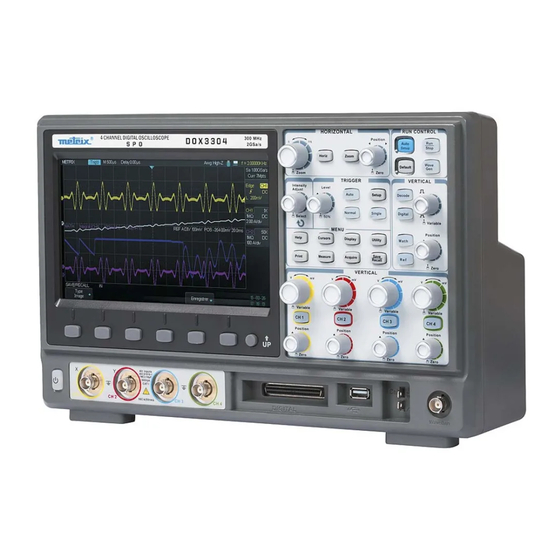
LCD TFT 8"
800 x 480
Interactive
Menu buttons
ON/OFF
Digital Storage Oscilloscope SPO
Analog Inputs
«Sensitive Phosphor Oscilloscopes»
DOX3104
4-voies - 100 MHz - 2 GSPS - 28MPts
WaveGenerator - Serial Bus Decode
DOX3304
4-voies - 300 MHz - 2 GSPS - 28MPts
WaveGenerator - Serial Bus Decode
User's Manual
Digital Inputs
Pôle Test et Mesure de CHAUVIN-ARNOUX
8-Channel Logic Analyzer
Control Front Panel
Arbitrary
Cal. 3V
USB
Generator
1kHz
host
Output
Advertisement
Table of Contents

Related Manuals for Metrix DOX3104


Summary of Contents for Metrix DOX3104
- Page 1 Digital Storage Oscilloscope SPO «Sensitive Phosphor Oscilloscopes» DOX3104 4-voies - 100 MHz - 2 GSPS - 28MPts WaveGenerator - Serial Bus Decode DOX3304 4-voies - 300 MHz - 2 GSPS - 28MPts WaveGenerator - Serial Bus Decode 8-Channel Logic Analyzer User’s Manual...
-
Page 2: Table Of Contents
Content Content General Instructions ................Introduction ..........Precautions and safety measures ............. Symbols on instrument ............ Guarantee, Repair, Servicing Instrument Description ................Front panel ................Rear panel ............. User display interface ............Menu and Control buttons ..........Front panel Inputs and Ouputs ............ - Page 3 Content ......................II - HORIZONTAL System ..............Horizontal menu ..............HORIZONTAL Pad ..............Horizontal Position ........... Time Base Coefficient S/div ..............Horizontal Zoom ....................... III - TRIGGER System ................Trigger Menu ................. Tigger Source ................Trigger Type .................. Edge ................. Pulse ................
- Page 4 Content Content (cont’d) ........................V - Display System ................... Display ............SPO : Color ON - Color Off ................X-Y Format ......................VI - Measurement System ............... Scale measurements ............Cursors measurement ......Manual Cursors ......Track Mode ............Automatic measurements ......
- Page 5 Content ..................... IX - Arbitrary Waveform Generator ..... Creating an arbitrary waveform with EasyWave ....Auto-Calibrating the arbitrary waveform generator ................X - DECODE option for Decoding Serial Bus ............... I2C serial bus .............. Setting I2C Trigger ..............Decoding I2C ............
-
Page 6: General Instructions
General Instructions You have just acquired a 4-channel SPO Digital oscilloscope: Introduction DOX3104, 4-channel, 100 MHz, 2 GSPS, 28Mpts, Arbitrary Waveform Generator, Serial Bus Decode or DOX3304, 4-channel, 300 MHz, 2 GSPS, 28 Mpts, Arbitrary Waveform Generator, Serial Bus Decode, 8-channel Logic Analyzer. -
Page 7: Symbols On Instrument
General Instructions General Instructions (cont’d) Warning: Risk of danger. Symbols on instrument Refer to the operating manual to find out the nature of the potential hazards and the action necessary to avoid such hazards. Selective sorting of waste for recycling electric and electronic materials. In accordance with the WEEE 2002/96/CE directive: must not be treated as household waste. -
Page 8: Instrument Description
Instrument Description Instrument Description Front Panel Description Description Universal Knob Trigger Control Horizontal Controls Common Functions Keys Auto Setup Vertical Controls « Default » Configuration Six menu buttons Run/Stop «Up » Menu button Generator set button « Wave On/Off button Gen »... -
Page 9: Rear Panel
Instrument Description Instrument Description (cont’d) Rear Panel 1. Handle To transport the oscilloscope turn the handle uprigth. 2. EXT TRIG External trig input BNC “EXT TRIG”. 3. « PASS/FAIL » output or trigger output « TRIG OUT » : The oscilloscope delivers either a square signal whose frequency is the number of waveforms acquired per second (Aux Output=Trig Out) or the number of “Fail”... -
Page 10: User Display Interface
Instrument Description Instrument Description (cont’d) User display interface Trigger status: Arm: The oscilloscope is acquiring pre-trigger data. All triggers are ignored in this state. Ready: All pre-trigger data has been acquired and the oscilloscope is ready to accept a trigger event. Trig’d: The oscilloscope has detected a trigger event and is acquiring the post-trigger data. -
Page 11: Menu And Control Buttons
Instrument Description Indicates the date and time Instrument Description (cont’d) Menu and Control buttons and knobs Horizontal Control Arbitrary Generator Advanced Trigger Control Functions Common Menu buttons Vertical Control Submenu buttons Channel Press the CH1 (or CH2 or CH3 or CH4) button to enable (ON) or disable (OFF) the channel and to open the CHi configuration menu. - Page 12 Instrument Description Default Press this button to reset the oscilloscope settings to the « Default » configuration Decode Press this button to enable and configure the serial bus « Decode » option Math Press this button to enable and configure the « MATH » function. Digital Press this button to enable and configure the 8 channel «...
-
Page 13: Front Panel Inputs And Ouputs
Instrument Description Instrument Description (cont’d) Input BNCs , Logic Logic Analyzer USB A AWG out Analyzer Probe On/Off Input BNCs Connector, USB host, Probe adjust Output, Arbitrary Waveform Generator Output BNC Channel input BNC : 4 BNCs connectors for input signals. CH1, CH2, CH3, CH4 Logic Analyzer 8-channel logic analyzer input connector... -
Page 14: Getting Started
Getting started Getting started Verification of To check the operation of the oscilloscope, perform the following steps: instrument operation Steps 1. Turn on the oscilloscope. Press the « Default » button of the « RUN CONTROL » pad to load the «... -
Page 15: Probe
Getting started Getting started (cont’d) Oscilloscope A guard around the probe body protects fingers from electric shocks. Probe Before performing a measurement : Plug the probe in the “BNC” input of the oscilloscope and then connect the alligator clip of the probe to the ground reference potential of the circuit under test. -
Page 16: Probe Compensation
Getting started Getting Started (cont’d) Probe Adjust Warning : The DOX3000 series have a switchable input impedance: 1MΩ - 50Ω. When using a « 1/10 » probe of 10MΩ input impedance (= 9MΩ for the probe + 1MΩ oscilloscope input) it is imperative to set the oscilloscope input impedance to 1MΩ. -
Page 17: Function Description
Functional Description Functional Description AUTO SETUP Auto Setup « Auto Setup » button on « RUN CONTROL” block DOX3000 digital oscilloscopes have an « Auto Setup » function that configures automatically the device to produce a display adapted to the signals at the channel inputs. -
Page 18: Default Configuration
Functional Description Functional Description AUTO SETUP (cont’d) Function Value « Auto setup » Sampling Mode unchanged function Display Format Display Type Vectors Input Coupling Bandwidth limit Unchanged V/div V/div adjust Coarse (séquence 1 2 5) Invert Signal unchanged Horizontal Position Centered S/div Trigger Type... -
Page 19: I - Vertical System
Functional Description Functional Description I - VERTICAL System Vertical knobs and buttons allow to display waveforms and to modify sensitivity and vertical position. CH1 CH2 CH3 CH4 « Volt/div » knobs CH1 CH2 CH3 CH4 buttons to open vertical menu and set channels “on”... -
Page 20: Channel Configuration
Functional Description Functional Description I - VERTICAL System (cont’d) Setting up: Press the CH1 (CH2, CH3 or CH4) button to open the corresponding channel CH1,CH2, menu. CH3, CH4 channels ● Pressing “CH1” → “Coupling”→ “AC”, Set to AC the CH1 input coupling: Selecting the channel Input The DC component of input signal is blocked. -
Page 21: Input Coupling
Functional Description Injecting a “<1ns” rise time “1MHz” square wave on channels CH1 and CH2 . The picture below shows a “1MHz” square wave displayed with the bandwidth limit "20M" on CH2 and with the “full” bandwidth on CH1: The measured rise time is 1.8ns on CH1 and 17.20ns on CH2, the presence of the «... -
Page 22: Vertical Sensitivity
Functional Description Functional Description I - VERTICAL System (cont’d) Adjusting vertical sensitivity V/div Vertical scale adjusting has « Coarse » and « Fine » mode, vertical sensitivity range is 2mV/div to 10V/div. For example, for CH1: ● Pressing “CH1”→ “Volts/Div”→ “Coarse” sets “V/div” adjust to “coarse” default value. -
Page 23: Probe Factor
Functional Description 4° Increase the frequency of the generator to obtain a « 6 divisions amplitude » signal on both channels, the frequency measured by the oscilloscope (21.6MHz in our example) is the CH2 cutoff frequency with the bandwidth limit to 20M. Probe In the CHi menu, select the probe «... -
Page 24: Input Impedance
Functional Description Functional Description I - VERTICAL System (cont’d) Inverting For example, on CH1: Waveforms ● Press “CH1”→ ″Page Suiv″ (″Next Page“) ″page 2/2” →“Invert”→“On”: We show below, the same positive square wave on CH1 with invert « On » and on CH2 with invert «... -
Page 25: Vertical Unit
Functional Description The rise time = 1.5ns and the amplitude = 286mV 2° CH1 input impedance « 1MΩ » : The rise time = 2.2ns and the amplitude = 576mV (twice that obtain with « 50Ω ») Conclusion : The « 50Ω » input impedance is best suited to observe fast rising edge waves provided by 50Ω... -
Page 26: Vertical Knobs
Functional Description Functional Description I - VERTICAL System (cont’d) 2. Vertical Knobs Vertical Position knobs 1. Use the vertical "Position" knobs to move traces up and down the screen. The vertical position variation range is : + /- 1V for vertical sensitivities from 2mV/div to 100mV/div +/- 10V for vertical sensitivities from 102mV/div to 1V/div +/- 100V for vertical sensitivities from 1.02V/div to 10V/div 2. -
Page 27: Storing And Displaying Reference Waveforms
Functional Description Option Value Description REF Menu Source CH1 CH2 Select the waveform to save CH3 CH4 Math REFA REFB Select the REF memory location. REFC REFD Save Save the waveform in the selected memory location REFA/REFB/ Recall and Display the selected REF. REFC/REFD Clear the displayed REF waveform. -
Page 28: Mathematical Funstions
Functional Description Functional Description I - VERTICAL System / MATH Functions Menu MATH The « MATH » menu displays the results of mathematicals operations: +, -, *, /, FFT, d/dt, ∫dt and √ on channels CH1, CH2, CH3, CH4 and REFA, REFB, REFC, REFD waveforms. -
Page 29: Fast Fourier Transform Fft
Functional Description Functional Description I - VERTICAL System / MATH Funtion (Cont’d) The “Fast Fourier Transform « FFT » process” mathematically converts à time « Fast Fourier domain signal into its components in the frequency domain. Transform » Two measurements are available on the FFT spectrum : Magnitude (in Vrms or dBVrms) and Frequency (in Hz). -
Page 30: Displaying The Fft Spectrum
Functional Description Functional Description I - VERTICAL System / MATH Function (cont’d) 2) Displaying the Press the « Math » button to display the MATH menu. Use the options to select: the Source channel, the Window, and the FFT Zoom Factor. You can display only FFT Spectrum one FFT spectrum at a time. -
Page 31: Selecting The Fft Window
Functional Description And using the “Y1” manual cursor we can determine the amplitude (Vrms) Y1=316mVrms ≈ (896mV/2)x0,707 = 316,7mVrms) 3) Selecting the The FFT window reduces spectral leakage in the FFT spectrum. The FFT assumes that the Y(t) waveform repeats indefinitely. With an integer number of FFT window cycles, the Y(t) waveform starts and ends at the same amplitude and there are no discontinuities in the signal shape. -
Page 32: Fft : Vertical And Horizontal Scales
Functional Description Functional Description I - VERTICAL System/ MATH Function (cont’d) FFT:Vertical and You can magnify and use cursors to take measurements on the FFT spectrum. Horizontal Scale, Vertical The oscilloscope includes an "FFT Zoom" option to magnify horizontally, press this button and Horizontal Position to select : "1X", "2X", "5X", or "10X". -
Page 33: Frequency
Functional Description Functional Description I - MATH Function (cont’d) Measure 1. Press the « Cursors » button frequency with 2. Press cursor “Mode” button and select “Manual”. « Xi » Vertical 3. Select "Xi" vertical cursor type Cursors 4. Press the "Source" button and select "MATH". 5. -
Page 34: Fft Of « Cal 3V 1Khz » Signal
Functional Description 1° Enter the « CAL 3V 1kHz » signal on CH4 with a 1/1 probe FFT of « Cal 3V 1kHz » 2° Channel CH4 coupling = DC 3° Select 1.4Mpts memory depth and a 500ms/div Time Base 4°... -
Page 35: Ii - Horizontal System
Functional Description Functional Description II - HORIZONTAL System The ″HORIZONTAL″ pad contains two buttons (Horiz and Zoom) and two knobs HORIZONTAL (S/div and Horizontal Position). Menu Horizontal Positon S/div knob knob Horiz and Zoom menu buttons HORIZONTAL « Horiz » button of the HORIZONTAL pad Menu Option Setting... -
Page 36: Horizontal Pad
Functional Description Functional Description II - HORIZONTAL System (cont’d) HORIZONTAL pad The “HORIZONTAL pad” knobs allow to adjust the Time Base coefficient « S/div » and the traces horizontal Position. The two buttons allow to open the HORIZONTAL menu (“Horiz”) and to activate the “Zoom”... -
Page 37: Horizontal Position
Functional Description Operation Steps To display in details a portion of the waveform: 1. Press the "Horiz" button to open the HORIZONTAL menu. 2. Turn the "S/div" knob to adjust the main timebase. 3. Press the « Zoom » button to activate the horizontal Zoom. 4. -
Page 38: Iii - Trigger System
Functional Description Functional Description III - Trigger System The DOX3000 oscilloscope series have a digital trigger system that has the TRIGGER Menu following advantages: Precise Trigger - Low « Jitter » - High Sensitivity Precise Trigger timing < 1ns - Configurable noise reject High stability with temperature A hardware counter allows to display the frequency of the trigger source signal in the top right of the screen... -
Page 39: Tigger Source
Functional Description "Single” button: Press the "Single" button to activate the SINGLE mode. In this mode only one acquisition is allowed at a time. Pre-trig/Post-trig/Trig-Delay: Datas before and after the trigger event . If the trigger symbol is at the center of the screen, the portion of the traces corresponding to the first 7 divisions represent the pre-trig and the 7 following divisions the post-trig. -
Page 40: Trigger Type
Functional Description Functional Description III - TRIGGER System (cont’d) Edge Option Settings Description Trigger Type Edge The rising or falling edge of the signal source is used to « Edge » trigger. CH1 CH2 CH3 CH4 Source Note : The trigger source is active even if the channel is off. -
Page 41: Pulse
Functional Description Functional Description III - TRIGGER System (cont’d) 2. «Pulse» Use the Pulse type to trigger on a particular “pulse width” with respect to the entire signal. Pulse Option Settings Description Trigger Type Pulse Select the trigger pulse type page 1 and width. - Page 42 Functional Description Functional Description III - TRIGGER System (cont’d) Pulse Trigger Option Settings Description page 2 Type Pulse Coupling Select the trigger coupling. LF Reject HF Reject Noise Reject enable Noise Reject Noise Reject disable Press this button to open the page 1/2 Next Page 2/2 Operation Steps 1.
-
Page 43: Video
Functional Description Functional Description III - TRIGGER System (cont’d) «VIDEO»Trigger To trigger on « Lines » or « Frames » of standard video signals. Video Trigger Option Settings Description Type Video To trig on video signals: NTSC, PAL/SECAM, HDTV and custom. Source CH1, CH2, CH3, CH4 Select the trigger source. -
Page 44: Slope
Functional Description Functional Description III - TRIGGER System (cont’d) Trigger on a positive or negative slope whose duration is specified. « Slope » « Slope » Trigger Option Settings Description page 1 Type Slope Trigger on a positive or negative slope of specific duration. - Page 45 Functional Description Functional Description III - TRIGGER System (cont’d) Slope Trigger Option Settings Description Type Slope page 2 Level Lower Select the level (L1 or L2) to adjust with the Upper trigger "Level" knob. You can adjust the two levels 'L1' & "L 2" that define the slope. Coupling DC - AC Select the trigger coupling...
-
Page 46: Window
Functional Description Functional Description III - TRIGGER System (cont’d) « Window » trigger When the « window » trigger type is enabled, the oscilloscope triggers when the signal exits, the window defined by the two levels L1 and L2, from the top or bottom level. -
Page 47: Interval
Functional Description Functional Description III - TRIGGER System (cont’d) Interval Option Settings Description Trigger In this mode the trigger event occur on the second Type edge, when the time interval between two Interval consecutive edges is : < or > or <> or >< to the set page 1 value. -
Page 48: Dropout
Functional Description Functional Description III - TRIGGER System (Cont’d) « DropOut » Option Settings Description trigger A trigger event occurs if the signal disappears for a time Type DropOut page 1 longer than the specified « DropOut » duration. Source CH1, CH2 Select the trigger source CH1 or CH2 or CH3 or CH4 CH3, CH4... -
Page 49: Runt
Functional Description Functional Description III - TRIGGER System (cont’d) « Runt » Option Settings Description Trigger Type Runt A trigger event occurs if the pulse (negative or positive) crosses the first level (L1) but not the second level (L2) page 1 of the window, before recrossing the (L1) level in a given time. -
Page 50: Pattern
Functional Description Functional Description III - TRIGGER System (cont’d) « Pattern » Option Settings Description Trigger Type Pattern Triggers when the «pattern» condition goes without the from false to true. « Digital » option We can also adjust the time duration of the pattern “true”... - Page 51 Functional Description « Pattern » with Option Settings Description « Digital » option Type Pattern Triggering when the «pattern» condition page 1/4 goes from false to true. We can also adjust the time duration of the pattern “true” condition. Note : Input coupling must be : DC. CH1 CH2 Select the Pattern inputs and the active level : Inputs CHi...
- Page 52 Functional Description « Pattern » with Option Settings Description « Digital » option Type Pattern Digital inputs : select the logic type to set page 2/4 automatically the threshold : TTL - CMOS - LVCMOS3.3 - LVCMOS2.5 or Custom D0 D1 Select the pattern inputs and the active level: Di Inputs D2 D3...
-
Page 53: I2C
Functional Description Functional Description III - TRIGGER System (cont’d) () Option Settings Description « Serial1-2 » Serial1 I2C is the default setting on Serial 1. Trigger Start - Stop - Restart - Condition No Ack Condition EEPROM Limit Range = , > , < Data1 0xXX Condition... -
Page 54: Serial 1-2
Functional Description Functional Description III - TRIGGER System (cont’d) () Trigger Option Settings Description « Serial 2 » Serial 2 SPI is the default setting on Serial 2 Trigger Setting Trigger Setting Trigger type MOSI MISO Data Length 4 to 96 ajustable Bit Roll 0 to 95 Bit Value... -
Page 55: Uart/Rs232
Functional Description Functional Description III - TRIGGER System (cont’d) Trigger Option Settings Description « Serial1-2 » Serial1 UART/RS232 Trigger on UART/RS232 serial bus. Trigger Setting Source Type RX TX Condition Start - Stop - Data - Parity error Configure Baud 600-1200-2400-4800-9600-19200-38400-57600- 115200-Custom Data Length... -
Page 56: Can
Functional Description Functional Description III - TRIGGER System (cont’d) Trigger Option Settings Description « Serial 1-2 » Serial 1 Trigger on CAN serial Bus Trigger Setting Start - Remote - ID - ID+DATA - Error TRIG SET Configure Baud 5kb/s-10kb/s-20kb/s-50kb/s-100kb/s-125kb/s-250kb/s- 500kb/s-800kb/s-1Mb/s-Custom 4-Channel SPO Digital Oscilloscopes... -
Page 57: Lin
Functional Description Functional Description III - TRIGGER System (cont’d) Trigger Option Settings Description « Serial1-2 » Serial1 Trigger on LIN serial Bus. Trigger Setting Condition Break - ID - ID+DATA - Data Error Configure Bit Rate 600-1200-2400-4800-9600-19200-Custom 4-Channel SPO Digital Oscilloscopes... -
Page 58: Trigger Coupling
Functional Description Functional Description III - TRIGGER System (cont’d) Use the appropriate coupling to the trigger source signal. Trigger COUPLING To select the trigger coupling, first press the "Setup" button to open the trigger menu and select the trigger type : "Edge", "Pulse", Video", "Slope", "Window", "Interval", "DropOut"... -
Page 59: Holdoff
Functional Description Functional Description III - TRIGGER System (cont’d) Triggering Inhibition time HOLDOFF Use the « Holdoff » to obtain a stable display in the case of complex signals such as pulse bursts. The “HoldOff” represents the time interval between the detection of a valid trigger event and the moment when the oscilloscope is ready to detect a new trigger event. - Page 60 Functional Description Holdoff = 355µs<392µs the oscilloscope displays two waveforms resulting from a double triggering (Blue and Red waveforms) Holdoff = 393µs > 392µs the oscilloscope display only the red waveform This holdoff value prevents the double triggering 4-Channel SPO Digital Oscilloscopes...
-
Page 61: Iv - Acquisition System
Functional Description Functional Description IV - ACQUISITION System Acquisition menu « ACQUIRE » When acquiring an analog signal, the oscilloscope converts it into digital format and displays a waveform. The acquisition mode defines how the signal is digitized. The time base setting multiplied by the number of horizontal divisions of the screen determines the duration of the recording in seconds (“S/div”... -
Page 62: Acquisition Configuration
Functional Description Functional Description IV - ACQUISITION System (cont‟d) « Acquire » Press the "Acquire" button to open the acquisition menu. Acquisition Option Settings Description Settings This mode is used for an accurate sampling and display Normal of most signals. Acquisition This mode is used to display noise and to reduce Peak Detect... -
Page 63: Acquisition Modes
Functional Description Functional Description IV - ACQUISITION System (cont‟d) Sampling Modes The oscilloscope has the following sampling modes: Normal - Peak Detect - Average - High Resolution Normal The oscilloscope samples the signal at regular intervals to build the digital waveform. -
Page 64: Average
Functional Description Functional Description IV - ACQUISITION System (cont‟d) In this mode, the oscilloscope performs “Multiple Waveforms” acquisitions, Average Mode average them and displays the resulting “1 Waveform”. Advantage Use this mode to reduce the random noise. A noisy sine wave acquire in « Normal » and « Average » (128) modes High Res mode High Res The High Res mode uses «... -
Page 65: Sequence
Functional Description Functional Description IV - ACQUISITION System (cont‟d) Sequence Mode In the Sequence mode, the recording memory is segmented. The oscilloscope captures and records a waveform (Frame) at each trigger event. When the acquisition sequence is completed, the oscilloscope displays the first 20 acquired waveform segments. In this mode, the “waveform capture speed”... - Page 66 Functional Description Functional Description IV - ACQUISITION System (cont‟d) Advantage This mode allows you to increase the maximum waveforms recording (in a segmented memory) frequency to 300000 Waveforms/s. It allows us to observe details that rarely occur, because the « blind time » (time without signal acquisitions) is minimized. Disadvantage The oscilloscope displays the acquired waveforms once the acquisition sequence is completed.
-
Page 67: Memory Depth Setting
Functional Description Functional Description IV - ACQUISITION System (cont‟d) Memory Depth Advantage A deep memory allows to record the signal evolution over a long period of time, and then analyze it in detail with a very fine elementary pitch. For example with a 28Mpoints memory depth we can record the evolution of a signal for 14ms with an elementary pitch of 0.5ns. -
Page 68: Time Base
Functional Description Functional Description IV - ACQUISITION System (cont‟d) Time Base The oscilloscope digitizes the waveform by sampling the input signal at a regular time interval. The Time Base coefficient and the Memory Depth set the sampling frequency. Use the "S/div" knob to set the “Time Base” coefficient. Open the «... - Page 69 Functional Description Functional Description IV - ACQUISITION System (cont‟d) Operation Steps To set sampling Press the “Acquire” button to open the ACQUIRE menu. Press the « Acquisition » button and use the “Universal” knob to select the acquisition mode : “Normal”, “Peak detect”, “High Res” or “Average”. To set the «...
-
Page 70: Sequence Mode
Functional Description Functional Description IV - ACQUISITION System (cont‟d) SEQUENCE Mode In the « Sequence » mode, the oscilloscope is ready to display waveforms, once the acquisitions are completed. In this mode, the maximum number of acquisitions per second can reach 300000. For each trigger event, the oscilloscope fills a segment of the recording memory and continues until the memory is completely filled. -
Page 71: Run/Stop Single Auto Normal
Functional Description Functional Description IV - ACQUISITION System (cont‟d) RUN/STOP SINGLE AUTO NORMAL Run/Stop Press the "Run/Stop" button to start (Run/Stop button is lit in yellow) the signal acquisition, press this button again to Stop (Run/Stop button is lit in red). -
Page 72: Display System
Functional Description Functional Description V - DISPLAY System Display Menu Press the "Display" button to open the DISPLAY menu. MENU pad Display Option Settings Description Type Vectors Two adjacent points (samples) are connected by page 1 a straight segment. Points Points (samples) are not connected together . - Page 73 Functional Description Functional Description V - DISPLAY (cont‟d) Option Settings Description «Display» Menu Display the grid and the axes. page 2 Display the axis. Grid Grid and axis are not displayed. Intensity Sets the trace intensity. Brightness Sets the Grid intensity. Transparence Set the transparence.
- Page 74 Functional Description Functional Description V - DYSPLAY System (cont‟d) Operation Steps 1. To set the display type 1) Press the "Display" button to open the DISPLAY menu. 2) Press the "Type" button and select "Vectors" or "Points". 2. To set the Color Press the "Color″...
-
Page 75: X-Y Format
Functional Description Functional Description V - DISPLAY System (cont‟d) X-Y Format The XY format is used to analyze the phase difference between signals using the Lissajous figures. In « XY » mode, channel CH1 (CH3) is the X axis and channel CH2 (CH4) the Y axis. - Page 76 Functional Description ● Channel CH1 (or CH3) X axis, the corresponding “V/div” and vertical Operation Steps “Position” knobs allows to adjust the horizontal scale and position. ● Channel CH2 (or CH4) Y axis, The corresponding “V/div” and vertical “Position” knobs allows to adjust the vertical scale and position. ●...
- Page 77 Functional Description Functional Description VI - MEASURE System The oscilloscope displays the waveform, that is to say the variation of the signal MEASUREMENTS amplitude (voltage or current) as a function of time. The oscilloscope displays : the vertical and horizontal scales and the automatic and cursors measurements values.
- Page 78 Functional Description Functional Description VI - MEASURE Sytem (cont‟d) When the « Manual Cursors » are active, the display shows two horizontal or vertical parallel cursors to measure voltage (Y cursors) or time (X cursors). Use the "Universal" knob to move the cursors. Select the appropriated reference source for cursors measurements.
- Page 79 Functional Description Functional Description VI - MEASURE Sytem (cont‟d) Operation 1. Press the "Cursors" button to open the CURSORS menu. Steps 2. Press the “Mode” button and select “Manual”. 3. Press the "Type" button and select : "X1" or "X2" or "X1-X2" or "Y1" or "Y2" or "Y1- Y2".
- Page 80 Functional Description The « Track » mode displays two cross cursors attached to the trace. With the “Universal” knob, you can only adjust the horizontal position of the selected cross cursor. The oscilloscope displays the ∆V and ∆T values. Operation 1.
-
Page 81: Automatic Measurements
Functional Description Functional Description VI - MEASURE Sytem (cont‟d) Automatic Press the "Measure" button to open the MEASURE menu : Measurements Menu Menu Pad Three types of automatic measurements : Voltage measurements Time measurements Delay measurements Of the 32 automatic measurements available, 23 of them (14 voltage and 9 time) can be displayed individually with or without their statistics. - Page 82 Functional Description Functional Description VI - MEASURE Sytem (cont‟d) Statistics Press the «Statistics» button to open the «Statistics» sub-menu: We can then view statistics of the displayed measurements, the oscilloscope displays the following values: Average, Min, Max, Standard Deviation and the Number of measurements. All Measures Option Description...
- Page 83 Functional Description Functional Description VI - MEASURE System (cont‟d) 1. Automatic Option Settings Description Voltage Source CH1 CH2 CH3 CH4 Select the reference channel for Measurements voltage measurements. Type Vmax, Vmin, Vpp, Vamp, Press the "Type" button and use Vtop, Vbase, Cycle Mean, the "Universal"...
- Page 84 Functional Description Functional Description VI - MEASURE System (cont‟d) Description Type of measure Description of the type of Waveform maximum peak voltage. Vmax measure Waveform minimum peak voltage. Vmin Absolute difference value between maximum and minimum peak voltage of the entire waveform Upper level most common voltage value of the waveform.
- Page 85 Functional Description Functional Description VI - MEASURE System (cont‟d) Operation Steps Voltage measurements To display a particular voltage measurement : 1. Press the "Measure" button to open the "MEASURE" menu. 2. Press the "Source″ button to select the channel source for measurements: "CH1", "CH2", "CH3", "CH4".
- Page 86 Functional Description Functional Description VI - MEASURE System (cont‟d) Operation Steps Time measurements To display a particular time measurement : 1. Press the "Measure" button to open the "MEASURE" menu 2. Press the "Source″ button to select the channel source for measurements: "CH1", "CH2", "CH3", "CH4".
-
Page 87: Vii - Save/Recall System
Functional Description Functional Description VII - SAVE/RECALL System Press the “Save/Recall” button to open the SAVE/RECALL menu. This menu Save/Recall allows to Save/Recall : Setups, Waveforms, Picture, .CSV files. 4 data types can be saved : - Setups - Waveforms - Pictures - .CSV files The «Setups»... -
Page 88: Save/Recall
Functional Description Functional Description VII - SAVE/RECALL System Pres the « Save/Recall » button to open the ”SAVE/RECALL” menu : 1. SAVE/RECALL Menu You can save « Setups » in internal or external memory You can save Waveforms, Pictures and .CSV files only in external memory 4-Channel SPO Digital Oscilloscopes... - Page 89 Functional Description Functional Description VII - SAVE/RECALL System (cont‟d) Saving « Setups » To save a «Setup» file in the oscilloscope internal memory : in Internal or 1° Press the « Save/Recall » button to open the SAVE/RECALL menu. External memory 2°...
- Page 90 Functional Description 9° The Setup file « dox3302s » is saved in the USB memory device as dox3302s.SET We can « recall » a setup file from an internal or an external memory. To Recall a Setup file To Recall a Setup To Recall a Setup file from the oscilloscope internal memory file from an internal 1°...
- Page 91 Functional Description Functional Description VII - SAVE/RECALL System (cont‟d) Rename We can Rename an existing Setup file 1° Press the « Save/Recall » button to open the SAVE/RECALL menu 2° Press the « Type » button and select « Setups » 3°...
-
Page 92: Save/Recall Waveforms
Functional Description Functional Description VII - SAVE/RECALL System (cont‟d) Waveforms are saved only in external memory, therefore before saving or 2. Save/Recall recalling a waveform plug the USB memory device in the “USB host” front Waveforms panel connector of the oscilloscope. You can save a «... - Page 93 Functional Description Press the « Save » or « Load » buttons to open the SAVE or RECALL sub- menus, both submenus have the same functionality : Option Settings Description Modify Files to modify files or directories Directory Press the “New” button to enter the file name using the “Universal”...
- Page 94 Functional Description Functional Description VII - SAVE/RECALL System (cont‟d) The oscilloscope can save a screen copy (« Picture ») in a external memory. The Save a Picture oscilloscope can’t recall a picture file (.BMP) . To save a screen copy (« Picture ») as a .BMP file Saving a screen copy «...
- Page 95 Functional Description Functional Description VII - SAVE/RECALL System (cont‟d) 2.2 Saving a To save a screen copy in an external memory : screen copy Open the SAVE/RECALL menu and select the Picture type, press the «Save» (Picture) button to open the Save submenu to save a screen copy .BMP. Option Settings Description...
- Page 96 Functional Description Functional Description VII - SAVE/RECALL System (cont‟d) Saving CSV files The CSV files must be saved in external memory. The CSV files can’t be opened in the oscilloscope. The CSV files can be opened in table software “EXCEL”. 1.
- Page 97 Functional Description Menu Save Type CSV Submenu « Save» « New » .CSV file 4-Channel SPO Digital Oscilloscopes...
- Page 98 Functional Description Functional Description VII - SAVE/RECALL System (cont‟d) Restoring the Press the « Default » button to restore the « Default Setup » : «Factory Settings» (Default Setup) Display obtained after restoring the « default setup »: Channel CH1 Sensitivity: 1V/div, Probe factor: 1X, Impedance: 1MΩ,...
- Page 99 Functional Description parameters of the restored waveform you must press the corresponding “CHi” button. 2° We can perform automatic or cursors measurements. 3° If we « Run » new acquisitions by pressing the « Run/Stop » button, the restored waveform is cleared and replaced with the new acquire waveform. Warning : The new acquisitions are done with the settings corresponding to the restored waveform.
- Page 100 Functional Description To refreshed the vertical parameters of the restored (CH3) waveform you must press a « CHi » button. If we « Run » new acquisitions by pressing the « Run/Stop » button, the restored waveform is cleared and replaced with the new acquire waveform.
-
Page 101: Utility Menu
Functional Description Functional Description VIII - UTILITY UTILITY Press the "Utility" button to open the UTILITY menu. MENU Pad Utility Menu Option Settings Description page 1/3 System Displays the hardware and software configurations Status of the oscilloscope. Do Self To start the self-calibration of the oscilloscope Allows to access the HISTORY of acquired History waveforms in SEQUENCE mode. - Page 102 Functional Description UTILITY do self Cal Press “Single” to begin When “Do self Call” ends “Press Run/Stop to Exit” UTILITY submenu System Status 4-Channel SPO Digital Oscilloscopes...
- Page 103 Functional Description Functional Description VIII - UTILITY (cont‟d) « Utility » Option Valeurs Instructions page 2/3 To open the Pass-Fail menu Pass/Fail To set the Input/Output interfaces Aux Output To enable the « Power Analyzer » option, when the option is installed.
- Page 104 Functional Description Submenu Pass/Fail page ½ Submenu Pass/Fail page 2/2 Submenu History Submenu Print Setup 4-Channel SPO Digital Oscilloscopes...
-
Page 105: Do Self Test
Functional Description Functional Description VIII - UTILITY (cont‟d) « Utility » Option Settings Description page 3/3 You can update the firmware or the oscilloscope Update configuration from an external USB memory device. Do Self Press this button to run the « Self Test » program : Screen, Test Keyboard and front panel LEDs. - Page 106 Functional Description Functional Description VIII - UTILITY (cont‟d) « Utility » Option Settings Description Screen Saver 1 min To set the time delay before switching to screen saver 5 min 10 min 30 min 1 hour 4-Channel SPO Digital Oscilloscopes...
- Page 107 Functional Description Functional Description VIII - UTILITY (cont‟d) « System Status » Press the « System Status » button to display the hardware and software configurations of the oscilloscope. System Status Option Description Number of “Power on” Displays the number of “power-on” of the device. (StartupTimes) Software Version Displays the firmware version.
- Page 108 Functional Description Functional Description VIII - UTILITY (cont‟d) « Print Setup » Set the « USB device » interface to « Printer » (Utility submenu « I/O ») and connect a ″Pict Bridge″ printer to the “USB Device” connector of the rear panel of the oscilloscope.
- Page 109 Functional Description Functional Description VIII - UTILITY (cont‟d) Print To Setup the USB « Pictbridge » printer interface. Setup Note : 1. The printer will modify your selection for best fit. 2. If your selection is not supported by the printer, the oscilloscope will use the default settings.
- Page 110 Functional Description Functional Description VIII - UTILITY (cont‟d) Print a screen copy Operation Steps 1. To connect the oscilloscope to a "PictBridge" compatible printer . 1) Plug the USB cable in the "USB Device" connector of the oscilloscope. 2) Plug the other end of the USB cable in the printer ″USB Pictbridge″ connector.
-
Page 111: Screen Test
Functional Description Functional Description VIII - UTILITY (cont‟d) SELF CAL « Do Self Cal » The « Self Calibration » procedure optimizes the channel (CH1 CH2 CH3 CH4) accuracy. You can run this procedure at any time. If the ambient temperature changes by more than 5°... -
Page 112: Led Test
Functional Description Functional Description VIII - UTILITY (cont‟d) «Keyboard Select " Keyboard Test" to enter the key test interface. The rectangle shapes Test» represent the front panel keys and the circle shapes the knobs : The 14 circles with an arrow on both sides represent the front panel knobs. For each knob can be tested : the direction of rotation (clockwise or counterclockwise) and the integrated switch. -
Page 113: Firmware Update
Functional Description Functional Description VIII - UTILITY (cont‟d) «Firmware Update the « Firmware » from a USB memory device. Update» The embedded software of the oscilloscope can be updated directly from a USB memory device. Operation 1. Plug the USB memory device with the new « firmware » version in the USB host Steps connector of the oscilloscope front panel and wait for the USB is displayed on the top... - Page 114 Functional Description Pass/Fail Option Settings Description Menu Enable the Pass/Fail test Enable Test page 1 Disable the Pass/Fail test CH1 CH2 Select the channel Source for pass Pass/Fail test. Source CH3 CH4 Operation Press to run the Pass/Fail test. Press to stop the Pass/Fail test. Enable the display of the number of tests that Pass or Msg Display Fail.
-
Page 115: Pass/Fail
Functional Description Functional Description VIII - UTILITY (cont‟d) Option Settings Description Pass/Fail The Pass/Fail test stop when real-time signal is menu Fail to Stop outside the mask. The Pass/Fail don’t stop on « Fail ». page 2 Sound On Output Sound Off Next Page Page 2/2... - Page 116 Functional Description X Mask set Y Mask set Create Mask To save the created Mask in the external memory select the External Location: Plug the USB device, press the « Save » button and wait for the oscilloscope displays the contents of the USB memory device : Press the «...
- Page 117 Functional Description Press the « Enter » button to save the mask file in the USB memory device, file « dox3304m.RGU » : The “Load” function allows to recall a saved Mask file (.RGU) 4-Channel SPO Digital Oscilloscopes...
- Page 118 Functional Description Functional Description VIII - UTILITY (cont‟d) Option Valeurs Instruction Perform On : Enable the « Pass/Fail » test once the Mask was Pass/Fail test Enable Test created Msg Display On : Enable the display of the Pass/Fail test results run the Pass/Fail test with the active Operation mask...
-
Page 119: History
Functional Description Functional Description VIII - UTILITY (cont‟d) « History » The « History » function allows to record and display a history of the last waveforms corresponding to the channels: CH1 CH2 CH3 CH4. In « RUN » the oscilloscope continuously records the signals present at the inputs of the channels : CH1 CH2 CH3 CH4, in the form of a sequence of memory segments «... - Page 120 Functional Description Example : A Fail test using the Pass/Fail function Option Settings Description History of the latest recorded frames. When the history View is « On » the acquisition Mode « History » automatically stops. This function allows to view the «...
- Page 121 Functional Description 1. Press the «Utility» button to open the “UTILITY” menu. Operation Steps 2. Press the "Next Page” button to open page 2/2. 3. Press the “History” button to open the ″HISTORY" submenu. 4. Press the “View Off” button to set the “View On”, the acquisitions are stopped to allow to view the “History”.
- Page 122 Functional Description Functional Description VIII - UTILITY (cont‟d) « Options » The « Options » submenu allows to manage the oscilloscope options: DECODE - ARBITRARY WAVEFORM GENERATOR - MSO LOGIC ANALYZER - POWER ANALYZER For each option the oscilloscope indicates whether it is installed or not and the type of license.
-
Page 123: « Options
Functional Description Functional Description VIII - UTILITY (cont‟d) Option Description The « Options » submenu allows to manage the « Options » Options oscilloscope options 4 options types are available : The are 3 software options: (DECODE - WAVE GENERATOR integrated) - PAS (contact us) The «... -
Page 124: Date/Time
Functional Description Functional Description VIII - UTILITY (cont‟d) « Date/Time » The oscilloscope display the time and date in the bottom right of the submenu screen. To set the time and date open the « Date/Time » submenu. Option Settings Description «... - Page 125 Functional Description Functional Description VIII - UTILITY (cont‟d) «I/O» The oscilloscope has rear panel interfaces « USB Device » and « Ethernet ». Open the “I/O” submenu ( page 1/3 of UTILITY menu) to set these interfaces : The « I/O » submenu allows to set the interfaces « USB Device » and « Ethernet » and also the Aux Output.
-
Page 126: Arbitrary Waveform Generator
Functional Description IX - « Arbitrary Waveform Generator » (AWG) option The DOX3000 oscilloscope series come with an Arbitrary Waveform Generators (AWG) that can generate 10 types of pre-defined waveforms (Sine, Square, Ramp, Pulse, DC, Noise, Cardiac, Gauss Pulse, Exponential Rise and Exponential Fall) and 4 arbitrary user defined waveforms (Arb 1, Arb 2, Arb 3, Arb 4). - Page 127 Functional Description IX - « Arbitrary Waveform Generator » (AWG) option (cont‟d) Create an arbitrary waveform with the « EasyWave » software and load it into the l‟oscilloscope AWG (Arbitrary Waveform Generator) 1° Press the « Wave Gen » button to open the WAVEFORM generator menu 2°...
- Page 128 Functional Description IX - « Arbitrary Waveform Generator » (AWG) option (cont‟d) 6° To verify that the waveform WAVE1 is saved in the location Arb 2, we use the « Read Wave » function and select on the « Wave list » the WAVE1 waveform: Then click the «...
-
Page 129: Auto-Calibrating The Arbitrary Waveform Generator
Functional Description IX - « Arbitrary Waveform Generator » (AWG) option (cont‟d) Automatic Calibration of the « Arbitrary Waveform Generator» If the ambient temperature varies by more than 5°C and the instrument was left « On » for more than 30 minutes you can start an automatic calibration of the generator output. -
Page 130: Decode Option For Decoding Serial Bus
Functional Description X - DECODE Option Serial Bus decoder The DOX3000 oscilloscope series come with serial bus Trigger and Decode option for : I2C - SPI - UART/RS232 - CAN - LIN I2C serial bus To analyse an I2C serial bus, we need to connect to the inputs of the oscilloscope the two I2C signals «... -
Page 131: Setting I2C Trigger
Functional Description X - DECODE I2C Serial Bus Decode (cont‟d) Trigger conditions on an I2C bus can be : A « Start/Stop » condition, a « Restart », a missing «Acknowledge», an EEPROM data read, a « Read/Write » frame with a specific device address and data value or a “Data Length”. Setting the I2C bus trigger 1°... - Page 132 Functional Description X - DECODE I2C Serial Bus Decode (cont‟d) EEPROM Data Read : The trigger looks for an « EEPROM control byte » value « 1010xxx » on the SDA line, followed by a « Read bit » and a SCL « Ack bit ». It then looks for the occurrence of the programmed “Data1”...
- Page 133 Functional Description X - DECODE I2C Serial Bus Decode (cont‟d) The 26th clock edge front trigger occurs for the following frame format : (Start :Address byte 1 :Write :Address byte 2 : Ack : Data) Data2 set to « 0xXX » The 34th clock edge trigger occurs for the following frame format : (Start :Address byte 1 :Write :Address byte 2 : Ack : Data: Ack: Data) Data2 must have a value other than «...
-
Page 134: Decoding I2C
Functional Description X - DECODE I2C Serial Bus Decode (cont‟d) Note : If you have selected a 3 bytes trigger, press the « Data2 » button and use the Universal knob to set the 8-bit value. 6° If you have selected the « Data Length » condition : Press the «... -
Page 135: Reading I2C Decoding
Functional Description X - DECODE I2C Serial Bus Decode (cont‟d) Interpreting I2C Decode line 1° The transition lines indicate an active bus (inside a packet/frame) 2° Mid-level blue lines indicate an idle bus 3° Decoded hexadecimal data: Address values appear at the start of a frame Write addresses are displayed in «... -
Page 136: Spi Serial Bus
Functional Description X - DECODE SPI Serial Bus Decode SPI Serial Bus Setting up the oscilloscope to capture SPI bus signals To analyse the SPI bus (Serial Peripheral Interface), we need to connect the inputs of the oscilloscope to the following SPI signals : Clock - MOSI data - MISO data - Framing And to set for each signal the logic threshold that defines the «... - Page 137 Functional Description X - DECODE SPI Serial Bus Decode (cont‟d) 8° Press the « UP » button to return to the SPI “SIGNAL” submenu 9° Press the « MOSI » button to open the « MOSI » submenu : a) Press the « MOSI » button and use the « Universal » knob to assign a channel to the SPI “MOSI”...
-
Page 138: Setting Spi Trigger
Functional Description X - DECODE SPI Serial Bus Decode (cont‟d) Setting the SPI Trigger Setting up the oscilloscope to capture SPI signals, and to trigger on a « Pattern » that occurs at the start of a frame. The serial data string length can be set from 4 to 96 bits. 1°... -
Page 139: Decoding Spi
Functional Description X - DECODE SPI Serial Bus Decode (cont‟d) SPI Serial Bus Decode Setting the SPI Serial Bus Decode : 1° Press the front panel « Decode » button to open the DECODE menu and select Decode SPI 2° Press the « Data Length » button and use the « Universal » knob to set the number of bits of the SPI decode datas 3°... -
Page 140: Reading Spi Decoding
Functional Description X - DECODE SPI Serial Bus Decode (cont‟d) Interpreting SPI Decode Transition lines indicate an active bus Mid-level blue lines indicate an iddle bus The number of clocks in a frame are displayed in ligth-blue above the frame on the right Decoded hexadecimel values are displayed in «... -
Page 141: Uart/Rs232 Serial Bus
Functional Description X - DECODE UART/RS232 Serial Bus Decode Setting up the oscilloscope to capture UART/RS232 signals 1° Press the front panel « Decode » button to open the « DECODE » menu. 2° Press the « Serial » button and select “Serial 1” or “Serial 2” 3°... -
Page 142: Setting Uart/Rs232 Trigger
Functional Description X - DECODE UART/RS232 Serial Bus Decode (cont‟d) Setting up the UART/RS232 Trigger To trigger on a UART (Universal Asynchronous Receiver/Transmitter) signal, connect the oscilloscope channels to the « RX » and « TX » lines and set up a trigger condition. RS232 (Recommended Standard 232) is one example of UART protocole. - Page 143 Functional Description X - DECODE UART/RS232 Serial Bus Decode (cont‟d) 4-Channel SPO Digital Oscilloscopes...
-
Page 144: Decoding Uart/Rs232
Functional Description X - DECODE UART/RS232 Serial Bus Decode (cont‟d) Setting the UART/RS232 serial bus Decode 1° Press the front panel « Decode » button to open the “DECODE” menu. 2° Press the « Display » button to set the display of the decode line « On » 3°... -
Page 145: Reading Uart/Rs232 Decoding
Functional Description X - DECODE UART/RS232 Serial Bus Decode (cont‟d) Interpreting the UART/RS232 Decode The transition lines indicate an active bus (inside a packet/frame) The mid-level blue lines indicate an iddle bus The mid-level red lines indicate that the idle level is wrong The decoded data are displayed in white The decoded text is truncated at the end of the associated frame when the space between the frame boundaries is insufficient... -
Page 146: Can Serial Bus
Functional Description X - DECODE CAN Serial Bus Decode Setting up the oscilloscope to capture the CAN bus signals To capture and analyse the CAN bus connect the CAN-H and CAN-L bus signals to the oscilloscope inputs and open the CAN bus “SIGNAL” and “Configure” submenus to set the : decode Source, Threshold, Baud rate. - Page 147 Functional Description X - DECODE CAN Serial Bus Decode (cont‟d) Triggering on ID 0x0105 Triggering on ID 0x0108 4-Channel SPO Digital Oscilloscopes...
- Page 148 Functional Description X - DECODE CAN Serial Bus Decode (cont‟d) The oscilloscope displays the following CAN signals : CAN_H on CH1, yellow trace CAN_L on CH2, red trace CAN_H-CAN_L on CH3, blue trace Note : We use a MX9030 (1/20) differential probe to capture the CAN_H-CAN_L Acquisition «...
- Page 149 Functional Description X - DECODE CAN Serial Bus Decode (cont‟d) Example : Measuring the amplitude of CAN HS with cursors . Amplitude of CAN_H HS signal: Amplitude of CAN_L HS signal: Automatic measurements : amplitude, rise and fall times : Expanding the horizontal scale we can display the following automatic measurements on CAN_H and CAN_L HS signals (CAN High Speed ): amplitude, rise and fall times: We notice that the amplitude ΔV is approximately 1V and the rise time of CAN_H and the fall time...
- Page 150 Functional Description X - DECODE CAN Serial Bus Decode (cont‟d) In our example, the measured amplitude of the CAN_H and CAN_L signals is 1.12V, close to the 1V nominal value of the “CAN High Speed”: CAN High Speed Nominal bus levels CAN HS nominal values CAN_H HS varies from 2.5V to 3.5V ...
-
Page 151: Setting Can Trigger
Functional Description X - DECODE CAN Serial Bus Decode (cont‟d) Setting the CAN Trigger 1° Press the front panel « Setup » button to open the “TRIGGER” menu 2° Press the « Type » button and use the « Universal » knob to select Serial 1 or Serial 2 3°... - Page 152 Functional Description X - DECODE CAN Serial Bus Decode (cont‟d) Triggering on a bus « CAN Low Speed » 125kb/s on the IDentifier 0x03b6 : We stop the acquisition and expand the horizontal scale to view in detail the « CAN Low Speed » (125kb/s) data flow, we use the cursors to determine the bit width : The «...
- Page 153 Functional Description X - DECODE CAN Serial Bus Decode (cont‟d) Set the List display « Off » : We measure : ΔT=X1-X2=8µs to 1/ΔT=125kb/s Measuring the amplitude of the CAN LS signals Amplitude of the CAN_H LS (CAN Low Speed) : The «...
- Page 154 Functional Description X - DECODE CAN Serial Bus Decode (cont‟d) Amplitude the CAN_L LS (125kb/s) signal : The « CAN_L LS » signal varies from 1V to 5V and its amplitude is : ΔV=Y2-Y1=4.06V Automatic measurement of the amplitude and the rise time of the CAN LS signals In our example of «...
- Page 155 Functional Description X - DECODE CAN Serial Bus Decode (cont‟d) Setting the CAN Bus DECODE 1° Press the front panel « Decode » button to open the “DECODE” menu 2° Press the « Display » button to set the display of the decoded line « On » 3°...
- Page 156 Functional Description X - DECODE CAN Serial Bus Decode (cont‟d) Interpreting the CAN Decode CAN Decode line The hex data bytes are displayed in white The hex CRC (Cyclic Redundancy Check) are displayed in blue when valid, or in red to indicate that the oscilloscope calculated CRC is different from the incoming CRC data stream.
-
Page 157: Decoding Can
Functional Description X - DECODE LIN Serial Bus Decode Setting up the oscilloscope to capture the LIN bus signals To capture the LIN (Local Interconnect Network) signal : Connect the LIN signal to the oscilloscope input Assign a channel to the LIN signal Set the threshold, the baud rate, the «... -
Page 158: Reading Can Decoding
Functional Description X - DECODE LIN Serial Bus Decode (cont‟d) Setting the LIN Trigger The LIN trigger allows to trigger on the rising edge of the « Sync Break » signal (at the start of the message frame), the frame identifier « ID » or the « ID+Data ». 1°... -
Page 159: Decoding Lin
Functional Description X - DECODE LIN Serial Bus Decode (cont‟d) Setting the LIN Serial Bus Decode 1° Press the front panel « Decode » button to open the DECODE menu 2° Press the « Display » button to set the decode line display « On » 3°... -
Page 160: Reading Lin Decoding
Functional Description X - DECODE LIN Serial Bus Decode (cont‟d) Interpreting the LIN decode line The transition lines indicate an active bus The mid-level blue lines indicate an Idle bus The identifier ID (hexadecimal) and the parity bit (if enabled) are in yellow or in red if a parity error is detected. - Page 161 Functional Description XI - Logic Analyzer « Digital » option (Contact us) The DOX-MSO3LA option (including a « Digital Analysis » software and an eigth-channel digital probe) transforms the DOX3000 into a Mixed Signal Oscilloscope (MSO) with “4 analog” and “8 digital” inputs. To start up the «...
- Page 162 Functional Description XI - Logic Analyzer « Digital » option (cont‟d) Press the « Channel High » button to select the display type, to vertically expand (High) or compress (Low) the 8 digital channels display. Press the « Channel Control» button and use the Universal knob to select the digital channel Press the «...
- Page 163 Functional Description XI - Logic Analyzer « Digital » option (cont‟d) With Display « On » : Use the « Position » knob to select a digital channel (red) and use the “Variable” knob to position the channel vertically. With Bus 1 (Binary) and Bus 2 (Hexadecimal) “On”: The oscilloscope displays simultaneously the 8 bit data bus value in “Binary”...
- Page 164 Functional Description XI - Logic Analyzer « Digital » option (cont‟d) The DOX3304 will allow us to make: 1° Cursor measurements (Voltage, Time) on all channels CH1 CH2 CH3 CH4 2° Automatic measurements on all analog channels CH1 - CH2 - CH3 - CH4 and on the 8 digital channels D0 to D7 : 4-Channel SPO Digital Oscilloscopes...
- Page 165 Functional Description XI - Logic Analyzer « Digital » option (cont‟d) The DOX3304 will display statistics on the active measurements (our example 5 active measurements on: D0, CH1 and CH4) : The DOX3304 also displays all « Time » and « Voltage » measurements on a channel CHi : 4-Channel SPO Digital Oscilloscopes...
- Page 166 Functional Description XI - Logic Analyzer « Digital » option (cont‟d) The DOX3304 allows to trigger on a « Pattern » that includes the analog channels (CH1 to CH4) and the digital channels (D0 to D7). In our example we set the following “AND” pattern : CH1 High (>900mV), CH2=CH3= X (don‟t care), CH4 High (>1V) and D0=Low D1=D2=High and D3=D4=D5=D6=D7= X (don‟t care).
-
Page 167: Power Analysis Option
Functional Description XII - « Power Analysis » Option (Contact us) The PAS (Power Analysis Sotfware) option is a tool for analysing the reliability and efficiency of Switching Power Supply. The « PAS » option allows characterization of : The Power Factor, the True Power, the Apparent Power, the Current Harmonics, the Switching Loss, the dI/dt and dV/dt Slew Rate, the Output Ripple, the Transient Response, the Efficiency Analysis, the Inrush Current etc... - Page 168 Functional Description XII - « Power Analysis » Option (cont‟d) Ex 2 Inrush current : Ex 3 Output Ripple (Input coupling DC) : 4-Channel SPO Digital Oscilloscopes...
- Page 169 Functional Description XII - « Power Analysis » option (cont‟d) Ex 4 Output Ripple (input coupling AC) : Ex 5 Switching Analysis: 4-Channel SPO Digital Oscilloscopes...
- Page 170 Functional Description XII - « Power Analysis » option (cont‟d) Ex 6 Slew Rate Analysis : Ex 7 Power Quality Analysis : 4-Channel SPO Digital Oscilloscopes...
- Page 171 Functional Description XII - « Power Analysis » option (cont‟d) Ex 8 Turn On Analysis : Ex 9 Turn Off Analysis : 4-Channel SPO Digital Oscilloscopes...
-
Page 172: Remote Control
Functional Description XIII - Remote Control of the Oscilloscope There are two methods to remotely control the oscilloscope: Remote Control using SCPI commands or using the specialized PC software « EasyScopeX » User can control the oscilloscope by programming through standard SCPI User-defined (Standard Commands for Programmable Instruments) commands. - Page 173 Functional Description XIII - Remote Control (cont‟d) 4-Channel SPO Digital Oscilloscopes...
- Page 174 Functional Description Connecting Open « EasyScopeX » software, click "Add Device" to start the search, the following dialog box appears: Devices Click the communication interface to use USBTMC (USB) or VXI11 (Ethernet). If the instrument is connected through USBTMC interface, select the instrument to open and click the «...
- Page 175 Functional Description If the active communication interface is VXI11, the following window appears: Enter the oscilloscope IP address (example 14.3.212.25) and click OK to remotely control the oscilloscope through « Ethernet ». Check The informations about the instrument « added » are displayed. See the examples below. The device “Serial Number”...
- Page 176 Functional Description Click "Send Command" button and enter (keyboard) the SCPI command : « *IDN? », Testing the communication press the « Enter » button to send the command. The « EasyScopeX » software sends interface the command to the oscilloscope, accepts the instrument datas and displays the instrument identification: ...
- Page 177 Functional Description Screen To perform a screen capture (displayed waveforms) Capture Scope To Control the oscilloscope through a virtual panel Configuration Virtual Panel By activating the virtual panel it is possible to remotely control the oscilloscope by acting on the softkeys and virtual knobs of the « Virtual Panel ». The “virtual screen” will react interactively to the actions on the “Virtual Panel”: For more details, please consult the «...
-
Page 178: Messages
Messages Messages / Help « Help » The oscilloscope has an embedded help function that supplies multi-language Help information ( English , French, German). To access help: Press the front panel "Help" button to activate the help, then press every button to display the corresponding help information. -
Page 179: Messages
Messages Messages (cont‟d) Messages Trig level at limit! : Indicates that the adjustable trigger level is at its limit. Horizon position at limit! : Indicates that the adjustable horizontal position is at its limit. Volts/Div at limit! : Indicates that the vertical scale “V/div” has reached the minimum “2mV/div”... -
Page 180: Diagnostic
(“On/Off” button lighting is fixed On) . - After the inspections above, restart the oscilloscope. - If the oscilloscope is still not usable after the checking, contact METRIX division CHAUVIN-ARNOUX (support area). 2. If the oscilloscope does not display any waveform with signals on input channels: (1) Check the input probe. -
Page 181: Technical Specifications
You must perform the « Do Self Cal » operation through the “Utility” Technical Specifications menu, if the operating temperature changes by more than 5°C. The oscilloscope must be within the calibration interval. All specifications are guaranteed unless note "typical" DOX3104 DOX3304 Inputs Channels... - Page 182 Characteristics Technical Specifications (cont‟d) Horizontal and DOX3104 DOX3304 Sampling system Dual Channel [CH1 CH3] or [CH2 CH4] : Dual Channel [CH1 CH3] or [CH2 CH4]: Real time sampling 2GSa/s 2GSa/s frequency 3 or 4 Channel : 1GSa/ 3 or 4 Channel: 1GSa/s...
- Page 183 Characteristics Polarity : +wid, -wid Limit : <, >, < >, > < « Pulse Trigger » Source : CH1 CH2 CH3 CH4 Adjustement Range: 2ns to 4,2s Resolution : 1ns Window Type : Absolute, Relative « Window Trigger» Source : CH1 CH2 CH3 CH4 Supported Standards : PAL/SECAM, NTSC, 720p/50, 720p/60, 1080p/50, 1080p/60, 1080i/50, 1080i/60, Custom «...
-
Page 184: Serial Decode
Characteristics “Serial Decode” Signal : SCL, SDA Bus I2C Address: 7bits, 10bits List : 1 to 7 lines Signal : CLK, MISO, MOSI, CS Slope select : Rising, Falling Idle Level : Low, High SPI bus Ordre des Bits : MSB, LSB Data Length : 4 to 96bits Liste : 1 to 7 lines Signal : RX, TX... - Page 185 Characteristics Waveform Arbitrary Generator Channels Maximum Frequency 25MHz Sampling Frequency 125Msa/s Number of points 16kpts Frequency Resolution 1µHz Vertical Resolution 14 bits 2mVpp to 3Vpp (50Ω) Amplitude Range 4mVpp to 6Vpp (High-z) Signal Sinusoidal Frequency 1µHz to 25MHz Precision (100kHz) ±...
- Page 186 Characteristics Technical Specifications (cont‟d) Display System LCD screen 8 inch TFT Color LCD (203,2 mm diagonal ) Resolution 800 pixels (horizontal) x 480 pixels (vertical) Colors 24 bit Display Contrast 500:1 (typical) Backligth Intensity 300nit (typical) Waveform display 8 x 14 div. Display Modes Points, Vectors Persistence...
- Page 187 "RoHS" European Directives. Mechanical Length 352 mm Dimensions Width 112 mm Height 224 mm Weigth 3,6 kg DOX3104 & DOX3304 models ABS VO (auto extinguishing) Materials Sealing IP20 Packaging Dimensions 430 x 240 x 365 mm Parts Accessories ...
- Page 188 Characteristics Appendix : Default Setup Menu or system Default setup T/div 1µs/div Horizontal Delay Zoom Format Y(t) Channel On/Off Vertical V/div 1V/div Vertical Position Input Coupling Full BW Limit V/div adjust Coarse 1 2 5 Probe Factor 1MΩ Input Impedance Vertical Unit Invert Acquisition mode...
-
Page 189: System Setup
Characteristics USB Device USBTMC Aux Output Trig Out Sound Sound Pass/Fail Enable Test Source Operate Mes Display X Mask Y Mask Location Internal Fail to Stop Output System Setup Quick-Cal Screen Saver 30mn Operate MATH Source A Source B Invert V/div 1V/div Vertical Position... - Page 190 Characteristics V/div 1V/div Vertical Position Source Window Hanning FFT Zoom Vertical Scale 20dBVrms Display Split Horizontal Scale 100MHz d/dt (dy/dx) Source Vertical Scale (1MV/s)/div = (1V/µs)/div Vertical position 0.2div ∫dt Source offset Vertical Scale 1µVs/div Vertical position √ Source Vertical Scale 1V½div Vertical position Source...
- Page 191 Characteristics Threshold 1,6V Edge Select Rising MISO Threshold 1,6V MOSI Threshold 1,6V CS Type Idle Level Bit Order Data Length UART/RS232 Threshold 1,6V Threshold 1,6V Baud 9600 Parity Check None Stop Bit Idle Level CAN-H Threshold 1,6V CAN-L Threshold 1,6V Baud 100kb/s Decode Source...
- Page 192 Characteristics Amplitude 4Vpp Offset 0Vdc Duty Cycle Ramp Frequency 1kHz Amplitude 4Vpp Offset 0Vdc Symmetry Pulse Frequency 1kHz Amplitude 4Vpp Offset 0Vdc Width 200µs Offset 0mVdc Noise St dev 300mV Mean Cardiac Frequency 1kHz Amplitude 4Vpp Offset 0Vdc Gauss Pulse Frequency 1kHz Amplitude...
- Page 193 07 - 2015 X04249A02 - Ed. 01 DEUTSCHLAND - Chauvin Arnoux GmbH SCHWEIZ - Chauvin Arnoux AG Straßburger Str. 34 - 77694 Kehl / Rhein Moosacherstrasse 15 - 8804 AU / ZH Tel: (07851) 99 26-0 - Fax: (07851) 99 26-60 Tel: 044 727 75 55 - Fax: 044 727 75 56 中国...
Need help?
Do you have a question about the DOX3104 and is the answer not in the manual?
Questions and answers