Table of Contents
Advertisement
Quick Links
D
i
g
D
i
g
D
i
g
T
w
o
-
c
h
a
n
T
w
o
-
c
h
a
n
T
w
o
-
c
h
a
n
n
T
w
o
-
c
h
a
n
n
Test et Mesure CHAUVIN-ARNOUX
6, avenue du Pré de Challes
F - 74940 ANNECY-LE-VIEUX
Tel. +33 (0)4.50.64.22.22
Fax +33 (0)4.50.64.22.00
i
t
a
l
O
s
c
i
t
a
l
O
s
i
t
a
l
O
s
325 5 5 5 2 2 2 2 e-C
32
32
32
n
e
l
,
6
0
M
H
z
n
e
l
,
6
0
M
H
S
S
3352e- - - - C
3352
3352
3352
e
l
,
1
0
0
M
H
z
e
l
,
1
0
0
M
H
S
S
O
p
e
r
a
t
i
n
g
I
n
s
t
r
u
O
p
e
r
a
t
i
n
g
I
n
s
t
r
u
O
p
e
r
a
t
i
n
g
I
n
s
t
r
i
l
l
o
s
c
o
c
i
l
l
o
s
c
o
c
i
l
l
o
s
c
o
,
E
t
h
e
r
n
e
t
z
,
E
t
h
e
r
n
e
t
m
a
r
t
P
e
r
s
i
m
a
r
t
P
e
r
s
,
E
t
h
e
r
n
e
t
z
,
E
t
h
e
r
n
e
t
m
a
r
t
P
e
r
s
i
m
a
r
t
P
e
r
s
c
t
i
o
n
s
c
t
i
o
n
s
u
c
t
i
o
n
s
GB - Maidenhead SL6 8BR
X03043A00 - Ed. 02 - 06/10
p
e
s
p
e
s
p
e
s
,
C
o
l
o
r
,
,
C
o
l
o
r
,
s
t
e
n
c
e
i
s
t
e
n
c
e
,
C
o
l
o
r
,
,
C
o
l
o
r
,
s
t
e
n
c
e
i
s
t
e
n
c
e
CA UK Ltd.
Waldeck House
Waldeck Road
Advertisement
Table of Contents

Related Manuals for Metrix MTX 3252e-C


Summary of Contents for Metrix MTX 3252e-C
- Page 1 325 5 5 5 2 2 2 2 e-C 3352e- - - - C 3352 3352 3352 CA UK Ltd. Test et Mesure CHAUVIN-ARNOUX Waldeck House 6, avenue du Pré de Challes Waldeck Road F - 74940 ANNECY-LE-VIEUX GB - Maidenhead SL6 8BR Tel.
-
Page 2: Table Of Contents
General instructions Contents General instructions Chapter I Introduction ..................4 Precautions and safety measures ........... 4 Symbols used .................. 5 Guarantee..................5 Maintenance and metrological checking ......... 5 Unpacking - Repacking ..............5 Maintenance ..................5 Description of instrument Chapter II Presentation .................. - Page 3 General Instructions Recorder Mode (option) Chapter VI Installation ..................85 Keys....................85 Display ................... 88 Menu "Vert" Vertical menu......96 "TRIG" Trigger menu......97 "Horiz" Horizontal menu......102 "Display" Display menu......103 "Measure" Measurement menu......105 "Memory" menu......106 "Util" Utilities menu......109 "?"...
-
Page 4: Introduction
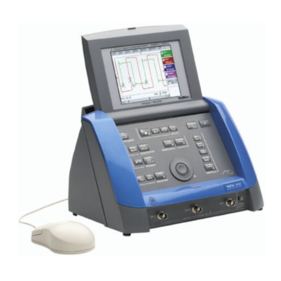
General instructions General Instructions You have just acquired a two-channel digital oscilloscope with “SPO” Introduction analog persistence display, 60 MHz or 100 MHz, ETHERNET. It can also features a « harmonic analyser » (option) mode and a « recorder » mode (option). Congratulations for your choice and thank you for your trust in the quality of our products. -
Page 5: Symbols Used
General Instructions General Instructions (cont’d) Warning: Risk of danger. Symbols Refer to the operating manual to find out the nature of the potential hazards and used the action necessary to avoid such hazards. Earth According to WEEE directive 2002/96/EC This equipment is guaranteed against any material defect or manufacturing Guarantee faults, in conformity with the general conditions of sale. -
Page 6: Presentation
Description of instrument Description of instrument Presentation This instrument has the particularity of grouping together 3 units in 1 : Smart • Persistence a Digital Oscilloscope incorporating the Oscilloscope FFT (Fast Fourier Transform) function and SPO (Analog Persistence Display) intended to analyze the signals appearing in the electronics and electrotechnical fields mtx 3x52 •... -
Page 7: Front Panel (Illustration)
Description of instrument Description of instrument (cont’d) Front panel (illustration) ACQUISITION HORIZONTAL TRIGGER VERTICAL Measurement terminal block CH1 signal input CH2 signal Input EXT input Calibrator output Two-channel digital oscilloscopes, 60 MHz or 100 MHz II - 7... - Page 8 Description of instrument Description of instrument (cont’d) Rear panel ETHERNET RJ45 USB connector connector USB to RS232 interface SUBD 25- pin female 6-pin MiniDin Mains plug connector connector for RS232/CENTRONICS PS/2 mouse interfaces II - 8 Two-channel digital oscilloscopes, 60 MHz or 100 MHz...
- Page 9 Description of instrument Description of instrument (cont’d) Front panel The main features of the equipment can be obtained from the front panel. They can also be modified directly by the mouse or using the menu toolbar. description) 1 startup / standby activates: button •...
-
Page 10: Preparation For Use
Description of instrument Description of instrument (cont’d) Preparation for use Before initial startup: Instructions before startup • Connect the mouse to the PS/2 connector at the back of the unit. • Check the power supply cord which will be connected to the back of the unit and to the grounded mains is in good condition. -
Page 11: Ethernet Network
Description of instrument Description of instrument (cont’d) ETHERNET network ETHERNET and TCP/IP (Transmission Protocol/Internet Protocol) are used to General principles communicate on a company's network. of the ETHERNET network Each piece of equipment under TCP/IP has a physical address (ETHERNET) Addressing and an Internet address (IP). - Page 12 Description of instrument Description of instrument (cont’d) SUBNET mask and If the result of the operation ' ET LOGIQUE' between IP address of the GATEWAY recipient of the message and the value of subnet mask is different from the address of the recipient of the message, this message is sent to the gateway which will be given the responsibility to forward it to destination.
-
Page 13: Keys
Oscilloscope Mode - Keys Oscilloscope Mode Keys Pressing this key will configure the instrument in the following modes: « oscilloscope », « harmonic analyser » (option), « recorder » (option). 4 «UTILITY» keys used for access to the LCD contrast adjustment using the thumbwheel. The LED combined with the thumbwheel comes on adjustment is accessible. - Page 14 Oscilloscope Mode - Keys Oscilloscope Mode (cont’d) 2 «ACQUISITION» keys by successive pressing, select one of the following acquisition modes: Single mode Single Trigger mode Trig’d Automatic mode Auto « SINGLE » mode: A single acquisition is triggered by pressing the RUN STOP key. For any further acquisition, the triggering circuit must be reset by pressing the RUN STOP key.
- Page 15 Oscilloscope Mode - Keys Oscilloscope Mode (cont’d) 3 « MEASUREMENT » keys activates or deactivates the display of the window for the 19 automatic measurements of the reference trace. Combined pressing with the CHx key displays the measurements on the corresponding channel.
- Page 16 Oscilloscope Mode - Keys Oscilloscope Mode (cont’d) Definition : Validated channel = Display enable (trace displayed after RUN) Displayed channel = Validated channel and trace on screen Selected channel = Parameter settings enabled for this channel via the opposite key. Before pressing one of the Press After pressing one of the 4...
-
Page 17: Display
Oscilloscope Mode - Display Oscilloscope Mode (cont’d) Display in oscilloscope mode Displays a warbled triangular signal View serial bus Data in envelope mode. The modulation amplitude in Envelope In this mode, the absence of accumulation of mode may be seen on the screen. All successive acquisitions and multi-colour display points displayed at the same colour and does not show infrequent signals. - Page 18 Oscilloscope Mode - Display Oscilloscope Mode (cont’d) 1. Status zone Three types of general information appear in this zone: • the bargraph represents the screen position, that of the trigger and the cursors in the acquisition memory • permanent instrument settings •...
- Page 19 Oscilloscope Mode - Display Oscilloscope Mode (cont’d) 2. Control zone The parameters displayed in this zone are: • The parameters of each channel and trace: display, sensitivity, coupling, bandwidth limit, vertical scale, function, zoom. • The time base value and the loading of the signal representation domain •...
- Page 20 Oscilloscope Mode - Display Oscilloscope Mode (cont’d) The « Source » and « Trigger mode » menus are grouped together and can be opened using the right mouse button by placing the pointer over the time base zone. RUN/STOP is used for starting and stopping acquisition from this menu. The acquisition status is indicated in the screen status.
- Page 21 Oscilloscope Mode - Display Oscilloscope Mode (cont’d) Display elements > ϕ ϕ ϕ ϕ ∨ ∨ ∨ ∨ Definition of Items Elements display Trace displayed Indication of displayed trace reference level vertical position Trace affichée Indication of time-related position of trigger Graticule division Automatic measurement cursor position indicator Manual measurement cursor position indicator...
- Page 22 Oscilloscope Mode - Display Oscilloscope Mode (cont’d) Menu accessible When the mouse pointer is placed in the display zone, from display zone the right key gives direct access to a display menu. The « Full Screen » and « Zoom out » options are directly accessible (see the Display menu).
- Page 23 Oscilloscope Mode - Display Oscilloscope Mode (Cont’d) Example of an Expanded area (in blue) expanded area Normal mode screen Expanded mode screen 4. Menu bar All the oscilloscope functions can be accessed by the main menus. Two-channel digital oscilloscopes, 60 MHz or 100 MHz III - 23...
- Page 24 Oscilloscope Mode - The « Vertical » Menu Oscilloscope Mode (cont’d) The « VERT » Menu 15MHz (∗) Only available in advanced mode if the SPO mode is not selected. See §. Description, page 65. III - 24 Two-channel digital oscilloscopes, 60 MHz or 100 MHz...
-
Page 25: Display
Oscilloscope Mode - The « Vertical » Menu Oscilloscope Mode (cont’d) Display opens the « Trace display » menu for validating or devalidating the traces. Validation of selections by « OK ». Exit from menu without modification by « Cancel ». The «... - Page 26 Oscilloscope Mode - The « Vertical » Menu Oscilloscope Mode (cont’d) Measure unit modifies the vertical scale unit of the selected channel. The modification is carried out by the mouse using the table of characters that can be used after selecting the “measure unit” zone. key is used for deleting the character leading the cursor in this zone.
- Page 27 Oscilloscope Mode - The « Vertical » Menu Oscilloscope Mode (cont’d) Examples • Predefined divv() function used on its own: math3 = divv(3). Use of predefined mathematical functions The trace is equal to 3 vertical divisions. divv(3) = 3 x 32000 LSB = 3 vertical divisions •...
- Page 28 Oscilloscope Mode - The « Vertical » Menu Oscilloscope Mode (cont’d) Example 1 Appropriate use of the operators for display Vhigh optimisation Sensitivity: Ch1 = Ch2 = 1 V/div Vpp: Ch1 = Ch2 = 6 V Vhigh: Ch1 = Ch2 = 3 V Traces ch1 and ch2 are optimised on 6 vertical divisions.
- Page 29 Oscilloscope Mode - The « Vertical » Menu Oscilloscope Mode (cont’d) For immediate interpretation of the results, configure the "Vertical scale" menu of mathx (see §. Opening from math1, math2, math3, math4 p. 35). In our example: • The sum of ch1 + ch2 is the sum of two values in volts, so the result is expressed in volts.
- Page 30 Oscilloscope Mode - The « Vertical » Menu Oscilloscope Mode (cont’d) Example 2 Sensitivity: Ch1 = Ch2 = 5 V/div Vpp: Ch1 = Ch2 = 10 V Vhigh: Ch1 = Ch2 = 5 V Vhigh ch1 = 1 vertical division => 1 x 32000 LSB = 32000 LSBs Vhigh ch2 = 1 vertical division =>...
- Page 31 Oscilloscope Mode - The « Vertical » Menu Oscilloscope Mode (cont’d) For immediate interpretation of the results, configure the "Vertical scale" menu of mathx (see §. Opening from math1, math2, math3, math4 p. 35). In our example: • The multiplication of ch1 by ch2 is the multiplication of Volts by Volts, so the result is in square volts.
- Page 32 Oscilloscope Mode - The « Vertical » Menu Oscilloscope Mode (cont’d) Example 3 - math3 = divv(3)*sin (2*pi*t/10000). Association of predefined functions The trace obtained is a sine wave produced using the predefined sin (sine) function, according to its mathematical definition (2 x π x Frequency).
- Page 33 Oscilloscope Mode - The « Vertical » Menu Oscilloscope Mode (cont’d) Production of an math1 = sin (pi*t/divh(1))*exp(-t/divh(6))*divv(4) attenuated sine wave using predefined functions sin (pi*t/divh(1)) can be used to modify the number of periods. exp (-t/divh(6)) can be used to modify the level of attenuation. exp (-t) represents: exp(-5000) when you reach the first horizontal division.
- Page 34 Oscilloscope Mode - The « Vertical » Menu Oscilloscope Mode (cont’d) Files contains the list of the functions (.FCT) saved by the user, along with two predefined files. By selecting the name of the function with the left mouse button (function name in blue), you can transfer the definition of the function into the 2 lines provided for that purpose.
- Page 35 Oscilloscope Mode - The « Vertical » Menu Oscilloscope Mode (cont’d) Save backs up the definition of the function by the “File Copy “ menu. Extension «.FCT». Reset completely resets the function definition. After assigning a function to the ch1 (math1) or ch2 (math2) channels, «...
- Page 36 Oscilloscope Mode - The « Trigger » Menu Oscilloscope Mode (cont’d) The « TRIG » Menu III - 36 Two-channel digital oscilloscopes, 60 MHz or 100 MHz...
- Page 37 Oscilloscope Mode - The « Trigger » Menu Oscilloscope Mode (cont’d) Definition This range of portable oscilloscopes is equipped with "advanced triggers". • The "Main" tab can be used to choose and parameterize the main trigger source. • The "Delay" and "Count" trigger modes require parameterization of a second "auxiliary"...
- Page 38 Oscilloscope Mode - The « Trigger » Menu Oscilloscope Mode (cont’d) Coupling Selection of the filter for the main trigger source: AC coupling (10 Hz to 200 MHz): blocks the DC component of the signal DC coupling (0 to 200 MHz): allows the entire signal through LF Reject Rejection of source signal frequencies <...
- Page 39 Oscilloscope Mode - The « Trigger » Menu Oscilloscope Mode (cont’d) The trigger is set with channel 1 as the source and a level of 2.04 V, on an ascending edge. The Holdoff stabilizes the signal by disabling the trigger for 108 µs. The DC coupling of the trigger lets the whole signal through.
- Page 40 Oscilloscope Mode - The « Trigger » Menu Oscilloscope Mode (cont’d) Delay Selection of edge trigger with delay The delay is triggered by the auxiliary source. Effective triggering occurs after the end of the delay on the next event from the main source.
- Page 41 Oscilloscope Mode - The « Trigger » Menu Oscilloscope Mode (cont’d) Example Signal injected on CH1: a train of three 6 V pulses at a frequency of 20 kHz separated by 500 µs. Selection of the trigger delay applied to the main source from 20 ns to 10,5 s Selection of the...
- Page 42 Oscilloscope Mode - The « Trigger » Menu Oscilloscope Mode (cont’d) Edge Selection of the trigger edge of the auxiliary source trigger on ascending edge trigger on descending edge Level 454mV Adjustment of the trigger level of the auxiliary source with the mouse on the scroll bar.
- Page 43 Oscilloscope Mode - The « Trigger » Menu Oscilloscope Mode (cont’d) Trigger on a TV line Standard Trigger on a specific line number. The trigger starts on the front edge of the line synchronization signal. • 625 lines (SECAM) or •...
- Page 44 Oscilloscope Mode - The « Trigger » Menu Oscilloscope Mode (cont’d) The 3 following selections define the trigger mode : Acquisitions and refreshment of the screen at each trigger event. Triggered mode Automatic mode Acquisition and automatic refreshing of screen even when there is no trigger event.
- Page 45 Oscilloscope Mode - The « Horizontal » Menu Oscilloscope Mode (cont’d) The « HORIZ » Menu (∗) (∗∗) (∗) Only available in advanced mode, if the SPO Persistence mode is not selected. See §. Description, page 65. (∗∗) The FFT function is not available in SPO Persistence mode.
- Page 46 Oscilloscope Mode - The « Horizontal » Menu Oscilloscope Mode (cont’d) Averaging This menu is used for selecting a coefficient to calculate an average for the displayed samples. For instance, this is a way of attenuating random noise observed in a signal. No averaging The averaging coefficient are: no averaging...
- Page 47 Oscilloscope Mode - The « Horizontal » Menu Oscilloscope Mode (cont’d) Square signal on ch2 of 10 kHz and 5 Vpp Attention : The modification of the sensitivity in FFT mode applies to the Cursor 2 Cursor 2 input signal. Check that the signal observed is not FFT with a rectangular window and a...
- Page 48 Oscilloscope Mode - The « Horizontal » Menu Oscilloscope Mode (cont’d) The sub-menus are used for selecting a type of window. Rectangular Hamming Hanning Blackman Before calculating the FFT, the oscilloscope weights the signal to be analyzed by a window acting as a bandwidth filter. The choice of window type is essential to distinguish between the various beams of the signal and to make accurate measurements.
- Page 49 Oscilloscope Mode - The « Horizontal » Menu Oscilloscope Mode (cont’d) The final duration of the design interval results in a convolution in the signal frequency domain with a function sinex/x. This convolution modifies the graphic representation of the FFT because of the side lobes characteristic of the sinex/x function (unless the interval of design contains an integer of periods).
- Page 50 Oscilloscope Mode - The « Display » Menu Oscilloscope Mode (cont’d) The « DISPLAY » Menu (∗) (∗) Only available in advanced mode if the SPO Persistence mode is not selected. See §. Description, p. 65. LCD contrast and brightness adjustment. LCD adjustment This function has the same effect as the following key.
- Page 51 Oscilloscope Mode - The « Display » Menu Mode Oscilloscope (cont’d) Full screen causes changeover from the normal display mode to the “full screen” display mode and vice versa. Attention This function is inactive if the SPO Persistence mode is activated. The display is organized so as to leave the biggest surface area possible for trace plotting: only the permanent settings and the automatic or manual measurements remain...
- Page 52 Oscilloscope Mode - The « Display » Menu Mode Oscilloscope (cont’d) The “XY source” menu is used for assigning the desired traces to the X axes (horizontal) and Y axes (vertical). (inactive in SPO) Validation of selections by “OK”. Exit from menu without modification by “Cancel”.
- Page 53 Oscilloscope Mode - The « Measurement » Menu Oscilloscope Mode (cont’d) The « MEASURE » Menu (∗) Only available in advanced mode, if the SPO Persistence mode has not been selected. See §. Description, page 65. The Automatic Measurements, the Phase Measurement of and the Attention Unattached Cursors are not available in “Persistence SPO”...
- Page 54 Oscilloscope Mode - The « Measurement » Menu Oscilloscope Mode (cont’d) • It is possible to select two permanent measurements. • The « » symbol indicates the measurement(s) that will be entered into the status zone. • Activating automatic measurements reveals two cursors (+) on the curve at the beginning and end of the period.
- Page 55 Oscilloscope Mode - The « Measurement » Menu Oscilloscope Mode (cont'd) • Measurement The measurements are made on the displayed part of the trace. conditions • Any change to the signal will lead to an updating of the measurements. They are refreshed in step with acquisition. •...
- Page 56 Oscilloscope Mode - The « Measurement » Menu Oscilloscope Mode (cont'd) Phase measurement used for making trace phase measurements with respect to a reference trace (See §. Reference Measurement). This menu selects the trace on which phase measurements are to be made. Trace1 Phase Trace2 Phase To deactivate phase measurements, de-select it using the same menu for...
- Page 57 Oscilloscope Mode - The « Measurement » Menu Oscilloscope Mode (cont'd) Unattached cursors used for linking or not linking the manual measurement cursors (1 and 2) to the reference trace. When the "Unattached cursors" menu is selected, cursors 1 and 2 can be moved freely over the screen.
- Page 58 Oscilloscope Mode - The « Memory » Menu Oscilloscope Mode (cont'd) The « MEMORY » Menu Trace1 Ref. 1 used for storing the selected trace in its volatile reference memory E.g.: Trace 1 in Ref. 1). Trace2 Ref. 2 Trace3 Ref.
- Page 59 Oscilloscope Mode - The « Memory » Menu Oscilloscope Mode (cont'd) Trace This menu is used for saving (to the non-volatile memory) or recalling the trace of a reference memory. Saving can be in two formats: « .TRC » or «...
- Page 60 Oscilloscope Mode - The « Memory » Menu Oscilloscope Mode (cont'd) Recall.TRC when selected, opens a « File Copy » menu. In the pull-down Source menu is the .TRC file list recorded using the « Trace Recall.TRC » menu. The file name selected for recalling appears in gray. Selection is made using the left key of the mouse.
- Page 61 Oscilloscope Mode - The « Utilities » Menu Oscilloscope Mode (cont'd) The « UTIL » Menu xx/xx/06 xx/xx/07 01/12/03 (∗) (∗) USB : when the USB cord has been detected Two-channel digital oscilloscopes, 60 MHz or 100 MHz III - 61...
- Page 62 Oscilloscope Mode - The « Utilities » Menu Oscilloscope Mode (cont'd) Files Selection of the "File Management" menu. It contains the files which have been: • recorded since the instrument was first used • created since the last startup. The files will only be saved once and for all when the instrument is switched off using the ON/STD BY key : If there is a mains power cut during saving of the configuration, the files in the file manager will be lost.
- Page 63 Oscilloscope Mode - The « Utilities » Menu Oscilloscope Mode (cont'd) I/O port config. Selection of the "RS232" or "Network" menus. This menu can be used to configure the "serial" remote programming interface or the "network" interface (ETHERNET). RS 232 This interface uses the connector (SUBD25) at the back of the instrument.
- Page 64 Oscilloscope Mode - The « Utilities » Menu Oscilloscope Mode (cont'd) Hardcopy when selected, opens the « Hardcopy » menu. This menu is used for selecting the print format or the printer type, as well as the communication port that will be used for making hardcopies. The printer type or selected format will appear in gray.
- Page 65 Oscilloscope Mode - The « Utilities » Menu Oscilloscope Mode (cont'd) System used for sending the user information about the life of the equipment starting from commissioning. Startup sequences indicates the number of equipment starts. Use duration indicates the total utilization time in hours. Last calibration date indicates the date of the last equipment calibration.
- Page 66 Oscilloscope Mode - The « Help » Menu Oscilloscope Mode (cont'd) The « ? » Menu MTX3354, VX.XX/XXX Help when selected, opens the « Help » menu. This menu is used for activating on-line help using the equipment keys, in the same way as the key shown opposite. keys are used for scrolling through the description of the keys on the front panel.
- Page 67 Oscilloscope Mode with "SPO" - Keys - Display Oscilloscope Mode with "SPO" Smart Persistence Oscilloscope The Keys With "SPO", the keys operate exactly as described for the Oscilloscope mode without "SPO" (see p. 13). The message "Impossible in this mode!" is displayed if the key pressed is not active.
- Page 68 Oscilloscope Mode with "SPO" - Keys - Display Oscilloscope Mode with "SPO" (cont’d) Smart Persistence Oscilloscope Occurrence This provides a statistical dimension to the distribution of the samples. The colour or brightness highlight the irregularities in the signal. They are also used to differentiate between rare points and frequent points.
- Page 69 Oscilloscope Mode with "SPO" - Keys - Display Oscilloscope Mode with "SPO" (cont’d) Smart Persistence Oscilloscope 1. Status area Tool bar Bargraph: see p. 18. Adjustment: Refreshing of display: all the traces displayed on the screen are erased. Monochrome Multicolour Adjustment of persistence representation (see p.
- Page 70 Oscilloscope Mode with "SPO" - Keys - Display Oscilloscope Mode with "SPO" (cont’d) Smart Persistence Oscilloscope Menu accessible from When the mouse pointer is placed in the display zone, a right click gives display area direct access to a menu concerning the display. Note These options are also accessible via the Display menu in "SPO", see p.
- Page 71 Oscilloscope Mode with "SPO" - The "Vertical" menu Oscilloscope Mode with "SPO" (cont’d) Smart Persistence Oscilloscope The "VERT" menu (∗) (∗) These greyed functions (∗) (∗) are not available. (∗) Display See p. 25. ch1 ch2 ch3 ch4 See p. 25. The "TRIG"...
- Page 72 Oscilloscope Mode with "SPO" - The "Display" Menu Oscilloscope Mode with "SPO" (cont’d) Smart Persistence Oscilloscope The "DISPLAY" Menu (∗) (∗) (∗) (∗) (∗) The greyed functions are not available. Oscilloscope Select the "Oscilloscope" mode. The " " symbol indicates that this mode is active. SPO Persistence Select the "Smart Persistence Oscilloscope"...
- Page 73 Oscilloscope Mode with "SPO" - The "Display" Menu Oscilloscope Mode with "SPO" (cont’d) Smart Persistence Oscilloscope (SPO) opens a dialogue box giving access to all the specific "SPO" settings. Persistence parameters These settings are also available in the settings bar (see p. 69). selects the display duration (100 ms, 200 ms, 500 ms, 1 s, 2 s, 5 s, Duration 10 s, infinite) for the points acquired.
- Page 74 Oscilloscope Mode with "SPO" - The "Measurement" Menu Oscilloscope Mode with "SPO" (cont’d) Smart Persistence Oscilloscope The "Measurement" Menu (∗) (∗) This function is ticked because it is permanently active These functions are (∗) not available. Reference See p. 52 Trace 1 Trace 2 Trace 3...
- Page 75 Oscilloscope Mode with "SPO" - The "Memory" Menu Oscilloscope Mode with "SPO" (cont’d) Smart Persistence Oscilloscope The "MEMORY" Menu These greyed functions are not available. Trace 1 Ref. 1 These functions are not available. Trace 2 Ref. 2 Trace 3 Ref.
- Page 76 Oscilloscope Mode with "SPO" - The "Utilities" Menu - "Help" Oscilloscope Mode with “SPO” (cont’d) Smart Persistence Oscilloscope The « UTIL » Menu See p. 61. The « ? » Menu See p. 66. V - 76 Two-channel digital oscilloscopes, 60 MHz and 100 MHz...
-
Page 77: Installation
« » Harmonic Analysis Mode - Display « Harmonic Analysis » Mode Installation The « Harmonic Analysis » mode is an option of the oscilloscope which must be installed to function. The instructions of installation are on the diskette (readme.txt file) delivered with this option. - Page 78 « » Harmonic Analysis Mode - Display « Harmonic Analysis » Mode (cont’d) Composition Harmonic mode display is divided into 4 functional zones: 4. Menu base Direct access to current 1. Display zone adjustments Selection of fundamental or harmonic Display of 3.
- Page 79 « » Harmonic Analysis Mode - Display « Harmonic Analysis » Mode (cont’d) 3. Status zone The status zone returns the automatic measurements made on the signals and the selected harmonic. Signal Signal Information display about Information display about fundamental or selected traces harmonic The «...
- Page 80 Harmonic Analysis Mode - The « Vertical » Menu Harmonic Analysis Mode (cont'd) The « VERT » Menu 15MHz Display when selected, opens the "Trace display" menu used for validating or invalidating the traces. Validation of selections by « OK ». Exit from menu without modification by «...
- Page 81 Harmonic Analysis Mode - The « Vertical » Menu Harmonic Analysis Mode (cont'd) modifies independently the ch1 and ch2 channels parameters and the selected ch1 ch2 trace vertical scale. modifies the parameters of the selected channel. Sensitivity/Coupling modifies sensitivity of channel by scrollbar with left mouse key: from 2.5 mV to 100 Channel Sensitivity V/div.
- Page 82 Harmonics Mode - The « Horizontal » Menu Harmonic Analysis Mode (cont'd) The « HORIZ » Menu No averaging These menus are used for selecting an average rate to calculate an Average rate: 2 average according to the coefficient selected on the displayed Average rate: 4 samples.
- Page 83 Harmonic Analysis Mode - The « Display » Menu Harmonic Analysis Mode (cont'd) The « DISPLAY » Menu These menus allow the display, according to 3 groups, of the harmonic composition of one or four selected signals. Fund Harmonic 16 displays fundamental and first 15 harmonics.
-
Page 84: Memory" Menu
Harmonics Mode - The "Utilities" Menu - The "Help" Menu Harmonic Analysis Mode (cont'd) The « MEMORY » Menu See description in "Oscilloscope" mode, p. 58. In the "Harmonics" mode, this menu is limited to saving and recalling the instrument configuration. The «... -
Page 85: Installation
Recorder Mode - Keys Recorder Mode Installation The « Recorder » mode is an option of the oscilloscope which must be installed to function. The instructions of installation are on the diskette (readme.txt file) delivered with this option. The Keys Same as the ones described in the «... - Page 86 Recorder Mode - Keys Recorder Mode (cont’d) 2 "ACQUISITION " keys No action. (Pressing the key displays the message: “Impossible in this mode!”). This key has two functions: RUN = launches an acquisition STOP = stops an acquisition If the recorder is in memory display (see §. Memory Menu Recall “.REC”, p.
- Page 87 Recorder Mode - Keys Recorder Mode (cont’d) Validated channel: Display enabled, trace displayed after RUN Definition of terms used Displayed channel: Channel validated, trace present on the screen (id. “Oscilloscope” Selected channel: enables the modification of the sensitivity (V/div) of mode) this channel through the thumbwheel.
-
Page 88: Display
Recorder Mode - Display Recorder Mode (cont’d) Display Normal mode display The user views 500 points on the screen (in “MIN/MAX” mode) to eliminate the risk of information loss involving the 50,000 points in the memory. Display in The user views 500 The memory is fault capture and file points on the screen... - Page 89 Recorder Mode - Display Recorder Mode (cont’d) 1. Status area Three pieces of general information appear in this area: • The bargraph, representing the screen position and the cursors in the acquisition memory; • Instrument settings (fault capture mode, zoom, etc.); •...
- Page 90 Recorder Mode - Display Recorder Mode (cont’d) Bargraph In fault capture and file capture mode, the bargraph indicates the position of the screen and cursors in the acquisition memory. The main cursor is positioned on the displayed fault and the auxiliary cursor on the right of the screen.
- Page 91 Recorder Mode - Display Recorder Mode (cont’d) 2. Control area (cont’d) Measurement of sample The colour corresponds under auxiliary cursor to the colour of the trace. Display of trace Measurement of sample parameters: under main cursor - validity - DC coupling - bandwidth limitation - vertical measurement of sample under cursors...
- Page 92 Recorder Mode - Display Recorder Mode (cont’d) 3. Display area Graphic elements displayed associated with the traces in this area: • Vertical position indicator for the reference level of each trace • ZOOM area selection. • Main cursor (permanent, moved using mouse) located at the left of the screen by default.
- Page 93 Recorder Mode - Display Recorder Mode (cont’d) Display elements Definition of display Items Display elements Trace displayed Indication of vertical position of reference level of the displayed Trace displayed trace and identification of trace number Indicator of trace outside display window Graticule division Zoom area selection Main measuring cursor...
- Page 94 Recorder Mode - Display Recorder Mode (cont’d) Menu accessible Like in “Oscilloscope” mode, the menu concerning the display can be opened from display area directly by clicking with the right key of the mouse in the display area. This menu, as well as the functions of the proposed options, are identical to those in “Oscilloscope”...
- Page 95 Recorder Mode - Display Recorder Mode (cont’d) Case 2 The horizontal zoom is enabled, the screen displays the captured fault which has been selected : A zoom frame is drawn. Fault capture mode: the horizontal zoom is enabled. A single fault is displayed on the screen. On the displayed fault, it is possible to vertically zoom delimitating a zone with the mouse.
- Page 96 Recorder Mode - « Vertical » Menu Recorder Mode (cont’d) This menu is identical to that described in “Oscilloscope” mode. The "VERT" Menu (∗) (∗) (∗) (∗) 15MHz (∗∗) (∗) (∗∗) The DC coupling is the only Functions only accessible in option in “Recorder”...
- Page 97 Recorder Mode - “Trigger” Menu Recorder Mode (cont’d) The "TRIG" Menu Selection of trigger type and level on each channel. Triggering takes place if a Triggering condition described by a line of the “Trigger” table is verified. This trigger level must be present in the display area. Source Indicates the channel number.
- Page 98 Recorder Mode - “Trigger” Menu Recorder Mode (cont’d) - Channel 1 is set with a 1.36V “higher than” trigger. Example - Math 3 and 4 do not wait for a trigger. - Channel 2 is set with an “outside” type trigger. - Channel 1 and 2 lines are highlighted: they wait for a trigger.
- Page 99 Recorder Mode - “Trigger” Menu Recorder Mode (cont’d) Fault capture The fault capture mode allows 100 recordings of 500 samples to be made around the trigger point. These 10 recordings will be displayed on the screen. Each recording is separated by a solid vertical line. They are recorded in volatile memory. Example The fault capture mode is selected: the screen is divided into 10 sections.
- Page 100 Recorder Mode - “Trigger” Menu Recorder Mode (cont’d) • File capture When the memory is full, the acquisition is stopped and a message appears (cont’d) on the screen “Write error/Auxiliary storage full!”. The message is validated by selecting OK with the mouse. The user can then begin to study the recordings.
- Page 101 Recorder Mode - “Trigger” Menu Recorder Mode (cont’d) Two cases arise: Display (fault capture, • the horizontal zoom is enabled, file capture) • the horizontal zoom is disabled. Horizontal zoom Modification of display: disabled • The cursors are no longer displayed. •...
- Page 102 Recorder Mode - “Horizontal” Menu Recorder Mode (cont’d) The "HORIZ" Menu Horizontal scale This function allows the user to set: - the recording time : variation range, from 2 s to 31 days - the sampling interval : variation range, from 40 µs to 53,57 s These two values are correlated.
- Page 103 Recorder Mode - “Display” Menu Recorder Mode (cont’d) The "DISPLAY" Menu LCD adjustment LCD contrast and brightness adjustment. This function has the same effect as the following key. Zoom off Returns to the original screen size after zooming in on part of the screen. •...
- Page 104 Recorder Mode - “Display” Menu Recorder Mode (cont’d) The search for faults enables successive recorderings in “fault capture” or Faults “file capture” (memory) mode to be explored (.REC). All files with a “.REC” extension are analysed and each fault is displayed. When one of these faults is selected, it is displayed on the screen.
- Page 105 Recorder Mode - “Measurement” Menu Recorder Mode (cont’d) The "MEASURE" Menu Reference Identical to “Oscilloscope” mode. Trace 1 Trace 2 Trace 3 Trace 4 This window is nearly identical to the one in "Oscilloscope" mode. Automatic measurements The automatic measurement calculation area is defined by the two cursors. It is not possible to select measurements in order to display them in the status area.
- Page 106 Recorder Mode - “Measurement” Menu Recorder Mode (cont’d) The "MEASURE" Menu Reference Identical to “Oscilloscope” mode. Trace 1 Trace 2 Trace 3 Trace 4 This window is nearly identical to the one in "Oscilloscope" mode. Automatic measurements The automatic measurement calculation area is defined by the two cursors. It is not possible to select measurements in order to display them in the status area.
-
Page 107: Memory" Menu
Recorder Mode - “Memory” Menu Recorder Mode (cont’d) The "MEMORY" Menu Trace Save .REC In this mode, all the traces are saved in one file (extension .REC). The selection opens a "File Copy" menu. A default backup filename is proposed above the keyboard. It can be modified using the virtual keyboard and mouse. - Page 108 Recorder Mode - “Memory” Menu Recorder Mode (cont’d) ‘.TXT’ save Identical to “Oscilloscope” mode (see §. Memory Menu Trace Save ‘.TXT’). In this mode, traces are saved individually. Recall ‘.REC’ Opens a "File Copy" menu when selected. In the "Source" list, the previously saved .REC files (via the menu "Trace Save.REC") are displayed.
- Page 109 Recorder Mode - “Memory” Menu Recorder Mode (cont’d) Configuration Saving or recalling an instrument configuration. Opens a "File copy" menu when selected. Save ∗ There is a file called “Configuration” in the “Source” list. It contains the configuration settings for the device at the time this menu is opened.
- Page 110 Recorder Mode - The “Utilities” Menu Recorder Mode (cont’d) The "UTIL" Menu xx/xx./06 xx/xx./07 Two-channel digital oscilloscopes, 60 MHz or 100 MHz VI - 109...
- Page 111 Recorder Mode - The “Utilities” Menu Recorder Mode (cont.) Files This function is identical to that described in “Oscilloscope” mode. Identical to “Oscilloscope” mode. I/O port config Identical to “Oscilloscope” mode. Screen shot Identical to “Oscilloscope” mode. Configuration • Screen saver If the recording time is over 2 seconds, the screen saver will never be activated.
- Page 112 Recorder Mode - « Help » Menu Recorder Mode (cont’d) The "?" Menu MTX3x52, Vx.xx/xxx Menu identical to “Oscilloscope” mode. Help Menu identical to “Oscilloscope” mode. About Two-channel digital oscilloscopes, 60 MHz or 100 MHz VI - 111...
-
Page 113: Calibration Signal Display
Applications Applications 1. Calibration signal display • Connect the calibrator output (2.5 V, 1 kHz) of the connection zone to the CH1 input using the 1: 10 ratio measurement probe (for instance). • Using the key shown opposite, select the « Oscilloscope » mode. ∗... -
Page 114: Automatic Measurements
Applications Applications (cont'd) • 3. Automatic Connect the calibrator output (2.5 V, 1 kHz) of the connection zone to measurements the CH1 input using a ratio 1 : 10 measurement probe. • For probe adjustments, see the §. Calibration signal display. •... -
Page 115: Cursor Offset Measurements
Applications Applications (cont'd) • 4. Measurements by Select measurements by cursors using the menu: Measurement cursors Manual measurements (dt, dv) (see §. Measurement). ∗ Two measurement cursors (1 and 2) are displayed as soon as the menu has been activated. ∗... - Page 116 Applications Applications (cont'd) • Note The 3 measurement cursors are present if there is at least one trace on the screen. • The 3 measurement cursors can be moved directly over the screen using the left mouse key. They can also be moved by the mouse, by selecting 1 (cursor 1) or 2 (cursor 2) in the status zone bargraph.
- Page 117 Applications Applications (cont'd) • Select the trigger mode: Trig. Menu Automatic mode or using the opposite key. • Use opposite key to start acquisition (RUN mode) or use the time base menu. The acquisition status (Ready, RUN, STOP) is indicated on the right, under Reminder the display of the trace, in the trigger status display zone.
- Page 118 Applications Applications (cont'd) 7. Examination of a For more detailed examination of a video line signal, the TV trigger menu specific TV line can be used to select a line number. • In the Trigger Parameters menu, select the tab: Trig.
-
Page 119: Spo » Applications
Applications Applications (cont'd) 8. "SPO" applications Select the "SPO" display mode in the "Display" menu of the "Oscilloscope with SPO" mode (see p. 72). a) "Statistical This example shows the third dimension of the "SPO" display: occurrence. Distribution" To do this, a signal representing several stable voltages (plateaux) is injected on the terminals of a capacity. - Page 120 Applications Applications (cont'd) "Statistical Below, the same signal observed without "SPO" and with the "Envelope" Distribution" display mode validated (see p. 50). (cont’d) Start of Recharge discharge phase Different voltage levels: with this representation, it is still possible to observe the overall shape of the signal. However, there is no longer any indication regarding repair of the different voltage levels.
- Page 121 Applications Applications (cont’d) b) "Rare event" This second application shows the speed and the cumulation of the "SPO" acquisitions. For certain signals, the user needs to search for intermittent anomalies. If you do not know exactly what you are seeking, it is very difficult to detect the problem.
-
Page 122: Automatic Measurements In Harmonic Analysis Mode
Applications Applications (cont’d) 9. Automatic Initially, a frequency signal between 40 Hz and 5 kHz must be injected to measurement in ch1 or ch2 channel. Harmonic Analysis mode Note - Only the channels (and not the functions) can be the subject of harmonic analysis. - Page 123 Applications Applications (cont'd) • The « Ref.: Harmonic X » » feeds into the selected harmonic: its value as a % of the fundamental its phase in ° with respect to the fundamental its frequency in Hz its RMS voltage in V Example harmonic breakdown On ch1 : the signal of the output calibrator (2.5 V, 1 kHz) (see §.
-
Page 124: Display Of Slow Events
Applications Applications (cont'd) 10. Display of slow The purpose of this example is the analysis of slow events for time bases events ranging from 200 ms to 200 s. « ROLL Mode» The samples are displayed constantly without waiting for the Trigger ("Roll"... -
Page 125: Measurements In « Recorder » Mode
Applications Applications (cont'd) 11. Measurement in Example : Monitoring of a voltage variation and detection of a level « Recorder » mode crossing Select the “Recorder” mode with the opposite key. Then check that the normal mode is active (‘Fault capture’ and ‘File capture’ modes not active. - Page 126 Applications Applications (cont'd) • Launch the acquisition using the opposite key. Trigger source : CH1 Trigger level : 6 V Trigger point Trigger : greater than Trigger time The acquisition stops when the signal overpasses the trigger level. Two-channel digital oscilloscopes, 60 MHz or 100 MHz VII - 125...
-
Page 127: Ethernet Network
Applications Applications (cont'd) 12. ETHERNET network application examples The files contained in the oscilloscope's "File management" menu (see "Util" a) File transfer via menu) can be transferred onto a PC (or the reverse) via an Ethernet the network network . Example Oscilloscope IP address = 132.147.240.1... - Page 128 Applications Applications (cont'd) b) Screen copy via Screen copying can be initiated on a network printer via an Ethernet the network network . Example Printer Oscilloscope IP address = 132.147.200.10 IP address = 132.147.200.74 ETHERNET network • Use of the FTP Use a suitable ETHERNET cable to link the oscilloscope to the network.
-
Page 129: Web Server
Applications Applications (cont'd) 13. Serveur WEB Minimum PC Configuration: Screens obtained on PC logged on to Pentium II, 200 MHz, 64 Mb. RAM. same network as the instrument. Screen resolution: > 1152 x 864 pixels In the examples that follow, the IP Install JVM SUN (minimum version address of the oscilloscope is: J2RE 1.4.2) from site //java.sun.com... -
Page 130: Oscilloscope » Mode
Applications Applications (cont'd) « Oscilloscope » Mode mouse click on window title IP address of triggers instrument : refreshing see p. 11 Window adjustments integrated by the scope after a click on "Remote Control". Attention If the SPO persistence mode is activated, the traces are not any longer displayed on the screen of the PC and the message «... - Page 131 Applications Applications (cont'd) « FFT » Mode mouse click on window title triggers refreshing Window adjustments integrated after a click on "Remote Control". « Recorder » mouse Mode click on window title triggers refreshing (∗) Window adjustments integrated after a click on "Remote Control".
- Page 132 Applications Applications (cont'd) « Harmonic Analyser » mouse click on Mode window title triggers refreshing Window adjustments integrated after a click on "Remote Control". « Utilities» selection button determines the action: launching of screen copy or file transfer Display of FTP window, indicating files on virtual...
- Page 133 Applications Applications (cont'd) File transfer IP address of instrument: Files may be see p. 11 copied on PC using conventional Windows commands. The Webserver does not work in Analyser mode. VII - 132 Two-channel digital oscilloscopes, 60 MHz or 100 MHz...
-
Page 134: Vertical Deflection
Technical Specifications Technical Specifications « Oscilloscope » Mode Only the values assigned with a tolerance or limits are guaranteed values (after half Vertical deflection an hour warming-up). Values without a tolerance are given for information only. Characteristics Specifications Comments Number of channels 2 channels: CH1 CH2 Type of inputs Class 1, common grounds... -
Page 135: Horizontal Deflection (Time Base)
Technical Specifications « Oscilloscope » Mode Technical Specifications (cont'd) Processing of measurements Mathematical functions Equation editor (functions on the channels or simulated) Addition, subtraction, multiplication, division and complex functions between channels. Automatic Time measurements Level measurements measurements rising time DC voltage falling time RMS voltage positive pulse... -
Page 136: Trigger Circuit
Technical Specifications Technical Specifications « Oscilloscope » Mode (cont'd) Trigger circuit Characteristics Specifications Comments Trigger sources CH1, CH2, EXT, Line Trigger mode Automatic Triggered Single shot Trigger coupling AC : BP 10 Hz to 60 MHz (MTX 3252) 100 MHz (MTX 3352) without bandwidth DC : BP 0 to 60 MHz (MTX 3252) -
Page 137: Acquisition Chain
Technical Specifications Technical Specifications « Oscilloscope » Mode (cont'd) Acquisition chain Characteristics Specifications Comments ADC Resolution 9 bits (22 LSB/div.) 1 converter per channel Maximum sampling frequency 100 MS/s Sampling modes 200 MS/s max. on one channel Real time (100 MS/s in « SPO ») (Single-shot signals) 100 MS/s max. -
Page 138: Miscellaneous
Technical Specifications Technical Specifications « Oscilloscope » Mode (cont'd) Display Characteristics Specifications Comments Display screen LCD 5.7 STN Color CCFL back-lit Contrast Continuous adjustment Resolution 1/4 VGA: i.e.: 320 pixels horizontal x 240 pixels vertical Screen saver Time selectable in Menu Util Configuration LCD zone reserved for traces... -
Page 139: Oscilloscope Mode With Spo
Technical Specifications Technical specifications of the "Oscilloscope Mode with SPO" Acquisition chain Sampling rate 100 MS/s max. Single shot Equivalent time ETS 25 GS/s max. Persistence parameters Settings Selection in the menu bar (p. 69) or the Display menu (p. 72) Duration 100 ms, 200 ms, 500 ms, 1 s, 2 s, 5 s, 10 s, infinite monochrome or multi-coloured... -
Page 140: Recorder » Mode
Technical Specifications « Recorder » Mode Technical Specifications Recording time from 2 sec. to 31 days Sampling frequency from 40 µs to 53.57 s Fault capture 100 faults in memory 200 faults in files Trigger on threshold high and low on threshold high or low Display Research minimum and maximum... -
Page 141: Communication Interfaces
Technical Specifications Technical specifications (cont'd) Communication interfaces USB type B connector is used to link the oscilloscope to the PC by an USB cable Situation at the back of the oscilloscope Interface « USB to RS232 », the configuration of the serial link is automatic at 921 600 bauds, HARD protocol, 8 bits, 1 bit stop, no parity. -
Page 142: Environment
General, Mechanical Characteristics General Characteristics • Environment Reference temperature 18° C to 28° C • Operating temperature range 0° C to 40° C • Storage temperature range - 20° C to + 60° C • indoor • Altitude < 2000 m •... -
Page 143: Accessories
Supply Supply Accessories • Operating and programming manuals on CD ROM Supplied with • instrument Mains power supply cord • Safety probes (x 2) • PS2 serial mouse • Mouse mat • ETHERNET network cord : cross over • USB cord •... - Page 144 INDEX date/time ............64 dc ..........16, 38, 40, 41 about ............66, 111 DC ..............54 AC ..........16, 38, 40, 41 delay ............37, 40 AC DC GND ..........25 delayed start-up ........89, 98 accessories ..........142 DISPLAY (menu) .......50, 72, 83, 103 ACQUISITION (keys) ......
- Page 145 INDEX Hamming ............48 menu bar ........13, 23, 70, 79 Hanning ............48 menus ..............9 hardcopy .......... 13, 64, 110 MiniDin connector ........6, 8, 10 harmonic analyser ........6, 13 minimum, maximum peak voltage ....54 harmonic analysis (mode ) ......77 mode ..............18 harmonics (even, odd) ........
- Page 146 INDEX startup ............9, 10 status zone .......9, 18, 69, 79, 89 ready .............. 14 step ...............26 rear panel ............8 STOP ............14 rec..............35 stop bits ............63 recall ..........75, 60, 108 SUBD connector ..........8 recall.rec ............107 SUBNET MASK ..........12 recall.trc ............
- Page 147 INDEX vertical scale ........25, 35, 81 vertical sensitivities ........13 Vhigh, Vlow ............ 54 video (direct, reverse) ........43 visualisation ........... 67 Vmax, Vmin, Vavg ......... 54 V-pos ............. 16 Vpp ..............54 Vrms .............. 54 XY ..............52 Z ..............
Need help?
Do you have a question about the MTX 3252e-C and is the answer not in the manual?
Questions and answers