Table of Contents
Advertisement
Quick Links
See also:
User Manual
Advertisement
Table of Contents

Related Manuals for Metrix MX 59HD


Summary of Contents for Metrix MX 59HD
- Page 1 MX 59HD Notice de fonctionnement User's manual Bedienungsanleitung Libretto d’istruzioni Manual de instrucciones ENGLISH - page 19 Chapter Copyright © X03052A00 - Ed. 04 - 02/13...
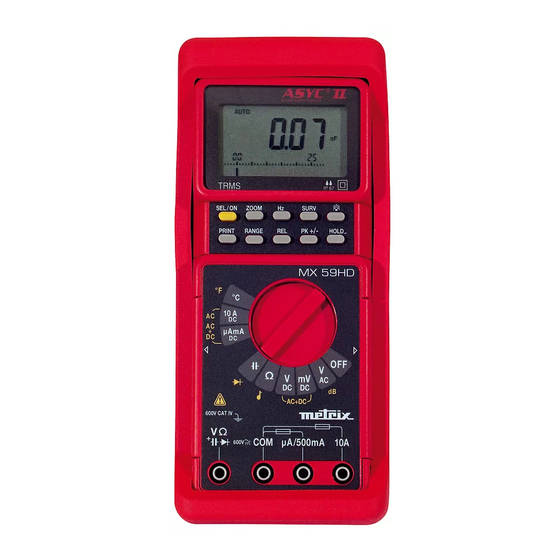
- Page 2 Multimètre digital portable...
- Page 3 LEGENDE / CAPTION / BESCHREIBUNG / LEGENDA / LEYENDA Borne d'entrée calibres 11, 12, 13, 14, 15 Mesure de tensions 500 mV Entrée de référence du multimètre Mesure de tensions continues Borne d'entrée calibre µA mA Mesure de résistance Borne d'entrée calibre 10 A Mesure de capacité...
-
Page 4: Table Of Contents
Chapter II CONTENTS 1. GENERAL INSTRUCTIONS......................... 20 1.1. Precautions and safety measures ....................20 1.2. Protection devices .......................... 21 1.3. Safety devices ..........................22 1.4. Warranty ............................22 1.5. Maintenance ........................... 24 1.6. Unpacking - Repacking ........................22 2. DESCRIPTION............................23 2.1. -
Page 5: General Instructions
Chapter II GENERAL INSTRUCTIONS You have just acquired a portable digital multimeter and we thank you for your confidence. This instrument complies with the specification of EN publication 61010-1, concerning safety requirements for electronic measuring apparatus. To get the best service from this instrument, read carefully this user's manual and respect the detailed safety precautions. -
Page 6: Protection Devices
Chapter II ∗ When performing current measurements, never change of range, do not connect or disconnect leads without first isolating the current. If you do, there is a risk of generating surge currents which can blow the fuses or damage the instrument. ∗... -
Page 7: Safety Devices
Chapter II 1.3. Safety devices ∗ The battery unit and fuses cannot be accessed without first disconnecting the measuring leads. ∗ When measuring voltages above 24 V, the symbol blinks on the display. ∗ If the maximum range is repeatedly exceeded, an intermittent audible signal indicates the risk of electric shock. -
Page 8: Description
Chapter II DESCRIPTION This multimeter is one of the ASYC II (Advanced SafetY Concept, third generation) family, designed for a high degree of user safety, maximum protection and a hitherto unrivalled performance. 2.1. Selector switch It is a standalone, handheld professional measuring instrument, capable of measuring the following quantities (accessed by the ten-position rotary selector switch) : ∗... -
Page 9: Commissioning
Chapter II COMMISSIONING 3.1. Connecting the test leads Connect the black lead to the COM socket (for all measurements). Depending on the position of the selector switch, connect the red lead as follows: Rotary selector switch position Input terminal , Ω, , °C , mV VΩ... -
Page 10: Multimeter Maintenance
Chapter II 3.5. Multimeter maintenance 3.5.1. Fuse self-test When fuse F1 (0.63 A) or F2 (11 A) is blown, the display shows “FUSE.1” or “FUSE.2”, accordingly. If both fuses are blown, the display shows “FUSES”. Replace the fuse or fuses concerned. μ... -
Page 11: Functional Description
Chapter II FUNCTIONAL DESCRIPTION 4.1. SEL/ON key This can be used to switch on the multimeter again after an automatic shutdown. It can also be used to access secondary functions associated with the selector switch positions. The flowcharts below define these various functions. 4.1.1. - Page 12 Chapter II 4.1.3. position DC Voltage measurement SEL/ON AC+DC Voltage measurement SEL/ON 4.1.4. Ω position Resistance measurement SEL/ON Continuity test SEL/ON 4.1.5. position Capacitance measurement SEL/ON Diode voltage measurement SEL/ON Portable digital multimeter...
- Page 13 Chapter II 4.1.6. µA mA / 10 A positions DC current measurement SEL/ON AC current measurement SEL/ON AC+DC current measurement SEL/ON 4.1.7. °C Position Temperature measurement SEL/ON > 1 sec. SEL/ON < 1 sec. Connections short- circuited Sensor selection Scale selection °C/°F Pt 100 / Pt 1000 Temperature measurement...
-
Page 14: Range Key
Chapter II 4.2. RANGE key • AUTO mode to switch to MANUAL mode (short press). • MANUAL mode, to select the next range (short press) or return to AUTO mode (long press). Measurements concerned : voltages (except 500 mV range), capacitance, resistance, current (except 10 A range). -
Page 15: Surv Key
Chapter II 4.7. SURV key If you press this key (long press), you access the surveillance mode (or coming out), in which minimum (MIN), maximum (MAX) and sliding average (AVG) values of the current measurement are stored. You can look up each of these values by repeatedly pressing the same key (short press). The symbols MIN, MAX or AVG flicker with the selected value. -
Page 16: Technical Specifications
Chapter II TECHNICAL SPECIFICATIONS Only those values assigned tolerances or limits are guaranteed values. Values without tolerances are given for information only (French standard NF C 42-670). The technical specifications are guaranteed only after 30 min warm-up period. Except special indication, they are valid from 5 to 100 % of the range of measurement. -
Page 17: Dc Current
Chapter II Curve showing typical measurement error (5 V, 50 V, 500 V ranges) Vin = 100 % F.S. 50000 pts Vin = 50 % F.S. 25000 pts Vin = 15 % F.S. 7500 pts Vin = 5 % F.S. 2500 pts 1000 pts 100 kHz... -
Page 18: Resistance / Continuity
Chapter II Number of counts : 50 000 (or 5 000, refer to §. 3.4.) Range selection : automatic or manual for the 500 µA, 5 mA, 50 mA, 500 mA ranges Additional error according to crest factor : 0.2 % for a crest factor of 2 to 3 0.5 % for a crest factor of 3 to 6 (Specification given full scale for a squarewave signal pulse 200 µs wide) Additional error in I... -
Page 19: Diode Threshold Voltage Measurement
Chapter II 5.7. Diode threshold voltage measurement Measurable voltages : 0 to 2 V Measurement current : 1 mA typical Resolution : 1 mV Protection : 600 V , can be reset automatically 5.8. Frequencies Selector switch setting : , mV, V , mA, 10 A Measurement range : 0.62 Hz to 500 kHz... -
Page 20: Temperature Function
Chapter II 5.10. Temperature function - temperature range : -200°C to + 800°C - resolution : 0.1°C ± 0.5°C from - 125°C to 75°C - accuracy : ± 1°C from - 150°C to 700°C - temperature sensors ∗ : platinum probes Pt 100 or Pt 1000 - unity ∗... -
Page 21: General Specifications
Chapter II GENERAL SPECIFICATIONS Adjustment The multimeter incorporates a non-volatile memory containing the adjustment characteristics for all measurement ranges. This enables the instrument to be re-adjusted via a serial link without opening the instrument. It is supplied with a certificate of verification. Safety According to EN 61010-1 Environment... -
Page 22: Accessories
Chapter II 6.1. Accessories 6.1.1. Supplied with the multimeter One set of test leads with safety probes One 6F22 9 V battery One spare 11 A fuse, 10 x 38 mm, rupture capacity 30 kA / 1000 V One spare 0.63 A fuse, 5 x 20 mm, rupture capacity 1.5 kA / 500 V One operating manual One rubber shock-absorber sheath 6.1.2. - Page 23 Capítulo V Fig. 1 Soulever la béquille située à Fig. 2 L'enlever en la tournant. l'arrière. Fig. 1 Lift the stand on the back. Fig. 2 Remove it by rotating. Abbg. 1 Die Klappstütze auf der Abbg. 2 Klappstütze durch Drehung Geräterückseite ausklappen.
Need help?
Do you have a question about the MX 59HD and is the answer not in the manual?
Questions and answers