Table of Contents
Advertisement
Quick Links
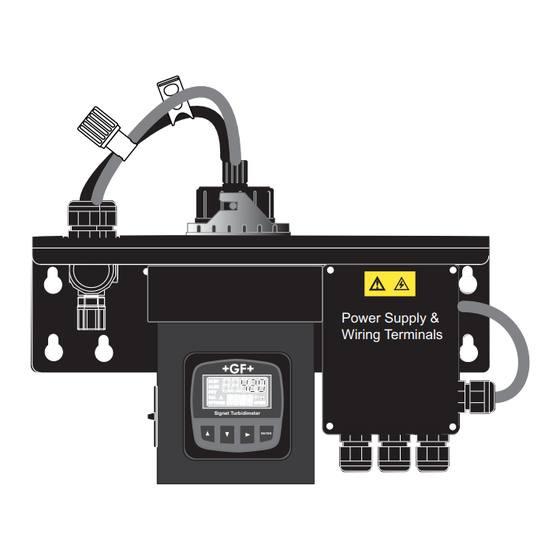
Signet 4150 Turbidimeter
*3-4150.090*
3-4150.090
Rev. P 03/15
Power Supply &
Wiring Terminals
Signet Turbidimeter
ENTER
•
English
•
Deutsch
•
Français
•
Español
Description
The Signet 4150 Turbidimeter provides accurate and reliable water quality monitoring
for municipal and industrial applications.
The 4150 uses the Nephelometric method to calculate the turbidity of a sample as it
fl ows through a viewing chamber. Models are available that use white light technology
as required by the U.S. EPA 180.1 standard, or select the models that use infrared
technology as required by ISO 7027.
Periodic calibration is mandatory with most turbidity systems, and the 4150 makes it
fast and easy with sealed, reusable primary calibration standards.
Two dry contact relays serve as high or low alarms, with programmable setpoints and
time-based delays to prevent false alarms.
Additional features include a bright backlight for the display and a convenient holder for
the cuvette during calibration.
An ultrasonic automatic cuvette cleaning system is standard for 0 to 100 NTU/FNU
systems and optional for 0 to 1000 NTU/FNU systems.
Table of Contents
Warranty Statement .............................................................................. 2
Product Registration ............................................................................. 2
Safety Information................................................................................. 2
Disclaimer ............................................................................................. 2
4150 Turbidimeter Parts ....................................................................... 2
Specifi cations........................................................................................ 3
Dimensions ........................................................................................... 3
Installation and Commissioning ............................................................ 4
Mounting Procedure ............................................................................. 4
Preassembly ......................................................................................... 4
Plumbing ............................................................................................... 5
Electrical Connections .......................................................................... 6
Overview of the Display and Keypad .................................................... 7
Display Icons and Functions ................................................................. 7
Security Feature ................................................................................... 8
Access to CALIBRATE Menu ............................................................... 8
Access to OPTIONS Menu ................................................................... 8
Calibration Standards ........................................................................... 9
Calibration Procedure .................................................................... 10-11
OPTIONS Menu.................................................................................. 12
Confi guring the 4 to 20 mA Output ..................................................... 12
Confi guring the RS-485 Output .......................................................... 13
Modbus RS-485 Output and Commands....................................... 14-16
Options: Alarm Relays ........................................................................ 17
Options: Instrument Offset .................................................................. 18
Options: Extended .............................................................................. 19
Vapor Purge System ........................................................................... 20
Replacing Desiccant ........................................................................... 20
Cleaning the Flow-Through Cuvette ................................................... 20
Ultrasonic Cleaning............................................................................. 21
Troubleshooting .................................................................................. 22
Notes .................................................................................................. 23
Ordering Information ........................................................................... 24
NOTE: This manual is for 4150 Turbidimeters manufactured after 3/10/2010.
If your menus look different than what is shown in this manual, you
have the earlier version. That manual (rev G) is available in the
Archived Products section at www.gfsignet.com.
Operating Instructions
English
Advertisement
Table of Contents

Subscribe to Our Youtube Channel
Related Manuals for GF Signet 4150


Summary of Contents for GF Signet 4150
-
Page 1: Table Of Contents
Rev. P 03/15 Operating Instructions Description The Signet 4150 Turbidimeter provides accurate and reliable water quality monitoring for municipal and industrial applications. The 4150 uses the Nephelometric method to calculate the turbidity of a sample as it fl ows through a viewing chamber. Models are available that use white light technology as required by the U.S. -
Page 2: Warranty Statement
Service Form and goods must be in the specifi cations on page 3 of this manual. returned to your local GF Sales offi ce or distributor. Product returned without a Service Form may not be Material Safety Data Sheets (MSDS) are available online at warranty replaced or repaired. -
Page 3: Specifi Cations
This device complies with Part 15 of the FCC rules. Operation is subject to the following two conditions: (1) This device may not cause harmful interference, and, (2) This device must accept any interference received, including interference that may cause undesired operation. Signet 4150 Turbidimeter... -
Page 4: Installation And Commissioning
Clean the glass cuvette with the special cleaning cloth that comes in the Calibration Kit. Signet Turbidimeter Do not use any other cloth. ENTER Insert the measuring cuvette assembly back into the instrument and rotate the locking ring clockwise to secure the assembly. Sensor Interconnect cable Signet 4150 Turbidimeter... -
Page 5: Plumbing
5. Reinstall the access door and rotate clockwise. NOTE: In regions where moisture or high humidity is prevalent, more than one desiccant pouch may be needed, and desiccant may need to be monitored more often. Desiccant Pouch 3-4150.380 Signet 4150 Turbidimeter... -
Page 6: Electrical Connections
• If power is removed from the 4150, the relays will be in an alarm state. 4150 Internal Power 4150 Internal Power Relay Coil Relay Coil Normally Open Common Normally Open Common Normally Closed External Power External Normally Closed Supply Power Supply Alarm Condition or Power Failure Normal Operation Signet 4150 Turbidimeter... -
Page 7: Overview Of The Display And Keypad
• The 4150 will return to normal operation if no keys are pressed in the OPTIONS menu for 10 minutes. NOTE: Pressing ▲ ► keys together and holding for 10 seconds resets ALL instrument parameters back to factory defaults. Signet 4150 Turbidimeter... -
Page 8: Security Feature
Display many single-set options like OFFSET is not a substitute for calibration, but it may be useful brightness and decimal location. if standard solutions are not readily available. (See OPTIONS: EXTENDED, pg. 19.) Signet 4150 Turbidimeter... -
Page 9: Calibration Standards
10 NTU and a 0.02 NTU standard. • If the Signet 4150 Turbidimeter will be used over the entire range, a 3-point calibration is required. • For best results, index new calibration standard cuvettes to the specifi c instrument before fi rst use. -
Page 10: Calibration Procedure
NTU value, while the lower display alternates the value of the NTU standard and Signet Turbidimeter Signet Turbidimeter ENTER ENTER • Press the ▼ key. The lower display will show the next NTU Standard value and Signet 4150 Turbidimeter... -
Page 11: Calibration Procedure
Use the 10 and 100 NTU cuvette daily to spot check the accuracy of the 4150. This eliminates the use of a hand-held device and reduces the amount of time to verify the accuracy of the 4150. NOTE: Replace the 10 and 100 NTU solutions after three months of use (90 days). Signet 4150 Turbidimeter... -
Page 12: Options Menu
Choose 2 mA, 4 mA, 0 mA, or OFF. This is an mA value that the 4150 will generate if there is a system failure. 9. Press the ENTER key to save the setting. Press the ▲ and ▼ keys simultaneously to exit the OPTIONS menu and return to normal operation. Signet 4150 Turbidimeter... -
Page 13: Confi Guring The Rs-485 Output
The 4150 has two transmission modes: Either ASCII (American Standard Code for Information Interchange) or RTU (Remote Terminal Unit). To prevent damage to the instrument, be sure that the 4150 is not powered when connecting the RS-485 line. Signet 4150 Turbidimeter... -
Page 14: Modbus Rs-485 Output And Commands
Valid Command(s) Code Name Broadcast 0x02 Read Input Status Format 16-bit word format Valid Addresses 10001–10XXX Defi nitions Address Function 10001 Instrument error 10002 Alarm 1 active 10003 Alarm 2 active 10004 Calibration error 10005 Desiccant error Signet 4150 Turbidimeter... - Page 15 Not used 40021, 40022 Float Alarm 2 set point 0.0 to max range of instrument 40023 Alarm 2 delay on 1–30 seconds 40024 Alarm 2 delay off 1–30 seconds 40025 Units (scaling) Valid Addresses 40001 – 40XXX Signet 4150 Turbidimeter...
- Page 16 The function code is not allowed in the device. ILLEGAL DATA ADDRESS The data address is not allowed in the device ILLEGAL DATA VALUE A value contained in the query fi eld is wrong for the device Signet 4150 Turbidimeter...
-
Page 17: Options: Alarm Relays
Press the ▼ key again to go to ALM2 display. Press the ► key to begin programming ALM2. The upper display begins blinking. Repeat steps 3 through 6. Press the ▲ and ▼ keys simultaneously to exit the OPTIONS menu and return to normal operation. Signet 4150 Turbidimeter... -
Page 18: Options: Instrument Offset
Offset. press the ▲ key to scroll to a positive offset value. If the OFFSET value is a NEGATIVE number, Scroll DOWN for press the ▼ key to scroll to a negative offset value. negative Offset. Signet 4150 Turbidimeter... -
Page 19: Options: Extended
Maximum adjustable limit is 3.6 mA to 4.4 mA (± 400 μA). OPTIONS: Extended: Adjust 20 mA Applies a ± 10% offset from 20 mA. Units are in microamps (μA). 100 microamps = 0.1 mA. Maximum adjustable limit is 18 mA to 22 mA (± 2000 μA). Signet 4150 Turbidimeter... -
Page 20: Vapor Purge System
• Unscrew the old cuvette and replace with a fresh clean one. Cuvette • Do not touch the glass surface of the cuvette. Fingerprints can compromise the accuracy of the measurement. Signet Turbidimeter ENTER Sensor Interconnect cable Signet 4150 Turbidimeter... -
Page 21: Ultrasonic Cleaning
• The Vapor Purge system will NOT remove large droplets of water, only residual moisture. The DRY message is normal and is not considered an alarm condition, therefore no alarms will be implemented. If the cuvette is removed during this period no CLN alarm is posted until the 30-minute DRY period times out. Signet 4150 Turbidimeter... -
Page 22: Troubleshooting
Troubleshooting Signet 4150 Fault Detection The Signet 4150 performs continuous diagnostic monitoring. There are three levels of fault detection: warnings, errors and failures. Warning A warning is simply a screen indication of a problem. The measurement is not interrupted and no alarms are activated. -
Page 23: Notes
Notes Signet 4150 Turbidimeter... -
Page 24: Ordering Information
Ordering Information Part Number Code Description 3-4150-1 159 001 596 Turbidimeter, White Light, 0 to 1000 NTU/FNU 3-4150-2 159 001 597 Turbidimeter, Infrared, 0 to 1000 NTU/FNU 3-4150-3 159 001 598 Turbidimeter, White Light, 0 to 100 NTU /FNU With AutoClean 3-4150-4 159 001 599 Turbidimeter, Infrared, 0 to 100 NTU/FNU With AutoClean...
Need help?
Do you have a question about the Signet 4150 and is the answer not in the manual?
Questions and answers