
Related Manuals for GF U1000 V2


Summary of Contents for GF U1000 V2
- Page 1 GF Piping Systems User Manual U1000 V2 Ultrasonic Flowmeter U1000 V2 HM Ultrasonic Heatmeter...
-
Page 2: Table Of Contents
7.3 Pipe mounting surface preparation ....................9 7.4 Start-Up ..............................10 7.5 Adjusting the sensor distance ......................11 7.6 Mounting the GF U1000 V2 on the pipe .....................12 7.6.1 Selecting the pipe adapter ......................12 7.6.2 Applying gel pads ........................13 7.6.3 Mounting the guide rail ......................13 7.6.4 Removing sensor-holding screws ..................14... - Page 3 Instruction Manual 9 Password-protected menus .........................24 9.1 Overview ..............................24 9.2 Opening a password-protected menu ....................25 9.3 Changing the selection in menus .......................25 9.4 Changing the numerical values in data menus ................26 9.5 Accessing the password-protected menu ..................27 9.6 Setup ................................27 9.7 Current output menu (4-20 mA versions only) ................29 9.8 Modbus setup menu (Modbus versions only) ..................29 9.9 Pulse output menu ..........................30...
-
Page 4: Intended Use
The GF U1000 V2 ultrasonic flowmeter is used to obtain an optimal measurement of the volume flow and flow rate in steel and plastic pipes with outside diameter from 22 mm (0.86”) to 180 mm (7”). Measurable pipe sizes are dependent on pipe material and inner pipe diameter. -
Page 5: Other Related Documents
Instruction Manual Other related documents • Georg Fischer industrial planning fundamentals These documents are available through agents of GF Piping Systems or at www.gfps.com. Abbreviations Abbreviation Description Acrylonitrile-butadiene-styrene Double acting function Electromagnetic Compatibility Fail safe to close function Fail safe to open function... -
Page 6: Design And Function
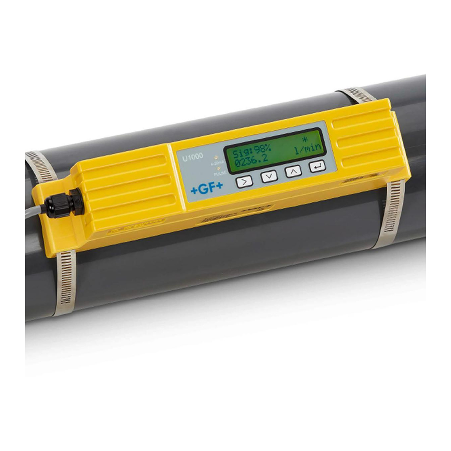
Electronics module Pipe The GF U1000 V2 consists of an electronics module (3) and a guide rail (4), which together form a single unit which is fixed to the pipe (6) by pipe clamps (2). The GF U1000 V2 is supplied with power through an external 12 – 24 V power adapter (1). -
Page 7: User Interface
Instruction Manual In addition to the flow rate, the GF U1000 V2 HM models measure the temperature difference between the flow and return of the system via two Pt100 temperature sensors. The difference in temperature between the flow and the return, in combination with the volume of water that has passed through the system, is used to calculate the energy difference in the medium. -
Page 8: Scope Of Delivery
Installation Identify suitable location for flow measurement The GF U1000 V2 requires an even and uniform flow profile, since distortions in the flow can cause unpredictable measurement errors. In many applications, however, it is not possible to have a uniform flow rate through 360°. This may be, for example, because there are air bubbles inside the top of the pipe, or turbulence in the pipe, or sludge at the bottom of the pipe. -
Page 9: Identify Suitable Location For Temperature Measurement (Hm Versions Only)
Instruction Manual NOTICE Incorrect Measurements Measurements can be distorted if the transducers are positioned close to upstream pipe components and fittings such as pipe bends, T-branches, valves, pumps and similar obstacles. To ensure the GF1000 V2 is positioned at a place that has an undistorted flow profile, the transducers must be mounted sufficiently far from possible sources of distortion to prevent these from having any effect on the measurement. -
Page 10: Start-Up
Pulse - Output (+), 4 to 20 mA Return (-), 4 to 20 mA Non-insulated shielding ►The GF U1000 V2 boots for the first time. The GF start screen is displayed for 5 s. +GF+ 4-20mA 000000 02/19 PULSE ►The start-up wizard automatically starts. -
Page 11: Adjusting The Sensor Distance
4 to 20 mA current output PULSE changes to a 3.5 mA alarm status. If the GF U1000 V2 does not detect a valid signal ‘Sig: 00%’ is shown. Sig : 00% 4-20mA In this case please make sure you followed the steps –... -
Page 12: Selecting The Pipe Adapter
Instruction Manual ► Define optimal sensor distance with entering your pipe credentials in the GF U1000 V2 start-up wizard (see section 8.4 Start-Up). (E.g. B-4 for PVC-U pipe with 50 mm inside diameter) ► Loosen the sensor mounting screws, sufficiently to loosen the flow sensors and allow sideways movement. -
Page 13: Applying Gel Pads
Instruction Manual Outside diameter less than Outside diameter Outside diameter more than 40 mm 40 mm – 60 mm 60 mm Top and bottom pipe Top pipe adapter (black) No pipe adapter adapters (black) 7.6.2 Applying gel pads Apply two a gel pads centrally onto the base of each of the two flow sensors. Remove the gel pad covers. -
Page 14: Removing Sensor-Holding Screws
Instruction Manual 7.6.4 Removing sensor-holding screws ► Mount the guide rail (1) and pipe adapters if necessary (see section 8.6.1 Selecting the pipe adapter) on the pipe (3) using the pipe clamps (2). ► Loosen the mounting screws and remove along with the washers.Release and remove the sensor-holding screws. -
Page 15: Moving The Guide Rail
Place replacement Gel pads down the centre of the sensor block. ► F ollow the procedure in section 8.6 Mounting the GF U1000 V2 on the pipe for re-installing the guide rail on the pipe. Attach the temperature sensors (U1000 V2 HM versions only) -
Page 16: Electrical Connection & Outputs
Electrical Connection and Outputs NOTICE The U1000GF U1000 V2 operates in the voltage range 12 – 24 V (AC/DC). The power supply must have a minimum rating of 7 VA per instrument. To fully meet the requirements of EMC regulations, a 12 V connection is recommended for domestic and light industrial applications. -
Page 17: Pulse Output
The Alarm functions allow you to set the alarm switch to Normally Open or Normally Closed. 8.2.1 Volumetric pulses The GF U1000 V2 default pulse width is set to 50ms which represents half of one pulse cycle. A 50ms pulse width is required for most mechanical counters. -
Page 18: Frequency Mode
Instruction Manual Formula to obtain Volume per Pulse based on a (default) 50ms pulse width: Volume per Pulse >= maximum flow rate (in litres per minute) / 600 Example for maximum flow rate of 500 l/min: Volume per Pulse >= 500 l/min / 600 = 0.833 litres per pulse Rounding up to nearest whole litre: Set Volume per Pulse to 1 litre. -
Page 19: Modbus Option
On a unit set to Imperial the temperature is in °F, Power is in BTU/s and flow in US Gallons. • The GF U1000 V2 complies with the Modbus specification document: http://www.modbus.org/ docs/Modbus_Application_Protocol_V1_1b.pdf Both of these faults will set the relevant status bit. The following registers are available. -
Page 20: Modbus Connections At Device
Cables of any specified length can be supplied to order +V (+5V or +12V) 270Ω for +5V, 1 KΩ for +12V 120Ω RS485+ 120Ω RS485- 270Ω Optional Ground GND (0V) Isolated Isolated Isolated RS-485 RS-485 RS-485 U1000 V2 U1000 V2 U1000 V2... - Page 21 Instruction Manual Modbus wiring without spurs Modbus Main +V (+5V or +12V) 270Ω for +5V, 1 KΩ for +12V 120Ω RS485+ 120Ω RS485- 270Ω Optional Ground GND (0V) Isolated Isolated Isolated RS-485 RS-485 RS-485 U1000 V2 U1000 V2 U1000 V2...
-
Page 22: Modbus Registers
Instrument Address Byte 0x03 Instrument Command Byte 0x40 Number of bytes to read - 0x00 0xAC 40001 Int-16 Device ID GF U1000 V2-(HM) 0xac 0x00 0x0000 OK 40002 Int-16 Status Not[0x0000] Fault 0x00 0x00 System Type 0x04 Heating system 40003... - Page 23 Instruction Manual Modbus Register Typical Type Meaning Notes Register Offset Contents 0x41 Units in Degrees Celsius for 40017 Measured Temperature 0x88 Metric iee754 (Cold) Units in Degrees Fahrenheit for 0x00 (HM versions only) 40018 Imperial 0x00 0x40 0x00 Units in Degrees Celsius for 40019 Measured Temperature Metric...
-
Page 24: Temperature Probes (Hm Versions Only)
Instruction Manual Temperature sensor (HM versions only) Two separate 4-core plug-in cables are provided for the Temperature Sensor connections. These plug into the right-hand side of the Electronics Module. U1000 V2 HM Temperature Sensor Wiring COLD White White White White... -
Page 25: Opening A Password-Protected Menu
Instruction Manual Opening a password-protected menu Signal strength and the present flow are displayed: Sig: 98% 4-20mA 0260.8 1/min PULSE ► P ress the button. You are prompted for the password. If the password is not entered, the display automatically changes back to the flow value after a few seconds. -
Page 26: Changing The Numerical Values In Data Menus
Instruction Manual Changing the numerical values in data menus NOTICE The procedure for changing numerical values is the same for all menus. In this example, the preset value for the flow at maximum current is changed from 1,000 l to 1,258 l. ►... -
Page 27: Accessing The Password-Protected Menu
Instruction Manual Accessing the password-protected menu ► Ensure that the instrument is in Flow Reading, Total Flow, Temperature dT, Total Energy, Instant Sig : 87% 4-20mA Power or Total Flow mode. 246.3 1/min ► Then press PULSE ► Enter 71360 and then press Enter Password : 4-20mA *****... - Page 28 Instruction Manual ► Choose the System Units. If you selected mm in the first step (Select Dim), the choice is litres or System Units : 4-20mA . If you selected Inches, the choice is Imperial Litres \ m3 gallons or US gallons. PULSE ►...
-
Page 29: Current Output Menu (4-20 Ma Versions Only)
Instruction Manual Current output menu (4-20 mA versions only) ► Enable or disable the 4-20mA output using select OFF or ON. Select 4-20mA : 4-20mA ► Press to confirm the setting. OFF | ON PULSE ► Enter the maximum flow. ►... -
Page 30: Pulse Output Menu
Instruction Manual Pulse output menu All models allow the use of a pulse output based on Volume pulse, Alarm, Energy pulse (Heat Meter versions only) or Frequency indicating flow rate. ► Enable or disable the Pulse output using select OFF or ON. Select Pulse : 4-20mA ►... -
Page 31: Energy Pulse (Hm Versions Only)
Instruction Manual 9.9.3 Energy Pulse (HM versions only) ► Choose from 1,10,100kWh or 1MWh when in metric mode and 1,10,100kBTU or 1MBTU in Energy Pulse : 4-20mA imperial mode. Each pulse represents the 1 k/Wh selected amount of energy e.g. 1kWh. Choose a PULSE value so that the pulse rate does not exceed 10 per second. -
Page 32: Volume Totals Menu
Instruction Manual ► Press to calculate the Zero Offset automatically. Note: Set ‘zero cut-off’ to zero before setting Zero Offset : 4-20mA ‘zero offset’ then go back to set ‘zero cut-off’. -0.005 m/s ► Press to confirm the setting. PULSE ►... -
Page 33: Diagnostics Menu
Instruction Manual 9.12 Diagnostics menu The diagnostics menu provides additional information and various diagnosis options. The menu can be accessed by pressing the key from the main flow-reading screen. Press the keys to move between the diagnostics screens. Press to exit the Diagnostics menu. The Estimated TA (Time of Arrival) and Actual TA show the theoretical and measured transit times. -
Page 34: Maintenance & Limitations
Instruction Manual Maintenance & limitations CAUTION Risk of injury and loss of product quality through the use of spare parts not provided by GF Piping Systems! Risk of injury and damage to property. ► If repairs are necessary, please contact your national agent for GF Piping Systems. -
Page 35: Troubleshooting
No Gel pad or grease on the sensor • Very poor pipe condition-surface/inside 11.2 Error messages Error Messages are displayed as a number in the diagnostics menu. Contact your GF sales representative if other messages appear. Status Byte Error meaning Value... -
Page 36: Example Error Messages
Instruction Manual 11.3 Example error messages Error Message Error Meaning None or 0 None Hot sensor error (HM versions only) Cold sensor error (HM versions only) Hot and Cold sensor error (HM versions only) No flow signal Hot error and no flow signal (HM versions only) Cold error and no flow signal (HM versions only) Hot and Cold error and no flow signal (HM versions only) 11.4... -
Page 37: Data Entry Errors
► Switch off the external power supply and prevent it from being switched on again. ► Disconnect all cable connections. ► Loosen the pipe clamps and remove the GF U1000 V2 completely from the pipe along with all connecting cables. -
Page 38: Specifications
USgal/s, USgal/min, m3/ min, m3/hr Selectable Totalizer Units liter, gallons, US gallons, m³ Languages supported Temperature sensors from U1000 V2 HM Operating Temperature 0 °C to 50 °C 32 °F to 122 °F Storage Temperature -10 °C to +60 °C 14 °F to 140 °F... -
Page 39: Default Values
Instruction Manual Housing and Display Material Polycarbonate Dimensions 250 x 48 x 90 mm 9.85 x 1.9 x 3.55 inch Weight 0.5 kg 1.1 lb Keyboard Keypad with 4 buttons Display Type LCD, 2 lines x 16 characters Viewing Angle Min. -
Page 40: Disposal
A product marked with this symbol must be taken to a separate collection point for electrical and electronic devices. If you have any questions regarding disposal of the product, please contact your national agent for GF Piping Systems. Rev 0 6/21...
Need help?
Do you have a question about the U1000 V2 and is the answer not in the manual?
Questions and answers