
Related Manuals for Clarke DWP300A


Summary of Contents for Clarke DWP300A
- Page 1 SUBMERSIBLE PUMP MODEL NO: DWP300A PART NO: 7239220 OPERATION & MAINTENANCE INSTRUCTIONS ORIGINAL INSTRUCTIONS GC0819 - ISS 1...
-
Page 2: Environmental Recycling Policy
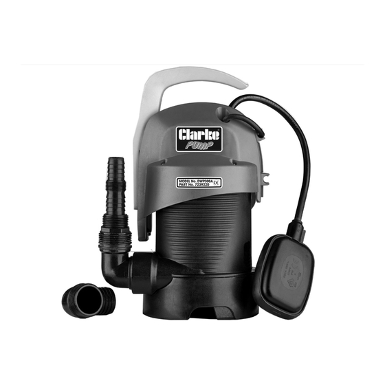
INTRODUCTION Thank you for purchasing this CLARKE submersible pump. The pump is designed for domestic use, such as drying out basements and garages subject to flooding, and for pumping drainage wells, rainwater collecting traps etc. Due to its compact shape, it is also used as a portable pump for emergency situations such as for drawing water from tanks or rivers, draining swimming pools and fountains, excavations or underpasses. -
Page 3: Specifications
SPECIFICATIONS Dimensions (L x W x H) 150 x 166 x 318/285 mm (handle raised/lowered Weight 4.2 kg Cable Length 10 m Power supply 230V ~ 50Hz Ingress protection IPX8 ¼ Outlet Thread Diameter “BSP female Rated Power 330 W Maximum Head Height 5.5 m Maximum particle size... -
Page 4: Safety Instructions
SAFETY INSTRUCTIONS GENERAL 1. Read all instructions before use and save them for future use. 2. An approved residual current device (RCD) which has a tripping current of less then 30mA MUST be used for all operations. 3. The electrical supply must be the same as that on the rating plate. 4. -
Page 5: Electrical Connections
9. NEVER use the submersible pump in a swimming pool when there are people or animals in the pool. 10. Keep the pump clear of any sediment by standing it on a platform or brick or suspending it at a suitable depth. 11. -
Page 6: Installing The Pump
(not supplied) to either the screwed end or push-fit • Suitable hoses are available from your local Clarke dealer. • The adaptor can be cut off with a hacksaw to provide clearance if required, when a larger hose is to be used. -
Page 7: Positioning The Pump
POSITIONING THE PUMP 1. Stand the pump upright on a flat surface in the pool that you want to drain. If there is sediment in the pool or pond, place the pump on blocks, to avoid blocking the water inlet. 2. -
Page 8: Maintenance
This pump should require no maintenance other than regular cleaning. If the pump shows signs of wear or damage contact your CLARKE dealer for advice. Check the pump regularly to ensure the water inlet is clear of leaves or other debris. -
Page 9: Troubleshooting
7. Water level too low - float switch in OFF position - lift float to check switch. 8. If the pump still fails to start, consult your CLARKE dealer for advice. PUMP WILL 1. Check that the inlet is not blocked. -
Page 10: Parts Diagram
PARTS DIAGRAM Ref No Description Lower insert Foot moulding Screw O-ring Upper insert Lower enclosure Motor stator Sealing ring Clip O-ring set Impeller O-ring Motor Bearing Motor rotor Main housing Sealing ring 17/18 Collet 19/20 Bush Upper enclosure Capacitor Clip Upper cover Gland Screw... -
Page 11: Declaration Of Conformity
DECLARATION OF CONFORMITY Parts & Service: 020 8988 7400 / E-mail: Parts@clarkeinternational.com or Service@clarkeinternational.com...
Need help?
Do you have a question about the DWP300A and is the answer not in the manual?
Questions and answers