Table of Contents
Advertisement
CHEM-PRO
®
Hybrid Metering Pump
®
PROSERIES-M
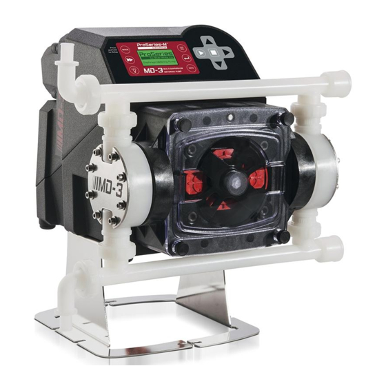
MD-3
Operating and Maintenance Manual
ProSeries
5
F IVE-YEAR
ProSeries
R
WARRANTY
TM
by Blue-White Ind.
R
Diaphragm Technology
5300 Business Drive, Huntington Beach, CA 92649
USA
Phone: 714-893-8529
FAX: 714-894-9492
E mail: sales@blue-white.com or techsupport@blue-white.com
URL: www.ProSeries-M.com
Advertisement
Table of Contents

Related Manuals for Blue-White PROSERIES-M CHEM-PRO MD-3


Summary of Contents for Blue-White PROSERIES-M CHEM-PRO MD-3
- Page 1 CHEM-PRO ® Hybrid Metering Pump ® PROSERIES-M MD-3 Operating and Maintenance Manual ProSeries F IVE-YEAR ProSeries WARRANTY by Blue-White Ind. Diaphragm Technology 5300 Business Drive, Huntington Beach, CA 92649 Phone: 714-893-8529 FAX: 714-894-9492 E mail: sales@blue-white.com or techsupport@blue-white.com URL: www.ProSeries-M.com...
-
Page 2: Table Of Contents
Introduction Congratulations on purchasing the MD-3 variable speed Hybrid Metering Pump. Please Note: Your new pump has been pressure tested at the factory with clean water before shipping. This is part of our stringent quality assurance program at Blue-White Industries. -
Page 3: Model Number Matrix
Page 3 MD-3 Model Number Matrix: CHEM-PRO ® ProSeries-M Multi-Diaphragm Metering Pump ® Multi-Diaphragm Model Number Matrix Engineering and Technical Data Model Number Matrix: Multi-Diaphragm Model Number Multi-Diaphragm Metering Pump MD-3 Maximum Strokes per Minute 190 RPM Input Voltage / Power Cord 115V / 60Hz, power cord NEMA 5/15 plug (US) 230V / 60Hz, power cord NEMA 6/15 plug (US) 220V / 50HZ, power cord CEE 7/VII plug (EU) -
Page 4: Specifications
Page 4 MD-3 Specifications Maximum working pressure*: Motor: 145 psig (10 bar), *model specific Brushless DC, 1/4 H.P. Maximum Fluid temperature: Duty cycle: 185 F (85 C) Continuous Maximum fluid viscosity: Motor speed adjustment range 2,000:1: 1,000 Centipoise 0.05% - 100% motor speed Maximum suction lift: Motor speed adjustment resolution: 23 ft. -
Page 5: Features
CNC precision machined cam and piston for optimum efficiency, unparalleled accuracy, and linearity. Heavy duty PVDF pump head and valves are standard. Compatible with Blue-White’s output Flow Verification Sensor (FVS) system. Includes stainless steel extended mounting brackets. Lifts pump 4-1/2” (11.43 cm), for easy access in hard to reach areas. -
Page 6: Installation
Page 6 MD-3 Installation CAUTION Always wear protective clothing, face shield, safety glasses and gloves when working on or near your metering pump. Additional precautions should be taken depending on solution being pumped. Refer to MSDS precautions from your solution supplier. CAUTION All diagrams are strictly for guideline purposes only. -
Page 7: Product Dimensions
Page 7 MD-3 Dimensions 16.13in 15.33in 40.97cm 38.95cm 15.25in 38.72cm 4.00in 10.15cm 7.18in 18.22cm 2.50in 8.86in 6.35cm 22.50cm 1.10in 21.08cm 8.30in 21.08cm Extended Brackets Stainless Steel extended brackets allow the pump to be securely mounted to most any surface; floor, shelf, or skid. Made out of tough Stainless Steel. -
Page 8: Input Power Connections
Page 8 MD-3 2.3 Input Power Connections WARNING Risk of electric shock – cord connected models are supplied with a grounding conductor and grounding-type attachment plug. To reduce risk of electric shock, be certain that it is connected only to a properly grounded, grounding-type receptacle. WARNING Electrical connections and grounding (earthing) must conform to local wiring codes. -
Page 9: Wiring Terminals And I/O Schematics
0-10 (+) GND (-) TRANSMITTER (-) NEGATIVE +15 VDC 4-20 (+) SOURCE INPUT: BLACK (-) (+) POSITIVE FVS SYSTEM BARE BLUE-WHITE (FLOW VERIFICATION SIGNAL FVS SENSOR SENSOR) FV SENSOR ONLY (-) NEGATIVE RED (+) INPUT: NEGATIVE (-) (+) POSITIVE FVS SYSTEM... -
Page 10: How To Operate Md-3
Page 10 MD-3 How To Operate MD-3 MD-3 Control Panel - Button Operation Press and hold MODE for Setup MD-3 MULTI-DIAPHRAGM INFO INFO METERING PUMP Press and release to select a Run Mode. Press and hold to enter the Press and release to enter the configuration menu for the currently configuration menus. -
Page 11: Menu Navigation
Page 11 MD-3 3.1 Menu Navigation – Sample screen shots – - Menu Use MENU button to enter menu for setting up pump. + Configuration + Input Setup Use UP or DOWN arrows to navigate through menu. + Output Setup + Power Fail option Active option appears on pump display in inverse... -
Page 12: Configuration Menu
Page 12 MD-3 3.2 Configuration Menu Below is the menu structure for the Configuration screens. - Menu + Configuration + Input Setup + Output Setup + Power Fail option <- Esc - Configuration - Configuration - Configuration - Configuration + Display Language + Display Language + Display Language + Display Language... -
Page 13: Display Rate (Units Of Measure)
Page 13 MD-3 3.2.2 Display Rate (Units of Measure) - Configuration + Display Language By default, the pump will display %Speed (motor speed) and RPM. It is + Set Password recommended you select an additional Display Rate. After selecting another + Display Rate Display Rate (such as ML/Min), the pump display may be toggled through + Reset to Factory Defaults... -
Page 14: Input Setup
Done Set Flow Verification time delay. Use this + Set FVS (select one) + Set DFD feature if you are using a Blue-White + Remote/Local + Set Rev Alarm flow verification sensor to monitor flow <- Esc output. Default setting is OFF. -
Page 15: Max Rpm Cut-Off
Page 15 MD-3 - Input Setup 4.1 Max RPM cut-off + Max RPM cut-off + Max Flowrate The maximum motor RPM can be limited to reduce the possibility of overfeeding + Input Modes chemical into the system. Note that the pump’s display will still reference values + Contact Input calculated from the 100% motor speed MAX Flowrate value (see section 4.2). -
Page 16: Input Setup (Operating Mode Configuration)
Page 16 MD-3 4.3 Input Setup (operating mode configuration) Run Mode (operating Input Mode) MODE button also serves as a Tip! shortcut button. Press and Hold MODE button to enter the programming menu for the MODE current Run Mode. After programming the Run Mode, press ENTER to save changes. -
Page 17: Ma Input
Page 17 MD-3 4.3.2 4 - 20 mA Input - 4-20 mA Input Min mA Signal: 4.00 Used to remotely control the pump with an incoming 4-20 mA signal. Input Min. mA signal Input. Default settings: 4 mA = 0% motor speed Press ENTER to set. -
Page 18: Vdc Input
Page 18 MD-3 4.3.3 0 - 10 VDC Input (Volt DC) - 0-10 VDC Input Min VDC Signal: 0.00 Used to remotely control the pump with an incoming 0-10 VDC signal. Input Min. VDC Default settings: 0 VDC = 0% motor speed Press ENTER to set. -
Page 19: Frequency Input (Hz)
Page 19 MD-3 4.3.4 Frequency Input (Hz) - Frequency Input Min Freq. Signal: Used to remotely control the pump with an incoming high speed frequency signal. Typically used with flow meters or other external devices. Input Min. Freq. (Hz) Press ENTER to set. Default settings: 0 Frequency (Hz) = 0% motor speed 1000 Frequency (Hz) = 100% motor speed... -
Page 20: Pulse Batch (Low Speed Batch)
Page 20 MD-3 4.3.5 Pulse Batch (low speed pulse) - Pulse Batch Input Pulse Num: Used to remotely control the pump with an incoming pulse signal. Can be used with an external foot pedal, a water meter, a PLC, contact closure, or other low Pulse num. -
Page 21: Manual Cycle Adjust (Repeating Cycle Timer)
Page 21 MD-3 - Cycle Adjust 4.3.6 Manual Cycle Adjust (repeating cycle timer) Input Flow Rate: 50.0 Used to operate the pump at a pre-selected motor speed for a specified run time. This cycle will repeat itself using a repeating cycle timer. Input Flow Rate. -
Page 22: Dispensing
Page 22 MD-3 4.3.7 Dispensing - Dispensing Volume to Dispense: 000010.0 Configure any dispensing amount or sample size and the pump will repeat it on command by pressing the START button. Great for accurate single shot dispens- Input mL to dispense. ing of a pre-configured volume. -
Page 23: Manual Dosing
Page 23 MD-3 4.3.8 Manual Dosing - Manual Dosing Dose Concentration: Used to configure Parts Per Million dosing to a system. This method can be 2.5% used if treated fluid volume is a fixed amount (in Liters Per Minute). If treated % of concentration. -
Page 24: Proportional Dosing
Example #2, Paddlewheel flow meter Paddlewheel Injection Injection Flow Sensor / Meter Point Point S3 Series | Hybrid Ultrasonic Flowmeter NEMA 4X IP 66 Ultrasonic Flow Meter Discharge Doppler / ProSeries Transit Time by Blue-White Ind. Industries, Ltd. Line Discharge Line... -
Page 25: Contact Closure Input (Remote Start/Stop)
Page 25 MD-3 4.4 Contact Closure Input (Remote Start/Stop) - Menu + Configuration + Input Setup Used to remotely start and stop the pump using a close=stop or open=stop + Pump Output signal. If the pump must start when the loop is open, then select “Close: Stop <- Esc Pump”... -
Page 26: Set Fvs (Flow Verification System)
+ Operating Input Modes when pump head rotor is turning, the pump will go into an alarm mode and + Contact Closure Input stop. Blue-White offers a flow verification sensor that easily attaches to the + Set FVS outlet fitting of the pump. -
Page 27: Dfd (Diaphragm Detection System)
Page 27 MD-3 DFD (Diaphragm Failure Detection) The MD-3® is equipped with a Diaphragm Failure Detection System which is designed to stop pump and provide an output alarm in event diaphragm should rupture and chemical enters pump head. At the default adjustment setting of 75%, the pump will detect a chemical with a conductivity reading greater than 500 microsiemens. -
Page 28: Remote/Local Control
Page 28 MD-3 - Input Setup 4.7 Remote/Local Control + Input Modes + Contact Input The MD-3 can be configured for Remote control only, Local control only, or either + Set FVS (disabled). + Set DFD + Remote/Local + Set Rev Alarm When set for Remote control only, all touch pad buttons except the menu button are <- Esc disabled. -
Page 29: Output Setup (Alarm Relays & Output Signal Signals)
Page 29 MD-3 5.0 Output Setup (alarm relays) - Menu + Configuration + Input Setup Note: + Output Setup Contact #1 shown only. Contact #2, and + Power Fail option Contact #3 use the same menu items. <- Esc Output - Signal Output - Assign Relay Output - Contact Closure #1... -
Page 30: Signal Output
Page 30 MD-3 Signal Output Sends a configurable 4 - 20 mA or frequency (Hz) signal to another pump or external device. This feature can be used to control other pumps (in sync / proportionally), data logging systems, and other external devices for plant automation. -
Page 31: Pump Maintenance
Page 31 MD-3 Pump Maintenance CAUTION Prior to service, pump clean water through pump and suction / discharge line to remove chemical. Always wear protective clothing, face shield, safety glasses and gloves when working on or CAUTION near your metering pump. Additional precautions should be taken depending on solution being pumped. -
Page 32: Exploded View And Parts List
Page 32 MD-3 Exploded view and parts list... - Page 33 Page 33 MD-3 7.0 (continued) ITEM NO. PART NUMBER DESCRIPTION QTY. 91001-301 NUT UNION MD-3 MOLDED PVDF 91001-295 .50" BARB ADAPTER 91001-296 .50" BARB ADAPTER ELBOW 91001-288 .50" M/NPT ADAPTER ELBOW 91001-287 .50" M/NPT ADAPTER 90003-577 O-RING 2-119 (AFLAS 75) 90003-153 O-RING 2-119 (EP) MANIFOLD WITH FLANGE AND UNION NUT,...
-
Page 34: Output Versus Pressure
Page 34 MD-3 Output versus pressure MD-3 Hybrid Metering Pump 190 Strokes per minute Motor Feed Rate at 0 PSIg Feed Rate at 40 PSIg Feed Rate at 90 PSIg Feed Rate at 140 PSIg Speed (%) ML/MIN ML/MIN ML/MIN ML/MIN 10.8 12.5... - Page 35 Page 35 MD-3 Page intentionally left blank...
-
Page 36: Warranty
Warranty status is determined by the pump's serial label and the sales invoice or receipt. The serial label must be on the pump and legible. The warranty status of the pump will be verified by Blue-White or a factory authorized service center.
Need help?
Do you have a question about the PROSERIES-M CHEM-PRO MD-3 and is the answer not in the manual?
Questions and answers
How do I keep the pump running after priming and starting. The pump will shut off after a few mins
To keep the Blue-White PROSERIES-M CHEM-PRO MD-3 pump running after priming and starting, ensure the following:
1. Flow Verification Sensor (FVS): If installed, verify that it is correctly configured. The pump will stop if the sensor detects no flow. Navigate to the Set FVS menu, adjust settings as needed, and save the changes.
2. Motor Speed Adjustment: Set the motor speed within the recommended range to avoid operational issues. The brushless DC motor allows fine adjustments in increments of 0.001% to 0.05%.
3. Maximum Suction Lift: Ensure that the suction lift does not exceed 23 feet (7 meters) of water at 0 psig, as exceeding this can cause the pump to stop.
4. Check for Errors or Alarms: If the pump enters an alarm mode (e.g., diaphragm failure or flow issues), address the cause before restarting.
5. Proper Installation: Confirm that the pump head, discharge, and suction components are correctly installed and sealed to prevent leaks or airlocks.
Following these steps will help maintain continuous operation.
This answer is automatically generated