Table of Contents
Advertisement
Quick Links
Advertisement
Table of Contents

Related Manuals for Blue-White FLEXFLO A-100NVP


Summary of Contents for Blue-White FLEXFLO A-100NVP
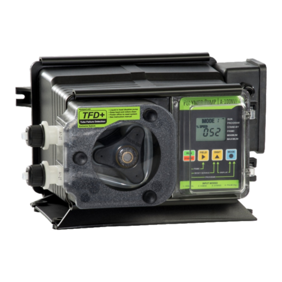
- Page 1 ® MODELS A-100NVP & A-100NFP Variable Speed Peristaltic Injector Pump Operating Manual 5300 Business Drive Huntington Beach, CA 92649 Phone: 714-893-8529 FAX: 714-894-9492 E mail: sales@blue-white.com or techsupport@blue-white.com Website: www.blue-white.com...
-
Page 2: Table Of Contents
A-100N Page 2 TABLE OF CONTENTS 1 ..Introduction..................2 2 ..Specifications ..................3 3 ..Features....................3 4 ..Unpacking....................3 5 ..Installation .. -
Page 3: Specifications
A-100N Page 3 2.0 Specifications 65 psig / 4.5 bar (most models) Maximum Working Pressure Maximum Fluid Temperature 130 F / 54 C 14 to 110 F / -10 to 43 C Ambient Temperature Range Continuous Duty Cycle Adjustment Range 14 &... -
Page 4: Installation
A-100N Page 4 5.0 Installation CAUTION: Proper eye and skin protection must be worn when installing and servicing the pump. Note: All diagrams are strictly for guideline purposes only. Always consult an expert before installing the pump into specialized systems. The pump should be serviced by qualified persons only. -
Page 5: Input Power Connections (A-100Nvp)
A-100N Page 5 TYPICAL INSTALLATION Injection / Check valve with 1/4” and 1/2” male pipe threads. Mount in upward position Discharge to prevent trapped gasses Tube in the injection fitting. Wall or shelf mount MODE % SPEED 1000 ALARM SERVICE away from the top of the solution tank. -
Page 6: External Input/Output Signal Connections (A-100Nvp)
A-100N Page 6 5.2.1 External Input Signal Connections (A-100NVP) The pump will accept any one of three different types of external input signals; 4-20 mA , 0-10 VDC, or pulse frequency (500 Hz maximum). The 4-20mA and 0-10 VDC loops must be powered. Two types of frequency inputs, AC sine waves (magnetic coils type outputs) and Digital Square waves (Hall Effect signals, contact closures), are acceptable. - Page 7 A-100N Page 7 OPEN COLLECTOR MOTOR ON OUTPUT SCHEMATICS (A-100NVP) OUTPUT SCHEMATIC TYPICAL EXAMPLE (+) 6 to 30 Vdc Relay 2K ohm resistor typical 50mA max coil 2K ohm (+) Vdc (+) 24Vdc LOAD 50mA (-) Vdc (-) 24Vdc (-) DC Ground BROWN BLACK A-100N...
-
Page 8: Input Power Connections (A-100Nfp)
A-100N Page 8 5.3 Input Power Connections (A-100NFP) WARNING: Risk of electric shock. Be certain to connect the pump to the proper supply voltage. Using the incorrect voltage will damage the pump and may result in injury. The voltage requirement is printed on the pump serial label. The pump is supplied with either a ground wire conductor and a grounding type attachment plug (power cord) or a junction box for field wiring. - Page 9 A-100N Page 9 WIRING DIAGRAM (A-100NFP) NOTCH LOCATION INDICATES INPUT POWER REQUIREMENT SPEED ADJUSTMENT 108/130 VAC POTENTIOMETER 208/240 VAC COMMON WHITE YELLOW INPUT GROUND POWER BLACK SWITCH - + - + MA AL PURPLE BLACK MOTOR (-) Vdc (+) 90 Vdc...
-
Page 10: Optional Output Signal Connection (A-100Nfp)
A-100N Page 10 5.3.1 Optional output signal connection (A-100NFP) - The pump includes three optional external signal connections: ! FVS - FLOW VERIFICATION SENSOR INPUT Accepts a pulse signal from an optional sensor confirming that fluid is passing through the pump. Triggers and alarm output if fluid is not detected. ! AL - ALARM OPEN COLLECTOR OUTPUT The output (purple wire) sinks to DC ground when an alarm condition exists. - Page 11 A-100N Page 11 CIRCUIT BOARD SIGNAL CONNECTION (A-100NFP) FVS - FLOW VERIFICATION SENSOR INPUT 120 VAC 230VAC LOAD - + - + MA AL AL - OPEN COLLECTOR ALARM OUTPUT MA - OPEN COLLECTOR MOTOR ACTIVE OUTPUT...
-
Page 12: How To Install The Tubing And Fittings
A-100N Page 12 5.4 How To Install the Tubing and Fittings CAUTION: Proper eye and skin protection must be worn when installing and servicing the pump. ! Inlet Tubing - Locate the inlet fitting of the Pump Tube. Remove the tube nut. -
Page 13: How To Operate The A-100N Polymer Pump
A-100N Page 13 6.0 How To Operate The A-100N 6.1 Description of Pump Output (A-100NVP) Adjustment Controls - Open the control panel MODE door by sliding the upper and lower slide clamps to % SPEED 1000 the left. ALARM SERVICE ! RUN/STANDBY Button - 4 Press to start and stop the pump. -
Page 14: Mode 1 - Manually Adjusting The Output
A-100N Page 14 6.1.1 OPERATING MODE 1 - Output adjusted manually - In this mode, the pump’s motor speed is adjusted manually using the front panel touch pad. The motor speed can be adjusted from 5-100%. To adjust the speed: RUN MODE 1 4 Set the pump for mode 1. - Page 15 A-100N Page 15 input value. 4 Enter the programming mode. At the same time, PROGRAM MODE 2 press the RUN/STANDBY and MODE buttons. A % speed at the minimum input blinking ARROW will point to the word PROGRAM MODE PROGRAM % SPEED indicating the program mode is activated.
-
Page 16: Mode 3 - 0-10 Vdc Input
A-100N Page 16 Repeat until all digits are programmed. Press the mode button. Programming is complete. To exit the programming mode, press the RUN/STANDBY button and the MODE button at the same time. The PROGRAM arrow will disappear. MODE 2 PROGRAMMING EXAMPLES Example 4 Example 4 Example 4... - Page 17 A-100N Page 17 4 Enter the motor speed at the minimum VDC input signal value. Press the FIELD button to select the digit to program. The digit will blink when selected. 4 Press the DIGIT button to change the selected digit. 4 Repeat until all digits are programmed.
-
Page 18: Mode 4 - Frequency/Pulse (Hz) Input
A-100N Page 18 6.1.4 OPERATING MODE 4 - Output adjusted by frequency (Hz) input signal In this mode, the pump’s motor speed is adjusted automatically based on the frequency (Hz) of the input signal (500 Hz max). Any motor speed can be assigned to either the minimum or maximum Hz input signals. - Page 19 A-100N Page 19 currently programmed maximum motor speed value is shown on the 3-DIGIT LCD. 4 Enter the motor speed at the maximum Hz input PROGRAM MODE 4 signal value. Press the FIELD button to select the % speed at the maximum input digit to program.
-
Page 20: How To Adjust The Output (A-100Nfp)
! Slide the slide clamps to the left only far enough to open the control panel door. ! Turn the adjustment knob to the desired percent- age of speed. A-100N A-100N A-100N BLUE-WHITE INDUSTRIES BLUE-WHITE INDUSTRIES BLUE-WHITE INDUSTRIES SLIDE CLAMP... -
Page 21: Alarms
A-100N Page 21 7.0 ALARMS 7.1 TFD+ - Enhanced Tube Failure Detection system - The A- 100N Polymer Pump is equipped with an Enahnced Tube Failure Detection System which is designed to stop the pump and provide a contact closure output in the event the pump tube should rupture and fluid enters the pump head. -
Page 22: Fvs - Flow Verification System
A-100N Page 22 7.2 FVS - Flow Verification System - (sensor sold separately) A-100N Polymer Pump is equipped with a Flow Verification System which is designed to stop the pump and provide a contact closure output in the event the sensor does not detect chemical during pump operation. This could indicate a clogged injection fitting, empty chemical solution tank, worn pump tube, loose tubing connection, etc. -
Page 23: How To Maintain The Pump
A-100N Page 23 8.0 How to Maintain the Pump CAUTION: Proper eye and skin protection must be worn when installing and servicing the pump. 8.1 Routine Inspection and Maintenance The pump requires very little maintenance. However, the pump and all accessories should be checked weekly. -
Page 24: How To Replace The Pump Tube
A-100N Page 24 How to Replace the Pump Tube The pump tube assembly will eventually break if not replaced. The tube has been designed for a minimum service life of 500 hours. However, the life of the tube is affected by many factors such as the type of chemical being pumped, the amount of back pressure, the motor RPM, temperature and others. -
Page 25: Replacement Pump Tube Part Numbers
A-100N Page 25 REPLACEMENT PUMP TUBE AND ROLLER ASSEMBLY PART NUMBERS Model Pump Tube Roller Assembly Number Part Number Part Number A1N0*V-1T-P A1-1T 71000-350 A1N1*V-1T-P A1-1T 71000-350 A1N3*V-1T-P A1-1T 71000-350 A1N3*V-2T-P A1-2T 71000-350 A1N2*V-3T-P A1-3T 71000-350 A1N3*V-3T-P A1-3T 71000-350 Model Pump Tube Roller Assembly Number... -
Page 26: Replacement Parts Drawing (A-100Nvp)
A-100N Page 26 REPLACEMENT PARTS DRAWING (A-100NVP) A1-4T A1-4T... -
Page 27: Replacement Parts List (A-100Nvp)
A-100N Page 26 REPLACEMENT PARTS DRAWING (A-100NVP) -
Page 28: Replacement Part Drawing (A-100Nfp)
A-100N Page 28 REPLACEMENT PARTS DRAWING (A-100NFP) A1-4T A1-4T... -
Page 29: Replacement Parts List (A-100Nfp)
A-100N Page 29 REPLACEMENT PARTS DRAWING (A-100NFP) -
Page 30: Warranty Information
Page 30 Limited Warranty Your Blue-White product is a quality product and is warranted for a specific time from date of purchase (proof of purchase is required). The product will be repaired or replaced at our discretion. Failure must have occurred due to defect in material or workmanship and not as a result of operation of the product other than in normal operation as defined in the product manual. - Page 31 Chemical Resistance Warning Blue-White offers a wide variety of wetted parts. Purchasers, installers, and operators of Blue-White products must be well informed and aware of the precautions to be taken when injecting or measuring various chemicals, especially those considered to be irritants, contaminants or hazardous.
- Page 32 5300 Business Drive Huntington Beach, CA 92649 Phone: 714-893-8529 FAX: 714-894-9492 E mail: sales@blue-white.com or customerservice@blue-white.com Website: www.blue-white.com # 80000-587 Rev. 3 20230501...
Need help?
Do you have a question about the FLEXFLO A-100NVP and is the answer not in the manual?
Questions and answers