Table of Contents
Advertisement
CERTIFIED FINAL DOCUMENT
R
FLEX-PRO
Peristaltic Metering Pump
®
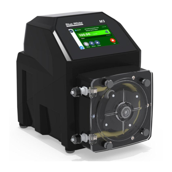
PROSERIES-M
M-3 and M-4
Operating and Maintenance Manual
Exclusive:
TF D
system
Tube Failure Detection
Patent No. 7,001,153 & 7,284,964
ProSeries
R
ProSeries
TM
5
Protected by Patents: 8,215,931;
F IVE-YEAR
by Blue-White Ind.
7,001,153; 7,284,964; 4,496,295
WARRANTY
and other patents pending
5300 Business Drive, Huntington Beach, CA 92649
USA
Phone: 714-893-8529
FAX: 714-894-9492
E mail: sales@blue-white.com or techsupport@blue-white.com
URL: www.Blue-White.com
Advertisement
Table of Contents

Subscribe to Our Youtube Channel
Related Manuals for Blue-White FLEX-PRO PROSERIES-M Flex-A-Prene M-3


Summary of Contents for Blue-White FLEX-PRO PROSERIES-M Flex-A-Prene M-3
- Page 1 Patent No. 7,001,153 & 7,284,964 ProSeries ProSeries Protected by Patents: 8,215,931; F IVE-YEAR by Blue-White Ind. 7,001,153; 7,284,964; 4,496,295 WARRANTY and other patents pending 5300 Business Drive, Huntington Beach, CA 92649 Phone: 714-893-8529 FAX: 714-894-9492 E mail: sales@blue-white.com or techsupport@blue-white.com URL: www.Blue-White.com...
-
Page 2: Table Of Contents
Please Note: Your new pump has been pressure tested at the factory with clean water before shipping. You may notice trace amounts of clean water in the pre-installed tube assembly. This is part of our stringent quality assur- ance program at Blue-White Industries. -
Page 3: Available Models
Page 3 Flex-Pro Available Models M-3 Model Numbers Output Range Speed Pressure Temperature ® Flex-A-Prene M-3 Tube Pumps Listed under NSF Std. 61 Meets FDA criteria for food | Excellent chemical resistance | CIP | SIP ML/MIN PSI (bar) F (C) 115V AC 230V AC 220V AC... -
Page 4: Specifications
Page 4 Flex-Pro Specifications Approximate shipping wt: Maximum working pressure (excluding pump tubes): M-3 models: 33 lb. (15.0 Kg) 125 psig (8.6 bar) M-4 models: 58 lb. (26.3 Kg) Note: see individual pump tube assembly maximum pressure ratings. Maximum Fluid temperature (excluding pump tubes): Motor speed adjustment range 185 F (85 C) 10,000:1 (0.01% - 100% motor speed) -
Page 5: Features
Inject at maximum pressure in either direction (clockwise or counter clockwise). Compatible with Blue-White’s output Flow Verification Sensor (FVS) system. Enclosure Rating: NEMA 4X: Constructed for either indoor or outdoor use to provide a degree of protection to personnel against incidental contact with enclosed equipment;... -
Page 6: Installation
Page 6 Flex-Pro Installation CAUTION Risk of chemical overdose. Be certain pump does not overdose chemical during backwash and periods of no flow in circulation system. CAUTION Always wear protective clothing, face shield, safety glasses and gloves when working on or near your metering pump. -
Page 7: Mounting Dimensions
Page 7 Flex-Pro Mounting Dimensions 18.63” 12.13" (47.3cm) 30.8cm) 14.2" (36.1cm) 6.0" (15.2cm) Right View Front View 11.0" (27.9cm) 13.63” (34.6cm) Mounting Hole Spacings (for standard and extended type brackets) 27.3 36.1 10-3/4” 14-1/4” 20.6 30.8 8-1/8” 12-1/8” 2.5” (6.35 cm) 15-1/4”... -
Page 8: Input Power Connections
Page 8 Flex-Pro 2.3 Input Power Connections WARNING Risk of electric shock – cord connected models are supplied with a grounding conductor and grounding-type attachment plug. To reduce risk of electric shock, be certain that it is connected only to a properly grounded, grounding-type receptacle. WARNING Electrical connections and grounding (earthing) must conform to local wiring codes. -
Page 9: Wiring Terminals And I/O Schematics
0-10 (+) GND (-) TRANSMITTER (-) NEGATIVE +15 VDC 4-20 (+) SOURCE INPUT: BLACK (-) (+) POSITIVE FVS SYSTEM BARE BLUE-WHITE (FLOW VERIFICATION SIGNAL FVS SENSOR SENSOR) FV SENSOR ONLY (-) NEGATIVE RED (+) INPUT: NEGATIVE (-) (+) POSITIVE FVS SYSTEM... -
Page 10: How To Operate Flex-Pro
Page 10 Flex-Pro How To Operate Flex-Pro Flex-Pro M Series, Control Panel - Button Operation Press and hold MODE for Setup ProSeries by Blue-White Ind. Peristaltic Metering Pump TUBE TUBE TUBE PERISTALTIC INFO INFO INFO METERING PUMP Press and release to select a Run Mode. -
Page 11: Menu Navigation
Page 11 Flex-Pro 3.1 Menu Navigation – Sample screen shots – - Menu Use MENU button to enter menu for setting up pump. + Configuration + Input Setup Use UP or DOWN arrows to navigate through menu. + Output Setup + Power Fail option Active option appears on pump display in inverse... -
Page 12: Configuration Menu
Page 12 Flex-Pro 3.2 Configuration Menu Below is the menu structure for the Configuration screens. - Menu + Configuration + Input Setup + Output Setup + Power Fail option <- Esc - Configuration - Configuration - Configuration - Configuration + Display Language + Display Language + Display Language + Display Language... -
Page 13: Display Rate (Units Of Measure)
Page 13 Flex-Pro 3.2.2 Display Rate (Units of Measure) - Configuration + Display Language By default, the pump will display %Speed (motor speed) and RPM. It is + Set Password recommended you select an additional Display Rate. After selecting another + Display Rate Display Rate (such as ML/Min), the pump display may be toggled through + Reset to Factory Defaults... -
Page 14: Input Setup
(select one) + Set TFD Set Flow Verification time delay. Use this + Remote/Local + Set Rev Alarm feature if you are using a Blue-White <- Esc flow verification sensor to monitor flow - Input Setup - Set FVS output. Default setting is OFF. -
Page 15: Max Rpm Cut-Off
Page 15 Flex-Pro - Input Setup 4.1 Max RPM cut-off + Max RPM cut-off + Max Flowrate The maximum motor RPM can be limited to reduce the possibility of overfeeding + Input Modes chemical into the system. Note that the pump’s display will still reference values + Contact Input calculated from the 100% motor speed MAX Flowrate value (see section 4.2). -
Page 16: Input Setup (Operating Mode Configuration)
Page 16 Flex-Pro 4.3 Input Setup (operating mode configuration) Run Mode (operating Input Mode) MODE button also serves as a Tip! shortcut button. Press and Hold MODE button to enter the programming menu for the MODE current Run Mode. After programming the Run Mode, press ENTER to save changes. -
Page 17: Ma Input
Page 17 Flex-Pro 4.3.2 4 - 20 mA Input - 4-20 mA Input Min mA Signal: 4.00 Used to remotely control the pump with an incoming 4-20 mA signal. Input Min. mA signal Input. Default settings: 4 mA = 0% motor speed Press ENTER to set. -
Page 18: Vdc Input
Page 18 Flex-Pro 4.3.3 0 - 10 VDC Input (Volt DC) - 0-10 VDC Input Min VDC Signal: 0.00 Used to remotely control the pump with an incoming 0-10 VDC signal. Input Min. VDC Default settings: 0 VDC = 0% motor speed Press ENTER to set. -
Page 19: Frequency Input (Hz)
Page 19 Flex-Pro 4.3.4 Frequency Input (Hz) - Frequency Input Min Freq. Signal: Used to remotely control the pump with an incoming high speed frequency signal. Typically used with flow meters or other external devices. Input Min. Freq. (Hz) Press ENTER to set. Default settings: 0 Frequency (Hz) = 0% motor speed 1000 Frequency (Hz) = 100% motor speed... -
Page 20: Pulse Batch (Low Speed Batch)
Page 20 Flex-Pro 4.3.5 Pulse Batch (low speed pulse) - Pulse Batch Input Pulse Num: Used to remotely control the pump with an incoming pulse signal. Can be used with an external foot pedal, a water meter, a PLC, contact closure, or other low Pulse num. -
Page 21: Manual Cycle Adjust (Repeating Cycle Timer)
Page 21 Flex-Pro - Cycle Adjust 4.3.6 Manual Cycle Adjust (repeating cycle timer) Input Flow Rate: 50.0 Used to operate the pump at a pre-selected motor speed for a specified run time. This cycle will repeat itself using a repeating cycle timer. Input Flow Rate. -
Page 22: Dispensing
Page 22 Flex-Pro 4.3.7 Dispensing - Dispensing Volume to Dispense: 000010.0 Configure any dispensing amount or sample size and the pump will repeat it on command by pressing the START button. Great for accurate single shot dispens- Input mL to dispense. ing of a pre-configured volume. -
Page 23: Manual Dosing
Page 23 Flex-Pro 4.3.8 Manual Dosing - Manual Dosing Dose Concentration: Used to configure Parts Per Million dosing to a system. This method can be 2.5% used if treated fluid volume is a fixed amount (in Liters Per Minute). If treated % of concentration. -
Page 24: Proportional Dosing
Example #2, Paddlewheel flow meter Paddlewheel Injection Injection Flow Sensor / Meter Point Point S3 Series | Hybrid Ultrasonic Flowmeter NEMA 4X IP 66 Ultrasonic Flow Meter Doppler / ProSeries Transit Time by Blue-White Ind. Industries, Ltd. Discharge Line Discharge Line... -
Page 25: Contact Closure Input (Remote Start/Stop)
Page 25 Flex-Pro 4.4 Contact Closure Input (Remote Start/Stop) - Menu + Configuration + Input Setup Used to remotely start and stop the pump using a close=stop or open=stop + Pump Output signal. If the pump must start when the loop is open, then select “Close: Stop <- Esc Pump”... -
Page 26: Set Fvs (Flow Verification System)
+ Operating Input Modes when pump head rotor is turning, the pump will go into an alarm mode and + Contact Closure Input stop. Blue-White offers a flow verification sensor that easily attaches to the inlet + Set FVS fitting of the pump. -
Page 27: Tfd (Tube Failure Detection)
Page 27 Flex-Pro 4.6 TFD (Tube Failure Detection) Flex-Pro is equipped with a Tube Failure Detection System which is designed to stop the pump and provide an output alarm (see Output menu) in the event pump the tube should rupture and chemical enters the pump head. At the default adjustment setting of 75%, the pump will detect a chemical with a conductivity reading greater than 500 microsiemens. -
Page 28: Remote/Local Control
Page 28 Flex-Pro - Input Setup 4.7 Remote/Local Control + Input Modes + Contact Input The Flex-Pro can be configured for Remote control only, Local control only, or + Set FVS either (disabled). + Set TFD + Remote/Local + Set Rev Alarm When set for Remote control only, all touch pad buttons except the menu button are <- Esc disabled. -
Page 29: Output Setup (Alarm Relays & Output Signal Signals)
Page 29 Flex-Pro 5.0 Output Setup (alarm relays) - Menu + Configuration + Input Setup Note: + Output Setup Contact #1 shown only. Contact #2, and + Power Fail option Contact #3 use the same menu items. <- Esc Output - Signal Output - Assign Relay Output - Contact Closure #1... -
Page 30: Signal Output
Page 30 Flex-Pro Signal Output Sends a configurable 4 - 20 mA or frequency (Hz) signal to another pump or external device. This feature can be used to control other pumps (in sync / proportionally), data logging systems, and other external devices for plant automation. -
Page 31: Pump Maintenance
Page 31 Flex-Pro Pump Maintenance CAUTION Always wear protective clothing, face shield, safety glasses and gloves when working on or near your metering pump. Additional precautions should be taken depending on solution being pumped. Refer to MSDS precautions from your solution supplier. Routine Inspection and Maintenance The pump requires very little maintenance. -
Page 32: Tube Replacement
Page 32 Flex-Pro 6.4 Tube Replacement CAUTION Prior to service, pump clean water through the pump and suction / discharge line to remove chemical. CAUTION Always wear protective clothing, face shield, safety glasses and gloves when working on or near your metering pump. Additional precautions should be taken depending on solution being pumped. - Page 33 Page 33 Flex-Pro Insert suction fitting into pump head. Remove your fingers from Introduce tubing into pump head while the rotor is rotating. Avoid pump head. Start pump by pressing START button. Grab hold of using fingers to guide the tubing. Stop pump at anytime by Tube Installation Tool and use it to leverage tubing into pump head.
-
Page 34: Replacement Parts List
Page 34 Flex-Pro 6.5 Replacement Parts List Replacement Parts List Peristaltic Metering Pump Item Description Part Number Spacer, Back 90011-184 Roller Assembly Complete (Rotor), For ND Tubes Tubing in this group are A3-SND-R interchangeable with ® A3-SND-T Tube Assembly, 3/8” OD tube compression fitting, Flex-A-Prene ND (.075 ID) single roller assembly (rotor). - Page 35 Page 35 Flex-Pro Replacement Parts List Peristaltic Metering Pump Item Part Number Description Spacer, two spacers required, A4 (replaces 90011-184) 90011-217 Tubing in this group Roller Assy Complete (A4 Rotor), For NH, NJ, NK, NHH Tubes A4-MNH-R are interchangeable ® Tube Assembly, 1/2”...
-
Page 36: Tubing Data
Page 36 Flex-Pro 7.1 Output Versus Fluid Viscosity Flow Rate (ml/min) Flow Rate (ml/min) Flow Rate (ml/min) Flow Rate (ml/min) - Page 37 Page 37 Flex-Pro Flow Rate (ml/min) Flow Rate (ml/min) Flow Rate (ml/min) Flow Rate (ml/min)
- Page 38 Page 38 Flex-Pro Intentionally Left Blank...
- Page 39 Page 39 Flex-Pro Intentionally Left Blank...
- Page 40 Warranty status is determined by the pump's serial label and the sales invoice or receipt. The serial label must be on the pump and legible. The warranty status of the pump will be verified by Blue-White or a factory authorized service center.
Need help?
Do you have a question about the FLEX-PRO PROSERIES-M Flex-A-Prene M-3 and is the answer not in the manual?
Questions and answers