Advertisement
Quick Links
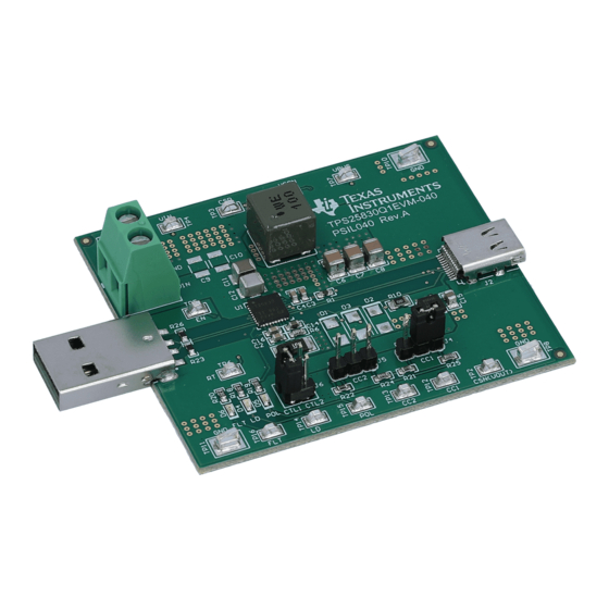
This user's guide describes the TPS25830-Q1 evaluation module (TPS25830Q1EVM-040). This document
contains the EVM schematics, EVM configuration, bill of materials(BOM), board layout drawing and
assembly drawing.
...................................................................................................................
1
.....................................................................................................................
2
3
4
Board Layout
5
Bill of Materials
1
TPS25830Q1EVM-040 Schematic
2
3
4
5
6
7
Top Layer Layout
8
Middle Layer 1 Layout
9
Middle Layer 2 Layout
10
Bottom Layer Layout
...................................................................................................................
1
Connectors
.......................................................................................................................
2
Jumpers
............................................................................................................................
3
LED
....................................................................................................................
4
Test Points
5
Bill of Materials
Trademarks
USB Type-C is a trademark of USB Implementers Forum.
All other trademarks are the property of their respective owners.
SLVUBE2A - April 2018 - Revised May 2019
Submit Documentation Feedback
TPS25830-Q1 Evaluation Module
...................................................................................
.................................................................................................................
.............................................................................................................
........................................................................................
.........................................................................................................
.....................................................................................................
...........................................................................................................
.......................................................................................................
...........................................................................................................
......................................................................................................
......................................................................................................
.......................................................................................................
.............................................................................................................
Copyright © 2018-2019, Texas Instruments Incorporated
SLVUBE2A - April 2018 - Revised May 2019
Contents
List of Figures
.......................................................................
List of Tables
User's Guide
TPS25830-Q1 Evaluation Module
2
3
4
6
10
3
5
6
6
6
7
7
8
8
9
4
4
4
4
10
1
Advertisement

Related Manuals for Texas Instruments TPS25830Q1EVM-040


Summary of Contents for Texas Instruments TPS25830Q1EVM-040
-
Page 1: Table Of Contents
User's Guide SLVUBE2A – April 2018 – Revised May 2019 TPS25830-Q1 Evaluation Module This user's guide describes the TPS25830-Q1 evaluation module (TPS25830Q1EVM-040). This document contains the EVM schematics, EVM configuration, bill of materials(BOM), board layout drawing and assembly drawing. Contents ........................ -
Page 2: Introduction
Introduction The TPS25830Q1EVM-040 is an evaluation module (EVM) for TI's TPS25830-Q1 USB Type-C™ and BC1.2 5-V, 3.5-A output and 36-V input synchronous buck with cable compensation. The EVM operates over a range from 6 V to 36 V and provides USB Type-C connectors to evaluate BC1.2, USB Type-C charging and USB2.0 data communication functions. -
Page 3: Schematic
AGND PGND /LD_DET /POL /FAULT Shield Shield Shield Shield AGND AGND TP14 TP15 TP16 PGND PGND Figure 1. TPS25830Q1EVM-040 Schematic SLVUBE2A – April 2018 – Revised May 2019 TPS25830-Q1 Evaluation Module Submit Documentation Feedback Copyright © 2018–2019, Texas Instruments Incorporated... -
Page 4: General Configuration And Description
General Configuration and Description www.ti.com General Configuration and Description This section describes the connectors, jumpers, LED and test points on the EVM and how to properly connect, set up and use the TPS25830Q1EVM-040. Physical Access Table 1 lists the TPS25830Q1EVM-040 connector functionality,... -
Page 5: Evm Setup For Charging Usb Type-C™ Device
Connect USB Type-C device to J2 connector. Shunts do not need to be installed on J4 or J5. 13.5 V, Type-C ± phone Figure 2. EVM Setup for Charging USB Type-C™ Device SLVUBE2A – April 2018 – Revised May 2019 TPS25830-Q1 Evaluation Module Submit Documentation Feedback Copyright © 2018–2019, Texas Instruments Incorporated... -
Page 6: Top Side Assembly
Figure 7 Figure 10 show the layout of the EVM. Figure 3. Top Side Assembly Figure 4. Bottom Side Assembly TPS25830-Q1 Evaluation Module SLVUBE2A – April 2018 – Revised May 2019 Submit Documentation Feedback Copyright © 2018–2019, Texas Instruments Incorporated... -
Page 7: Top Side 3D View
Board Layout www.ti.com Figure 5. Top Side 3D View Figure 6. Bottom Side 3D View SLVUBE2A – April 2018 – Revised May 2019 TPS25830-Q1 Evaluation Module Submit Documentation Feedback Copyright © 2018–2019, Texas Instruments Incorporated... - Page 8 Board Layout www.ti.com Figure 7. Top Layer Layout Figure 8. Middle Layer 1 Layout TPS25830-Q1 Evaluation Module SLVUBE2A – April 2018 – Revised May 2019 Submit Documentation Feedback Copyright © 2018–2019, Texas Instruments Incorporated...
- Page 9 Board Layout www.ti.com Figure 9. Middle Layer 2 Layout Figure 10. Bottom Layer Layout SLVUBE2A – April 2018 – Revised May 2019 TPS25830-Q1 Evaluation Module Submit Documentation Feedback Copyright © 2018–2019, Texas Instruments Incorporated...
- Page 10 RES, 5.1 k, 5%, 0.1 W, AEC-Q200 Grade 0, 0603 0603 CRCW06035K10JNEA Vishay-Dale SH-J1, SH-J2 Shunt, 2.54 mm, Gold, Blue Shunt, 2.54 mm, Blue 60900213621 Wurth Elektronik TPS25830-Q1 Evaluation Module SLVUBE2A – April 2018 – Revised May 2019 Submit Documentation Feedback Copyright © 2018–2019, Texas Instruments Incorporated...
- Page 11 RES, 0, 1%, 0.1 W, AEC-Q200 Grade 0, 0603 0603 RMCF0603ZT0R00 Stackpole Electronics R8, R12 RES, 0, 1%, 0.5 W, 1206 1206 5108 Keystone SLVUBE2A – April 2018 – Revised May 2019 TPS25830-Q1 Evaluation Module Submit Documentation Feedback Copyright © 2018–2019, Texas Instruments Incorporated...
- Page 12 Revision History www.ti.com Revision History Changes from Original (April 2018) to A Revision ......................Page ........................• First public release Revision History SLVUBE2A – April 2018 – Revised May 2019 Submit Documentation Feedback Copyright © 2018–2019, Texas Instruments Incorporated...
- Page 13 STANDARD TERMS FOR EVALUATION MODULES Delivery: TI delivers TI evaluation boards, kits, or modules, including any accompanying demonstration software, components, and/or documentation which may be provided together or separately (collectively, an “EVM” or “EVMs”) to the User (“User”) in accordance with the terms set forth herein.
- Page 14 www.ti.com Regulatory Notices: 3.1 United States 3.1.1 Notice applicable to EVMs not FCC-Approved: FCC NOTICE: This kit is designed to allow product developers to evaluate electronic components, circuitry, or software associated with the kit to determine whether to incorporate such items in a finished product and software developers to write software applications for use with the end product.
- Page 15 www.ti.com Concernant les EVMs avec antennes détachables Conformément à la réglementation d'Industrie Canada, le présent émetteur radio peut fonctionner avec une antenne d'un type et d'un gain maximal (ou inférieur) approuvé pour l'émetteur par Industrie Canada. Dans le but de réduire les risques de brouillage radioélectrique à...
- Page 16 www.ti.com EVM Use Restrictions and Warnings: 4.1 EVMS ARE NOT FOR USE IN FUNCTIONAL SAFETY AND/OR SAFETY CRITICAL EVALUATIONS, INCLUDING BUT NOT LIMITED TO EVALUATIONS OF LIFE SUPPORT APPLICATIONS. 4.2 User must read and apply the user guide and other available documentation provided by TI regarding the EVM prior to handling or using the EVM, including without limitation any warning or restriction notices.
- Page 17 Notwithstanding the foregoing, any judgment may be enforced in any United States or foreign court, and TI may seek injunctive relief in any United States or foreign court. Mailing Address: Texas Instruments, Post Office Box 655303, Dallas, Texas 75265 Copyright © 2019, Texas Instruments Incorporated...
- Page 18 TI products. TI’s provision of these resources does not expand or otherwise alter TI’s applicable warranties or warranty disclaimers for TI products. Mailing Address: Texas Instruments, Post Office Box 655303, Dallas, Texas 75265 Copyright © 2019, Texas Instruments Incorporated...
Need help?
Do you have a question about the TPS25830Q1EVM-040 and is the answer not in the manual?
Questions and answers