Table of Contents
Advertisement
Quick Links
Advertisement
Table of Contents

Related Manuals for Honda FQ650


Summary of Contents for Honda FQ650
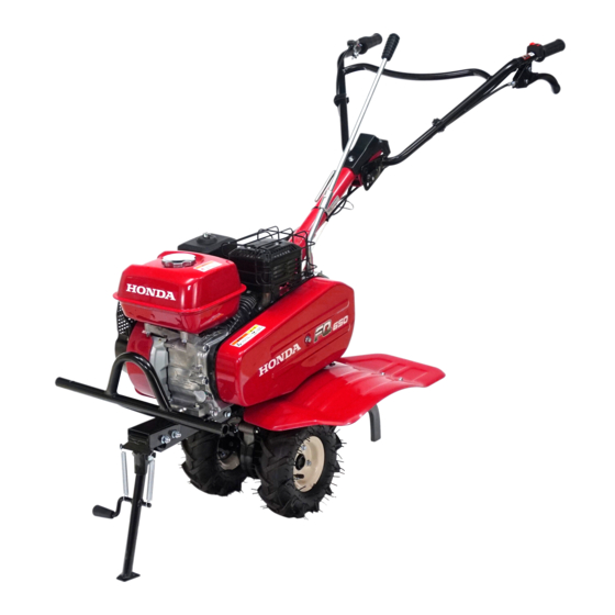
- Page 1 TILLER FQ650 OWNER'S MANUAL...
- Page 2 The information and specifications included in this publication were in effect at the time of approval for printing. Honda Motor Co., Ltd. reserves the right, however, to discontinue or change specifications or design at any time...
- Page 3 INTRODUCTION Congratulations on your selection of a Honda tiller. We are certain you will be pleased with your purchase of one of the finest tillers on the market. We want to help you get the best results from your new tiller and to operate it safely.
- Page 4 INTRODUCTION A FEW WORDS ABOUT SAFETY Your safety and the safety of others are very important. And using this tiller safely is an important responsibility. To help you make informed decisions about safety, we have provided operating procedures and other information on labels and in this manual. This information alerts you to potential hazards that could hurt you or others.
-
Page 5: Table Of Contents
CONTENTS TILLER SAFETY ....................5 IMPORTANT SAFETY INFORMATION................5 SAFETY LABEL LOCATIONS....................9 CONTROLS....................... 11 COMPONENT & CONTROL LOCATIONS ................11 CONTROLS..........................13 Fuel Valve..........................13 Choke Lever ........................13 Engine Switch........................13 Starter Grip.........................14 Throttle Lever........................14 Handlebar Height Adjuster ..................14 Clutch Lever........................15 Gearshift Lever........................15 Drag Bar..........................15 Hitch Box..........................16 BEFORE OPERATION.................. - Page 6 CONTENTS SERVICING YOUR TILLER (continued) SPARK PLUG SERVICE ......................47 THROTTLE CABLE ADJUSTMENT ..................49 TINE REPLACEMENT (Rotor: Standard equipment for types)........50 TIRE PRESSURE CHECK ......................52 TINES AND FASTENERS CHECK ..................53 RECOIL STARTER COVER CHECK AND CLEANING............54 HANDLEBAR HEIGHT ADJUSTER TIGHTNESS CHECK ..........55 STORAGE ......................
-
Page 7: Tiller Safety
TILLER SAFETY IMPORTANT SAFETY INFORMATION Honda tillers are designed to cultivate earth outdoors. Other uses can result in injury to the operator or damage to the tiller and other property. Most accidents can be prevented if you follow all instructions in this manual and on the tiller. - Page 8 TILLER SAFETY Carbon Monoxide Hazards Your tiller’s exhaust contains poisonous carbon monoxide gas, which you cannot see or smell. Breathing carbon monoxide can KILL YOU IN MINUTES. For your safety: • Do not start or operate the engine in any closed or partially enclosed area, such as a garage.
- Page 9 TILLER SAFETY Avoid Rotating Tines Rotating tines can cause serious cuts and even amputate body parts. Keep away from the tine area whenever the engine is running. If you need to work around the tines to clear an object accumulation or for any other reason, always shut off the engine.
- Page 10 Tools and Attachments To install a tool or attachment on the tiller, follow the instructions furnished with the tool or attachment. Ask your Honda dealer for advice if you encouter any problem or difficulty in installing a tool or attachment.
-
Page 11: Safety Label Locations
TILLER SAFETY SAFETY LABEL LOCATIONS These labels warn you of potential hazards that can cause serious injury. Read them carefully. If a label comes off or becomes hard to read, contact your servicing dealer for a replacement. - Page 12 TILLER SAFETY...
-
Page 13: Controls
CONTROLS COMPONENT & CONTROL LOCATIONS HANDLEBAR GEARSHIFT LEVER AIR CLEANER FUEL TANK CAP MUFFLER V-BELT COVER FENDER FRONT GUARD TIRE ENGINE OIL OIL FILLER CAP DRAIN PLUG FRONT STAND... - Page 14 CONTROLS ENGINE SWITCH THROTTLE LEVER SPARK PLUG CAP CHOKE LEVER CLUTCH LEVER HANDLEBAR HEIGHT ADJUSTER STARTER GRIP DRAG BAR FUEL VALVE LEVER TRANSMISSION OIL FILLER CAP...
-
Page 15: Controls
CONTROLS CONTROLS Fuel Valve The fuel valve opens and closes the connection between the fuel tank and FUEL VALVE LEVER the carburetor. The fuel valve lever must be in the ON position for the engine to run. After stopping the engine, move the fuel valve lever to the OFF position. -
Page 16: Starter Grip
CONTROLS Starter Grip Pulling the starter grip operates the recoil starter to crank the engine. STARTER GRIP Throttle Lever ADJUSTING SCREW The throttle lever controls engine speed. Moving the throttle lever in the THROTTLE LEVER directions shown makes the engine run faster or slower. -
Page 17: Clutch Lever
CONTROLS Clutch Lever The clutch lever engages and disengages the transmission that ENGAGED drives the tines. DISENGAGED CLUTCH LEVER Gearshift Lever GEARSHIFT LEVER The transmission offers a choice of two forward speeds, neutral, and one reverse speed. Shift lever positions are indicated on the gearshift lever bracket. -
Page 18: Hitch Box
CONTROLS Hitch Box Use a hitch pin as shown below to attach the drag bar or any other attachments to the hitch box. HITCH PIN HITCH BOX LOCK PIN Front stand The front stand is used to park the tiller. When tilling or moving the tiller, fold the front stand. -
Page 19: Before Operation
BEFORE OPERATION ARE YOU READY TO GET STARTED? Your safety is your responsibility. A little time spent in preparation will significantly reduce your risk of injury. Knowledge Read and understand this manual. Know what the controls do and how to operate them. -
Page 20: Check The Engine
• Start the engine. Check for abnormal sounds. (See pages 20 through 22 for starting procedure.) • Check that the engine stops securely by operating the engine switch. (See page 35 for stopping procedure.) • If you notice any other abnormal symptoms, consult with your authorized Honda dealer promptly. -
Page 21: Operation
OPERATION SAFE OPERATING PRECAUTIONS Before operating the tiller for the first time, please review both the TILLER SAFETY chapter and the chapter titled BEFORE OPERATION. For your safety, do not start or operate the tiller in an enclosed area such as a garage. -
Page 22: Starting The Engine
OPERATION STARTING THE ENGINE Refer to Safe Operating Precautions on Page 19. Tines are sharp and spin fast. Spinning tines can cut you severely and can amputate body parts. • Wear protective footwear. • Keep your hands and feet away from the tines while the engine is running. - Page 23 OPERATION 3. Move the choke lever to the CLOSED position to start a cold engine. CHOKE LEVER Leave the choke lever in the OPEN position to restart a warm engine. OPEN CLOSED 4. Push the engine switch to the ON. ENGINE SWITCH 5.
- Page 24 OPERATION 6. Hold the handle with your left hand, pull the starter grip lightly until you feel resistance, then pull briskly in the direction of the arrow as shown. STARTER GRIP • Do not allow the starter grip to snap back against the engine.
-
Page 25: Operating The Controls For Tilling
OPERATION OPERATING THE CONTROLS FOR TILLING If the tines dig in but the machine will not move forward, move the handlebars from side-to-side. Handlebar Height Adjustment Stop the engine before adjusting the handlebar height. To adjust the handlebar height, loosen HANDLEBAR the handlebar height adjuster, select the appropriate holes and tighten it. - Page 26 OPERATION If the gearshift lever will not engage the desired gear, squeeze the clutch lever and move the tiller slightly to reposition the gears. FORWARD 2 GEARSHIFT LEVER REVERSE FORWARD 1 GEAR SHIFTING PLATE NEUTRAL Reverse Gear Operation Use the reverse gear only when it is necessary to move the tiller away from an obstacle. The tiller tines propel the tiller toward the operator when operated in reverse.
- Page 27 OPERATION Use in Vegetable Fields Filled with Water When filling a vegetable field with water, the water level must be less than the recommended water level (tiller axle height) as shown in the figure below. If the water level exceeds the recommended water level (tiller axle height) during tilling work, never immerse the V-belt cover or the section above the fender in muddy water.
- Page 28 OPERATION Tilling Depth Adjustment The drag bar is used to control the tilling depth. The tilling depth adjustment can be made as follows: Remove the lock pin and retainer, loosen the bolts securing the drag bar, and sliding the drag bar up or down as necessary. After adjustment, tighten the bolts securely.
- Page 29 OPERATION Rotor (Standard equipment for types) Installation on Front Guard The tiller can be moved with the rotor installed on the front guard. When installing, make sure that the front stand contacts with the ground. Wear heavy gloves to protect your hands. After attaching the rotor, do not put things on it.
- Page 30 OPERATION Change from Tire to Rotor (Standard equipment for types) Wear heavy gloves to protect your hands. When changing the tire to the rotor, park the tiller on level ground, stop the engine and disconnect the spark plug cap from the spark plug. Move the fuel valve lever to the OFF position and fold the front stand.
- Page 31 OPERATION 4. Grip the handlebar and push it in the direction of the arrow to lift the nearest tire off the ground. Keep this condition. Do not pull the cables while gripping the handlebar. Pay attention, when tilting the tiller. The gasoline may leak if the tilting angle is more than necessary.
- Page 32 OPERATION 6. Align the punch mark (L or R) on the rotor with the axle side. Install the rotor to the axle. Insert the retainer and set the lock pin. PUNCH MARK RETAINER ROTOR LOCK PIN AXLE 7. The opposite side tire is similar. Store the removed tire and retainer and lock pin to prevent losing them.
- Page 33 OPERATION Change from Rotor (Standard equipment for types) to Tire Wear heavy gloves to protect your hands. When changing the rotor to the tire, park the tiller on level ground, stop the engine and disconnect the spark plug cap from the spark plug. Move the fuel valve lever to the OFF position and fold the front stand.
- Page 34 OPERATION 3. Grip the handlebar and push it in the direction of the arrow to lift the nearest rotor off the ground. Keep this condition. Do not pull the cables while gripping the handlebar. Pay attention, when tilting the tiller. The gasoline may leak if the tilting angle is more than necessary.
- Page 35 OPERATION 5. Install the tire to the axle. Insert the retainer and set the lock pin. TIRE LOCK PIN AXLE RETAINER 6. The opposite side rotor is similar. Store the removed rotor, retainer and lock pin to prevent losing them. As a result of the correct tire installation, tread pattern is shown.
-
Page 36: Handling Tips
OPERATION HANDLING TIPS • Adjust the handlebar height to a comfortable position (waist height for normal tilling). • The drag bar should always be used when tilling. It enables you to compensate for the hardness of the soil. The ideal height of the drag bar will depend on the type of soil being tilled and soil conditions at the time of tilling. -
Page 37: Stopping The Engine
OPERATION STOPPING THE ENGINE To stop the engine in an emergency, simply push the engine switch to the OFF. Under normal conditions, use the following procedure. 1. Release the clutch lever to the DISENGAGED position, and move the gearshift lever to the neutral position. -
Page 38: Servicing Your Tiller
Remember that your servicing dealer knows your tiller best and is fully equipped to maintain and repair it. To ensure the best quality and reliability, use only new, Honda Genuine parts or their equivalents for repair and replacement. -
Page 39: Maintenance Safety
SERVICING YOUR TILLER MAINTENANCE SAFETY Some of the most important safety precautions follow. However, we cannot warn you of every conceivable hazard that can arise in performing maintenance. Only you can decide whether or not you should perform a given task. -
Page 40: Maintenance Schedule
Service every 10 operation hours or every day when used in dusty areas. These items should be serviced by your servicing dealer, unless you have the proper tools and are mechanically proficient. Refer to the Honda shop manual for service procedures. Service at the indicated service interval. -
Page 41: Refueling
SERVICING YOUR TILLER REFUELING Park on level ground, stop the engine, to keep the tiller horizontal. Remove the fuel tank cap and check the fuel level. Refill the tank if the fuel level is low. Do not fill above the fuel level mark. Gasoline is highly flammable and explosive. -
Page 42: Fuel Recommendations
SERVICING YOUR TILLER Refuel in a well-ventilated area before starting the engine. If the engine has been running, allow it to cool. Refuel carefully to avoid spilling fuel. Do not fill the fuel tank above the fuel level mark. After refueling, tighten the fuel tank cap securely. -
Page 43: Engine Oil Level Check
SERVICING YOUR TILLER ENGINE OIL LEVEL CHECK Check the engine oil level with the tiller on a level surface (see page 39) and the engine stopped. 1. Remove the oil filler cap. 2. Check the oil level. 3. If it is below the upper limit, fill with the recommended oil (see page 43) to the upper limit. -
Page 44: Engine Oil Change
SERVICING YOUR TILLER ENGINE OIL CHANGE Drain the oil while the engine is warm to assure rapid and complete draining. 1. Place a suitable container below the engine to catch the used oil, and then remove the oil filler cap, drain plug, and sealing washer. 2. -
Page 45: Engine Oil Recommendations
AMBIENT TEMPERATURE The SAE oil viscosity and service category are in the API label on the oil container. Honda recommends that you use API SERVICE category SE or later (or equivalent) oil. -
Page 46: Transmission Oil Level Check
SERVICING YOUR TILLER TRANSMISSION OIL LEVEL CHECK Check the transmission oil level with the tiller on a level surface (see page 39) and the engine stopped. 1. Remove the transmission oil filler cap. The oil should be level with the lower edge of the oil filler hole. -
Page 47: Air Filter Inspection
SERVICING YOUR TILLER AIR FILTER INSPECTION 1. Unscrew the wing nut, and remove WING NUT WING NUT the air cleaner cover. Check the air filter elements to be sure they are PAPER ELEMENT clean and in good condition. FOAM 2. If the air filter elements are dirty, clean ELEMENT them as described on page 46. - Page 48 SERVICING YOUR TILLER 4. Clean both filter elements if they are to be reused. Foam element: Clean in warm soapy water, rinse and allow to dry thoroughly. Or clean in high flash point solvent and allow to dry. Dip the element in clean engine oil and squeeze out all the excess.
-
Page 49: Servicing Your Tiller (Continued)
SERVICING YOUR TILLER SPARK PLUG SERVICE Recommended spark plug: BPR6ES (NGK), W20EPR-U (DENSO) An incorrect spark plug can cause engine damage. 1. Disconnect the spark plug cap, and remove any dirt from around the spark plug area. 2. Remove the spark plug with the spark plug wrench. SPARK PLUGWRENCH 3. - Page 50 SERVICING YOUR TILLER If reinstalling a used spark plug, tighten 1/8 – 1/4 turn after the spark plug seats. If installing a new spark plug, tighten 1/2 turn after the spark plug seats. SPARK PLUG TORQUE: 18 N·m (1.8 kgf·m) A loose spark plug can overheat and damage the engine.
-
Page 51: Throttle Cable Adjustment
SERVICING YOUR TILLER THROTTLE CABLE ADJUSTMENT Measure the free play at the lever tip. Free play: 4 ± 3 mm If the free play is incorrect, loosen the lock nut and turn the adjusting nut in or out as required. After adjustment, tighten the lock nut. THROTTLE LEVER ADJUSTING NUT 4 ±... -
Page 52: Tine Replacement (Rotor: Standard Equipment For Types)
SERVICING YOUR TILLER TINE REPLACEMENT (Rotor: Standard equipment for types) Remove the rotor from the axle before replacing the tine. Use Honda Genuine replacement tines or their equivalent. Wear heavy gloves to protect your hands. Install the tines properly. Incorrect arrangement of the tines or installing the tines in the wrong direction will cause vibration and hinder proper tilling. - Page 53 SERVICING YOUR TILLER TINE 8 mm NUTS 8 mm BOLTS TINE 8 mm NUTS 8 mm BOLTS...
-
Page 54: Tire Pressure Check
SERVICING YOUR TILLER TIRE PRESSURE CHECK Check the tire pressure. Improper inflation can reduce both tire life and load carrying capacity. Tire size: 3.50-4 Tire pressure: 137-157 kPa (1.4-1.6 kgf/cm TIRE VALVE... -
Page 55: Tines And Fasteners Check
SERVICING YOUR TILLER TINES AND FASTENERS CHECK Use Honda Genuine replacement tines or their equivalent. Wear heavy gloves to protect your hands. 1. Check for damage, bent, or loose tines. If abnormality is found, tighten or replace the damaged part (see page 50). -
Page 56: Recoil Starter Cover Check And Cleaning
SERVICING YOUR TILLER RECOIL STARTER COVER CHECK AND CLEANING Check Make sure that grass, clay, mud water or other similar material is not inside the recoil starter cover, through the hole located on the side of the cover. Clean if necessary. -
Page 57: Handlebar Height Adjuster Tightness Check
SERVICING YOUR TILLER HANDLEBAR HEIGHT ADJUSTER TIGHTNESS CHECK Check for looseness in fastened parts. Securely tighten the handlebar height adjuster. HANDLEBAR HEIGHT ADJUSTER... -
Page 58: Storage
STORAGE STORAGE PREPARATION Proper storage preparation is essential for keeping your tiller troublefree and looking good. The following steps will help to keep rust and corrosion from impairing your tiller’s function and appearance, and will make the engine easier to start when you use the tiller again. When storing the tiller for a long period, please keep the owner’s manual in good as an important information. -
Page 59: Fuel
STORAGE 2. After washing the tiller, wipe dry all accessible surfaces. 3. Start the engine outdoors, and let it run until it reaches normal operating temperature to evaporate any water remaining on the engine. 4. While the engine is running, operate the clutch lever to expel water from the pulleys, belts, and other moving items. - Page 60 STORAGE Gasoline will oxidize and deteriorate in storage. Old gasoline will cause hard starting, and it leaves gum deposits that clog the fuel system. If the gasoline in your tiller deteriorates during storage, you may need to have the carburetor and other fuel system components serviced or replaced.
- Page 61 STORAGE Draining the Fuel Tank and Carburetor 1. Place an approved gasoline container below the carburetor, and use a funnel to avoid spilling fuel. 2. Move the fuel valve lever to the ON position and loosen the carburetor drain bolt by turning 1 to 2 turns counter clockwise. FUEL VALVE LEVER CARBURETOR DRAIN BOLT...
-
Page 62: Engine Oil
STORAGE Engine Oil 1. Change the engine oil (see page 42). 2. Remove the spark plug (see page 47). 3. Pour a tablespoon (5 – 10 cc) of clean engine oil into the cylinder. 4. Gently pull the starter grip several times to distribute the oil in the cylinder. 5. -
Page 63: Storage Precautions
STORAGE STORAGE PRECAUTIONS If your tiller will be stored with gasoline in the fuel tank and carburetor, it is important to reduce the hazard of gasoline vapor ignition. Select a well-ventilated storage area away from any appliance that operates with a flame, such as a furnace, water heater, or clothes dryer. -
Page 64: Transporting
TRANSPORTING BEFORE LOADING If the engine has been running, allow it to cool for at least 15 minutes before loading the tiller on the transport vehicle. A hot engine and exhaust system can burn you and can ignite some materials. Always push the engine switch to the OFF. -
Page 65: Taking Care Of Unexpected Problems
TAKING CARE OF UNEXPECTED PROBLEMS ENGINE ENGINE WILL NOT START Possible Cause Correction Fuel valve OFF. Move valve ON. Choke OPEN. Move to CLOSED unless engine is warm. Engine switch OFF. Push engine switch to ON. Out of fuel. Refuel (p. 39). Bad fuel, tiller stored without treating Drain fuel tank and carburetor (p. -
Page 66: Engine Lacks Power
TAKING CARE OF UNEXPECTED PROBLEMS ENGINE LACKS POWER Possible Cause Correction Air filter clogged. Clean or replace air filter (p. 45). Bad fuel, tiller stored without treating Drain fuel tank and carburetor (p. 59). or draining gasoline, or refueled with Refuel with fresh gasoline (p. -
Page 67: Tiller
TAKING CARE OF UNEXPECTED PROBLEMS TILLER POOR TILLING QUALITY Possible Cause Correction Engine speed is too slow for soil Move the throttle to the FAST position conditions. (p. 14). Tiller is moving too fast for soil Shift to slower speed (p. 23). conditions. -
Page 68: Technical & Consumer Information
TECHNICAL & CONSUMER INFORMATION TECHNICAL INFORMATION Serial Number Locations FRAME SERIAL NUMBER ENGINE SERIAL NUMBER Record the engine and frame serial numbers and date of purchase in the spaces below. You will need these serial numbers when ordering parts, and when making technical or warranty inquiries. -
Page 69: Carburetor Modification For High Altitude Operation
TECHNICAL & CONSUMER INFORMATION Carburetor Modification for High Altitude Operation At high altitude, the standard carburetor air-fuel mixture will be too rich. Performance will decrease, and fuel consumption will increase. A very rich mixture will also foul the spark plug and cause hard starting. Operation at an altitude that differs from that at which this engine was certified, for extended periods of time, may increase emissions. -
Page 70: Specifications
TECHNICAL & CONSUMER INFORMATION Specifications Model FQ650 Description code FAFC Type Dry mass [weight] 55 kg Length 1,475 mm Width 650 mm Height 1,000 mm Engine model GP200H Engine type 4-stroke, Single cylinder, OHV, forced air cooled Displacement 196 cm Bore ×... - Page 72 Honda Motor Co., Ltd. 2020 0000.0000.00 42YX4G00 Printed in China 00X42-YX4-G000...
Need help?
Do you have a question about the FQ650 and is the answer not in the manual?
Questions and answers