Honda FR750 Owner's Manual
Hide thumbs
Also See for FR750:
- Owner's manual (68 pages) ,
- Owner's manual (59 pages) ,
- Owner's manual (68 pages)

Related Manuals for Honda FR750


Summary of Contents for Honda FR750
- Page 1 TILLER FR750 OWNER'S MANUAL MANUEL DE L'UTILISATEUR BEDIENUNGSANLEITUNG MANUAL DE EXPLICACIONES...
- Page 2 FR750 OWNER’S MANUAL Original instructions MANUEL DE L’UTILISATEUR Notice originale BEDIENUNGSANLEITUNG Originalbetriebsanleitung MANUAL DE EXPLICACIONES Manual original...
- Page 3 All information in this publication is based on the latest product information available at the time of printing. Honda Motor Co., Ltd. reserves the right to make changes at any time without notice and without incurring any obligation. No part of this publication may be reproduced without written permission.
- Page 4 Disposal To protect the environment, do not dispose of this product, battery, engine oil, etc. carelessly by leaving them in the waste. Observe the local laws and regulations or consult your authorized Honda dealer for disposal.
-
Page 5: Table Of Contents
..........40 9. TRANSPORTING/STORAGE ............44 10. TROUBLESHOOTING ............... 45 11. SPECIFICATIONS ................46 MAJOR Honda DISTRIBUTOR ADDRESSES ....Inside back cover ‘‘ EC Declaration of Conformity ’’ CONTENT OUTLINE ..Inside back cover... -
Page 6: Safety Instructions
− For your safety and the safety of others, pay special attention to these precautions: Honda tiller is designed to give safe and dependable service if operated according to instructions. Read and understand the Owner’s Manual before operat- ing the tiller. Failure to do so could result in personal injury or equipment damage. - Page 7 Gasoline is extremely flammable and is explosive under certain conditions. Do not smoke or allow flames or sparks in the area where the tiller is refueled or where gasoline is stored. Do not overfill the fuel tank, and make sure the fuel tank cap is closed securely after refueling.
- Page 8 To ensure safe operation − Operator responsibility Read the owner’s manual carefully. Be familiar with the controls and their proper use of the tiller. Use the tiller for the purpose it is intended that is, cultivating the soil. Any other use could be dangerous or damage the equipment, especially never use it to cultivate soil containing rocks, stones, wires and any other hard materials.
- Page 9 To ensure safe operation − Operator responsibility Stop the engine in the following cases: Whenever you leave the tiller unattended. − Before refueling − When stopping the engine, move the throttle lever to the LOW position, then turn the engine switch OFF. If the fuel valve is equipped on the tiller, be sure to turn the fuel valve OFF.
- Page 10 To ensure safe operation − Fire and burn hazard Gasoline is extremely flammable, and gasoline vapor can explode. Use extreme care when handling gasoline. Keep gasoline out of reach of children. Add fuel before starting the engine. Never remove the cap of the fuel tank or add gasoline while the engine is running or when the engine is hot.
- Page 11 To ensure safe operation − Carbon monoxide poisoning hazard Exhaust contains poisonous carbon monoxide, a colorless and odorless gas. Breathing exhaust can cause loss of consciousness and may lead to death. If you run the engine in an area that is confined or even partially enclosed, the air you breathe could contain a dangerous amount of exhaust gas.
-
Page 12: Safety Label Locations
These labels warn you of potential hazards that can cause serious injury. Read the labels and safety notes and precautions described in this manual carefully. If a label comes off or becomes hard to read, contact your Honda dealer for a replacement. READ OWNER’S MANUAL EXHAUST CAUTION READ OWNER’S MANUAL... -
Page 13: Ce Mark Location
CE mark location CE MARK Name and address of manufacturer Sales agency and address Description code Year of manufacture Machine mass (standard specification) Engine net power... -
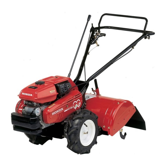
Page 14: Component Identification
COMPONENT IDENTIFICATION MAIN CLUTCH LEVER ENGINE SWITCH DIFFERENTIAL LOCK LEVER THROTTLE LEVER GEARSHIFT LEVER AIR CLEANER FUEL TANK CAP FUEL METER ENGINE SERIAL NUMBER HANDLE HEIGHT ADJUSTER ENGINE OIL FILLER CAP/ DIPSTICK CHOKE LEVER STARTER GRIP FRAME SERIAL NUMBER FUEL VALVE... - Page 15 ENGINE UPPER COVER SPARK PLUG MUFFLER DRAG BAR V-BELT COVER MUD GUARD ROTARY TINES...
-
Page 16: Pre-Operation Check
PRE-OPERATION CHECK Engine oil Engine oil is a major factor affecting engine performance and service life. Non-detergent or vegetable oils are not recommended. Be sure to check the tiller on a level surface with the engine stopped. Recommended oil Use 4-stroke motor oil that meets or exceeds the requirements for API service category SE or later (or equivalent). -
Page 17: Transmission Oil
Transmission oil Place the tiller on a level surface and remove the oil filler cap. The oil should be level with the lower edge of the oil filler hole. Add high quality engine oil if the level is low. TRANSMISSION OIL FILLER CAP UPPER LIMIT LOWER EDGE OF THE OIL FILLER HOLE... -
Page 18: Fuel
Fuel Remove the fuel tank cap, and check if the fuel is up to the level mark. If the fuel level is low, refill with recommended gasoline up to the level mark. Use unleaded gasoline with a Research Octane Number of 91 or higher (a Pump Octane Number of 86 or higher). -
Page 19: Gasoline Containing Alcohol
Gasolines containing alcohol If you decide to use a gasoline containing alcohol (gasohol), be sure it’s octane rating is at least as high as that recommended by Honda. There are two types of ‘‘gasohol’’: one containing ethanol, and the other containing methanol. -
Page 20: Tire Pressure
Tools and Attachments To install a tool or attachment on the tiller, follow the instructions furnished with the tool or attachment. Ask your Honda dealer for advice if you encouter any problem or difficulty in installing a tool or attachment. -
Page 21: Tightening The Rotary Installation Part
Carry out the check with the tiller on a level spot and the engine stopped. Wear thick gloves when checking or tightening the rotary part. Use only a genuine Honda replacement rotary tine. Check for looseness in fastened parts. Securely tighten all loose parts. Check for worn, bent or other damaged rotary tines. -
Page 22: Starting The Engine
STARTING THE ENGINE Exhaust contains poisonous carbon monoxide gas; exposure can cause loss of consciousness and may lead to death. Never run the engine in an enclosed or confined area. The muffler becomes very hot during operation and remains hot for a while after stopping the engine. - Page 23 Make sure the gearshift lever is in the NEUTRAL position. GEARSHIFT LEVER NEUTRAL POSITION Turn the engine switch ON. ・ ・ ・ ENGINE SWITCH...
- Page 24 In cold weather and when the engine is cold, move the choke lever to the CLOSE position. Do not use the choke if the engine is warm or the air temperature is high. ・ ・ ・ ・ ・ CLOSE CHOKE LEVER CLOSE Move the throttle lever about 30 degrees from the extreme right...
- Page 25 Pull the starter grip lightly until STARTER GRIP you feel resistance, then pull briskly in the direction of the arrow as shown. Hold the handle with your left hand and start the engine by pulling out the starter grip. Do not allow the starter grip to snap back against the engine.
- Page 26 High altitude performance can be improved by specific modifications to the carburetor. If you always operate the tiller at altitude higher than 1,500 m (5,000 feet) above sea level, have your authorized Honda dealer perform these carburetor modifications. Even with suitable carburetor jetting, engine horsepower will decrease approximately 3.5 % for each 300 m (1,000 foot) increase in altitude.
-
Page 27: Tiller Operation
TILLER OPERATION Handlebar height adjustment Before adjusting the handlebar, place the tiller on the firm level ground to prevent the handle from collapsing accidentally. Remove the handlebar height adjusting bolt and set the handlebar in a position that is convenient for use. The height of the handlebar can be adjusted to 4 positions to suit the work contents and the operator’s height. -
Page 28: Tilling Depth Adjustment
Tilling depth adjustment To adjust the tilling depth, remove the locking bolt and move the drag bar up or down. Carry out the adjustment with the tiller on a level spot and the engine stopped. Adjustment method Use the gage lines and indentations on the drag bar to adjust the tilling depth. -
Page 29: Gear Selection
Gear selection Return the throttle lever to the idle position and disengage the main clutch before moving the shift lever. Avoid using excessive force on the shift lever. Gearshift lever Select a gear position in accordance with the contents of the Gear Selection Table. -
Page 30: Main Clutch Operation
Main clutch operation Main clutch lever The tiller can be run or stopped by operating the main clutch lever. When operating the tiller, always walk behind and in the center of the tiller and hold the handlebar with both hands. If the tiller becomes imbalanced, an unforeseen accident may occur. -
Page 31: Normal Operating Angle
Normal operating angle Lower the handle slightly so the front of the machine is raised about ∼ 8°. 6 8° ∼ To get the maximum advantage from the tiller, try to hold the machine at the angle shown while you are tilling the ground: Do not use the tiller with a rotor whose diameter is in excess of 326 mm. -
Page 32: Differential Lock Operation
Differential lock operation For normal operation set the differential lock lever in the UNLOCK position. This improves the tiller’s turning ability. When the ground is soft and one wheel tends to slip or when only one side is to be tilled, set the differential lock lever in the LOCK position. -
Page 33: Tilling Work
Turning (when moving) Turning the tiller during high-speed operation causes the tiller to turn abruptly and become unstable, resulting in injury or accident. Do not turn the tiller when it is moving uphill or downhill. When the tiller is turned on a slope, it may abruptly move in an unforeseen direction, resulting in an accident, injury, or damage to the tiller. -
Page 34: Stopping The Engine
STOPPING THE ENGINE Release the main clutch lever. MAIN CLUTCH LEVER ・ ・ ・ DISENGAGED Move the throttle lever toward the ‘‘L’’ position and reduce the engine speed. THROTTLE LEVER ‘‘L’’ Set the gearshift lever in the NEUTRAL position. GEARSHIFT LEVER NEUTRAL POSITION... - Page 35 Turn the engine switch OFF. ・ ・ ・ ・ ・ ENGINE SWITCH Turn the fuel valve to the OFF position. FUEL VALVE ・ ・ ・ ・ ・ To stop the engine in an emergency, release the main clutch lever and turn the engine switch OFF.
-
Page 36: Maintenance
If the engine must be run, make sure the area is well ventilated. Use only genuine Honda parts or their equivalent for maintenance or repair. Replacement parts which are not of equivalent quality may damage the tiller. -
Page 37: Engine Oil Change
Engine oil change Change the oil when the engine is warm to assure rapid and complete draining. Remove the oil drain bolt and the filler cap to drain. Tilt the engine slightly forward and allow all of the oil to drain. Reinstall and tighten the oil drain bolt and fill engine with oil to the upper limit oil level (See page for recommended oil). -
Page 38: Air Cleaner Service
Air cleaner service A dirty air cleaner will restrict air flow to the carburetor. To prevent carburetor malfunction, service the air cleaner regularly. Service more frequently when operating the engine in extremely dusty areas. Never use gasoline or low flash point solvents for cleaning the air cleaner element. -
Page 39: Fuel Strainer Cup Cleaning
To clean the paper element, either blow compressed air through it from the inside or tap it gently. If the element is extremely dirty, replace it. Securely install the filter and the air cleaner cover. Close the engine upper cover and turn the cover stopper to the LOCK position. -
Page 40: Spark Plug Service
Spark plug service Recommended spark plug: BPR5ES (NGK) W16EPR-U (DENSO) To ensure proper engine operation, the spark plug must be properly gapped and free of deposits. SPARK PLUG WRENCH Open the engine upper cover (refer to page 35) and take off the spark plug cap. -
Page 41: Throttle Cable Adjustment
Throttle cable adjustment Loosen the lock nut and turn the adjusting nut until the free play in the throttle lever at the end of the lever is between: 5.0 10.0 mm (2.0 3.9 in) − − THROTTLE After adjusting the free play, tighten LEVER the lock nut firmly. -
Page 42: Differential Lock Cable Adjustment
Differential lock cable adjustment If the differential lock cable is not fully adjusted, it may become impossible to replace the differential. Ajust the differential lock lever so that the end has the free play dimensions shown in the figure. Free play: 1.0 4.0 mm (0.04 0.16 in) −... -
Page 43: Checking And Replacing Rotary Tines
Checking and replacing rotary tines Wear thick gloves to protect your hands. Carry out the check or replacement work with the tiller on a level spot and the engine stopped. Wear thick gloves to prevent injury to hands. Place a wooden block under the rotary tine shaft to prevent tines from dropping. - Page 44 If necessary, replace with a new installation pin and lock pin. Use Honda authorized parts when replacing rotary tines. To prevent the installation pin from falling out, insert the lock pin in the direction opposite to the direction of rotation of the rotary part.
- Page 45 Installing rotary tines Arrange the rotary tines as shown in the figure. If the arrangement or orientation is changed, vibration may be produced, and normal tilling operation may become impossible. Facing the Forward direction, install right-side tines 1, 2, 7, and 8 and left-side tines A, B, G, and H so that they are facing inside, and install right-side tines 3, 4, 5, and 6 and left-side tines C, D, E, and F so that they are facing outside.
- Page 46 While pushing the rotary tines in the direction of rotation and the opposite direction, fasten the nut securely. PUSH TINE BOLT DIRECTION OF ROTATION These points should make contact. When assembling the rotary tines and holders, the match marks have to be aligned. If they are wrongly assembled, vibration will be produced.
-
Page 47: Transporting/Storage
TRANSPORTING/STORAGE When transporting the tiller, turn the fuel valve OFF and keep the tiller level to prevent fuel spillage. Fuel vapor or spilled fuel may ignite. Before storing the unit for an extended period: Be sure the storage area is free of excessive humidity and dust. Drain the fuel. -
Page 48: Troubleshooting
Is the spark plug in good condition? Remove and inspect the spark plug. Clean, readjust gap and dry the spark plug. Replace it if necessary. If the engine still does not start, take the tiller to an authorized Honda dealer. -
Page 49: Specifications
SPECIFICATIONS Model FR750 Type Dimensions, Length 1,500 mm (59.1 in) Width 570 mm (22.4 in) Height 1,140 mm (44.9 in) Dry mass [weight] 91 kg (201 lbs) Tire size 3.50-7 Maximum handle height 1,230 mm (48.4 in) Engine Model GX200... - Page 50 Rotary Tilling depth control Adjustable drag bar Tine shaft speed 238 rpm Specifications are subject to change without notice due to improvements.
- Page 51 MEMO...
- Page 52 MEMO...
- Page 53 MEMO...
-
Page 54: Major Honda Distributor Addresses
W e i t e r e I n f o r m a t i o n e n e r h a l t e n S i e g e r n e v o m H o n d a - Kundeninformationszentrum unter der folgenden Adresse oder Telefonnummer: DIRECCIONES DE LOS PRINCIPALES CONCESIONARIOS Honda Para obtener más información, póngase en contacto con el Centro de información para clientes Honda en la dirección o número de teléfono siguientes:... - Page 55 AUSTRIA CROATIA FINLAND Honda Motor Europe (North) Hongoldonia d.o.o. OY Brandt AB. Hondastraße 1 Jelkovecka Cesta 5 Tuupakantie 7B 2351 Wiener Neudorf 10360 Sesvete − Zagreb 01740 Vantaa Tel. : + 43 (0)2236 690 0 Tel. : + 385 1 2002053 Tel.
- Page 56 @ honda.produtos honda-eu. @ ICELAND NETHERLANDS REPUBLIC OF BELARUS Bernhard ehf. Honda Motor Europe (North) Vatnagardar 24-26 Afd. Power Equipment- Scanlink Ltd. 104 Reykdjavik Capronilaan 1 Kozlova Drive, 9 Tel. : + 354 520 1100 1119 NN Schiphol-Rijk 220037 Minsk Tel.
- Page 57 @ ventas aucasa.com @ taller aucasa.com @ SLOVAKIA REPUBLIC SWEDEN UNITED KINGDOM Honda Slovakia, spol. s r.o. Honda Nordic AB Honda (UK) Power Equipment Prievozská 6 821 09 Bratislava Box 50583 - Västkustvägen 17 470 London Road Tel. : +...
-
Page 58: "Ec Declaration Of Conformity" Content Outline
"EC Declaration of Conformity" CONTENT OUTLINE "CE-Déclaration de conformité" DESCRIPTION DE TABLE DES MATIERES "EU-Konformitätserklärung" INHALTSÜBERSICHT DESCRIPCIÓN GENERAL DEL CONTENIDO DE LA "Declaración de Conformidad CE" DESCRIZIONE DEL CONTENUTO DELLA "Dichiarazione CE di Conformità" *1: see specification page. á *1: consulte la p gina de las é... - Page 62 oHonda Motor Co., Ltd. 2009 efgsY1200.2009.09 36777620 Printed in Japan 00X36-777-6200...
Need help?
Do you have a question about the FR750 and is the answer not in the manual?
Questions and answers