Table of Contents
Advertisement
Advertisement
Table of Contents

Related Manuals for Fagor PPC-21W Series


Summary of Contents for Fagor PPC-21W Series
- Page 1 CNCelite 8060/8065 8070 Panel PC. Ref. 2106...
- Page 2 CNC and at the drives. • Tendency test on analog axes. FAGOR AUTOMATION shall not be held responsible for any personal injuries or physical damage caused or suffered by the CNC resulting from any of the safety elements being disabled.
-
Page 3: Table Of Contents
P a n e l P C . I N D E X About this manual......................... 5 About the product......................... 7 Declaration of CE conformity and warranty conditions............... 13 Safety conditions........................15 Returning conditions........................19 CNC maintenance. - Page 4 P a n e l P C . CNCelite 8060 8065 8070 . 2106 ꞏ4ꞏ...
-
Page 5: About This Manual
Responsibility exemption. The information described in this manual may be subject to changes due to technical modifications. Fagor Automation reserves the right to change the contents of this manual without prior notice. Trademarks. This manual may contain third-party trademarks or trade names, however, they do not have them associated ®... - Page 6 P a n e l P C . CNCelite 8060 8065 8070 . 2106 ꞏ6ꞏ...
-
Page 7: About The Product
Some of the features described in this manual are dependent on the acquired software options. The active software options for the CNC can be consulted in the diagnostics mode (accessible from the task window by pressing [CTRL] [A]), under software options. Consult Fagor Automation regarding the software options available for your model. - Page 8 There is no need to work with part programs, have any previous programming knowledge or be familiar with Fagor CNCs. Working in conversational mode is easier than in ISO mode, as it ensures proper data entry and minimizes the number of operations to be defined.
- Page 9 P a n e l P C . Software option Description. SOFT SYNCHRONISM Option to enable the synchronization of paired axes and spindles, in speed or position, and through a given ratio. SOFT KINEMATIC CALIBRATION Option to enable tool calibration. For the first time, this kinematics calibration allows for the kinematics offsets to be calculated using various approximate data and, also, from time to time to correct any possible deviations...
- Page 10 2 other sections, pockets, ruled surfaces, etc. SOFT PPTRANS Option to enable the program translator, which can convert programs written in other languages to Fagor ISO code. SOFT DMC Option to enable the DMC (Dynamic Machining Control).
- Page 11 P a n e l P C . Software option Description. SOFT MANUAL NESTING Option to enable nesting in the automatic option. Nesting consists of creating a pattern on the sheet material using previously defined figures (in dxf, dwg or parametric files), so as to use most of the sheet as possible.
- Page 12 P a n e l P C . CNCelite 8060 8065 8070 . 2106 ꞏ12ꞏ...
-
Page 13: Declaration Of Ce Conformity And Warranty Conditions
P a n e l P C . DECLARATION OF CE CONFORMITY AND WARRANTY CONDITIONS. DECLARATION OF CONFORMITY The declaration of conformity is available from the downloads section of the Fagor Automation corporate website. https://www.fagorautomation.com/en/downloads/ Type of file: Declaration of conformity. - Page 14 P a n e l P C . CNCelite 8060 8065 8070 . 2106 ꞏ14ꞏ...
-
Page 15: Safety Conditions
Read the following safety measures in order to prevent harming people or damage to this product and those products connected to it. Fagor Automation shall not be held responsible of any physical or material damage originated from not complying with these basic safety rules. - Page 16 Central unit enclosure. To maintain the right ambient conditions in the enclosure of the central unit, it must meet the requirements indicated by Fagor. See the corresponding chapter in the hardware manual. Power switch. This switch must be easy to access and at a distance between 0.7 and 1.7 m (2.3 and 5.6 ft) off the floor.
- Page 17 P a n e l P C . Symbols that the product may carry. Ground symbol. This symbol indicates that that point must be under voltage. ESD components. This symbol identifies the cards as ESD components (sensitive to electrostatic discharges). CNCelite 8060 8065 8070...
- Page 18 P a n e l P C . CNCelite 8060 8065 8070 . 2106 ꞏ18ꞏ...
-
Page 19: Returning Conditions
P a n e l P C . RETURNING CONDITIONS. Pack it in its original package along with its original packaging material. If you do not have the original packaging material, pack it as follows: Get a cardboard box whose 3 inside dimensions are at least 15 cm (6 inches) larger than those of the unit itself. - Page 20 P a n e l P C . CNCelite 8060 8065 8070 . 2106 ꞏ20ꞏ...
-
Page 21: Cnc Maintenance
• Do not handle the connectors with the unit supplied with power. Before handling these connectors (I/O, feedback, etc.), make sure that the unit is not powered. • Do not get into the inside of the unit. Only personnel authorized by Fagor Automation may access the interior of this unit. - Page 22 P a n e l P C . CNCelite 8060 8065 8070 . 2106 ꞏ22ꞏ...
-
Page 23: New Features
P a n e l P C . NEW FEATURES. Ref. 2106 Manual reference: June, 2021 Date of publication: v2.00 Associated software: Below is a list of the features added in this software version and the manuals that describe them. List of features. - Page 24 P a n e l P C . CNCelite 8060 8065 8070 . 2106 ꞏ24ꞏ...
-
Page 25: Chapter 1 Previous Information
In order to avoid personal injuries and damage to this product or to those connected to it, read carefully the section on safety conditions in the introduction to this manual. Fagor Automation shall not be held responsible of any physical damage or defective unit resulting from not complying with these basic safety regulations. - Page 26 P a n e l P C . CNCelite 8060 8065 8070 . 2106 ꞏ26ꞏ...
-
Page 27: Chapter 2 Ppc-21W
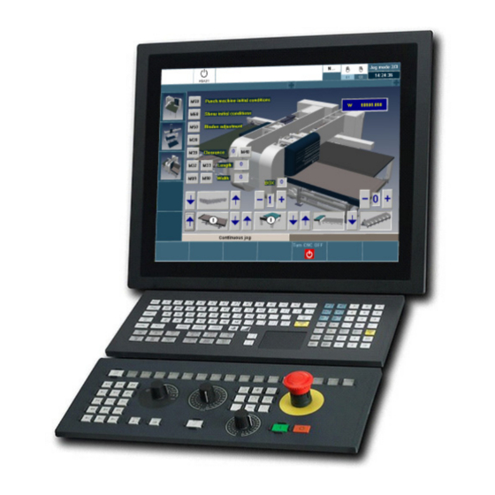
P a n e l P C . PPC-21W. Panel PC with 21.5 multi-touch monitor to control, operate and monitor the CNC via an ethernet connection. The PPC-21W allows the user to operate the CNC using the touch screen or a USB keyboard (for example, the HORIZONTAL KEYB 2.0 + TOUCHPAD). In both cases, the user can work with the PPC in just the same way as if being in front of the CNC screen. -
Page 28: Specifications
• 1 audio input. • 1 audio output. CNCelite Both the touch controller and VGA connection for the monitor must be connected to the Fagor panel 8060 8065 PC. Always use the cables supplied by Fagor for the unit. 8070 . -
Page 29: General Diagram (Ppc-21W)
P a n e l P C . General diagram (PPC-21W). 2.2.1 Networking, without access to the company network. PPC-21W ETHERNET ETHERNET USB 2.0 CNC U65 HORIZONTAL KEYB 2.0 + HBH3 TOUCHPAD HANDHELD TERMINAL CNC U70 OP PANEL Connection. Description. USB 2.0 Connection of a USB keyboard to the PPC-21W. -
Page 30: Connecting To An Ethernet Network Through A Switch
P a n e l P C . 2.2.2 Connecting to an Ethernet network through a switch. COMPANY NETWORK ETHERNET SWITCH SFNB 5TX ETHERNET ETHERNET ETHERNET CNC U65 PPC-21W HBH3 HANDHELD TERMINAL CNC U70 USB 2.0 OP PANEL HORIZONTAL KEYB 2.0 + TOUCHPAD Connection. -
Page 31: Dimensions
P a n e l P C . Dimensions. inch inch 558.40 21.98 548.00 21.57 349.80 13.77 339.25 13.36 114.41 4.50 121.41 4.78 CNCelite 8060 8065 8070 . 2106 ꞏ31ꞏ... -
Page 32: Enclosure And Mounting Of The Module
• To improve heat dissipation, install an internal fan inside the enclosure for air circulation. Before building an enclosure with glass fiber u another poor heat dissipating material, contact Fagor Automation. Dimensions of the cut off part and the enclosure. - Page 33 P a n e l P C . Recommended minimum clearances between the PPC-21W and the enclosure walls. inch D (*) > 50 > 1.97 (*) Minimum recommended distance. Dissipated power inside the enclosure. To calculate the total surface area the enclosure must have to dissipate the heat inside, we must consider the dissipated power for all the elements that generate heat inside the enclosure.
-
Page 34: Securing The Module
P a n e l P C . 2.4.3 Securing the module. The module must be installed in a proper enclosure that may be located on the machine or on an external support. To insert the unit into the enclosure, it must have a big enough hole to allow to insert it easily, without obstacles and without forcing the unit. - Page 35 P a n e l P C . Rest the monitor inside the enclosure on the lower stop screws and push the top part until the pressure hooks support the monitor. Fasten the PPC-21W at the rear, using all the attachment fixtures (D). 0.7 Nm CNCelite 8060 8065...
-
Page 36: Voltage Supply For The Module
(B)Monitor power: 12 V DC (consult Fagor Automation). (C)Panel PC power: 24 V DC. The monitor has two different voltage power supply ports (24 and 12 V DC). Fagor Automation recommends using 24 V DC (Phoenix-type connector) to power the monitor. -
Page 37: Hardware Functionalities
P a n e l P C . Hardware functionalities. 2.6.1 Rear keyboard. The rear keyboard allows the monitor video signal ("2.7 Configuring the video signal from the monitor.") to be configured and to navigate through the OSD menu ("2.9 OSD (On Screen Display) menu."). -
Page 38: Monitor (Lower End Connectors)
DC jack connector for the external current adapter. See "2.5 Voltage supply for the module." on page 36. Fagor Automation recommends 24 V DC power for the monitor. Consult Fagor Automation before using CNCelite the 12 V DC option. 8060 8065 Both monitor power suppliers (24 and 12 V DC) must never be connected at the same time. -
Page 39: Panel Pc (Lower End Connectors)
2 USB 2.0 Type-A ports, Plug & Play compatible. The USB interface is compliant with USB EHCI specification, rev. 2.0. Connect the monitor’s T/S USB (touch controller) output to one of these inputs. Always use the cable supplied by Fagor for the unit. ꞏUSB 3.0ꞏ 2 USB 3.0 Type-A ports. - Page 40 P a n e l P C . ꞏLAN A / LAN Bꞏ Ethernet. The PPC-21W has 4 RJ45 LAN ports, two at the lower end (LAN A / LAN B) and two at the upper end (LAN C / LAN D). All ports comply with the IEEE 802.3u 10 / 100Base-T CSMA/CD standard and are compliant with the IEEE 802.3ab 1000Base-T specification.
- Page 41 P a n e l P C . Power button. Button to turn the panel PC on and off. ꞏRSTꞏ Reset button. Button to activate the hardware reset function. ꞏTx Rxꞏ Transmission and reception LEDs. Data transmission and reception LEDs on the COM ports. ꞏBTRꞏ...
-
Page 42: Panel Pc (Top End Connectors)
P a n e l P C . 2.6.4 Panel PC (top end connectors). Bottom view. (A)COM1 / COM2RS-232 serial line. (B)LAN C / LAN DEthernet. (C)HD AudioHigh definition audio output. (D)HD Expansion.n/a. ꞏCOM1 / COM2ꞏ RS-232 serial line. 2 COM ports for RS-232 serial lines, 50 ~ 115.2 kbps. Plug-in part 9-pin female SUB-D HD connector. -
Page 43: Configuring The Video Signal From The Monitor
P a n e l P C . Configuring the video signal from the monitor. The buttons to configure the monitor video signal are on the back. This keyboard is also used for the OSD menu. Button. Description. Turns the monitor on and off. Power Automatically adjusts the clock, phase, horizontal position and vertical position. -
Page 44: Connection
(A)VGA video output on the panel PC. (B)VGA Video input on the monitor. Cable characteristics. Fagor Automation supplies the necessary cable for the VGA connection between the panel PC and the monitor. Always use the cable supplied by Fagor for the unit. CNCelite 8060 8065 8070 . -
Page 45: Touch Controller
û (A)The monitor’s touch controller output. (B)Generic USB 2.0 input on the panel PC. Cable characteristics. Fagor Automation supplies the necessary cable for the touch controller. Always use the cable supplied by Fagor for the unit. CNCelite 8060 8065 8070 . -
Page 46: Ethernet (Fast Ethernet / Gigabit Ethernet)
P a n e l P C . 2.8.3 Ethernet (Fast Ethernet / Gigabit Ethernet). The PPC-21W has 4 RJ45 LAN ports, two at the lower end (LAN A / LAN B) and two at the upper end (LAN C / LAN D). All ports comply with the IEEE 802.3u 10 / 100Base-T CSMA/CD standard and are compliant with the IEEE 802.3ab 1000Base-T specification. - Page 47 P a n e l P C . Element connection. In order to ensure proper performance, the connection cable must be inserted all the way into the connectors so they're latched. This ensures that the cable is properly latched and does not come off due to vibration.
-
Page 48: Osd (On Screen Display) Menu
P a n e l P C . OSD (On Screen Display) menu. The selected values are stored in the memory of the monitor after pressing the [Menu/Sel] button at the end of the wait time. The saved values are not lost when the monitor is turned off. -
Page 49: Osd Menu
P a n e l P C . 2.9.2 OSD menu. To display the OSD menu, press the MENU key on the back of the monitor. Icon. Description. Video input. Contrast/Brightness. Geometry (for DVI input). Temperature color. Language. OSD configuration. Auto-configuration. - Page 50 P a n e l P C . Video input. Select this menu icon using the [Left] and [Right] keys and press the [Menu/Sel] key to confirm the selection. OSD sub-menu. Contrast/Brightness. Select this menu icon using the [Left] and [Right] keys and press the [Menu/Sel] key to confirm the selection.
- Page 51 P a n e l P C . Geometry (for DVI input). Select this menu icon using the [Left] and [Right] keys and press the [Menu/Sel] key to confirm the selection. OSD sub-menu. Temperature color. Select this menu icon using the [Left] and [Right] keys and press the [Menu/Sel] key to confirm the selection.
- Page 52 P a n e l P C . OSD configuration. Select this menu icon using the [Left] and [Right] keys and press the [Menu/Sel] key to confirm the selection. OSD sub-menu. Auto-configuration. Select this menu icon using the [Left] and [Right] keys and press the [Menu/Sel] key to confirm the selection.
- Page 53 P a n e l P C . Restore. Select this menu icon using the [Left] and [Right] keys and press the [Menu/Sel] key to confirm the selection. OSD sub-menu. Exit. Select this menu icon using the [Left] and [Right] keys and press the [Menu/Sel] key to confirm the selection.
-
Page 54: Locks And Unlocks The Osd Menu
P a n e l P C . 2.9.3 Locks and unlocks the OSD menu. Locks the OSD menu. Press the [Left]+[Right] keys and the following message will appear on screen. Do not release the keys until the screen indicates that the operation has been completed. -
Page 55: Chapter 3 Ppc-19
P a n e l P C . PPC-19. Panel PC with 19 multi-touch monitor to control, operate and monitor the CNC via an ethernet connection. The PPC-19 allows the user to operate the CNC using the touch screen or a USB keyboard (for example, the HORIZONTAL KEYB 2.0 + TRACKHPAD). -
Page 56: Specifications
P a n e l P C . Specifications. Type. Description. General. • 19" monitor (1280 × 1024 px), capacitive multi-touch (10 points). • Dimensions (width x height x depth) - 480 × 400 × 60.40 mm. - 18.90" × 15.75" × 2.37". •... -
Page 57: General Diagram (Ppc-19 )
P a n e l P C . General diagram (PPC-19 ). 3.2.1 Point-to-point connection with the CNC. PPC-19 ETHERNET ETHERNET USB 2.0 CNC U65 HORIZONTAL KEYB 2.0 + HBH3 TOUCHPAD HANDHELD TERMINAL CNC U70 OP PANEL Connection. Description. USB 2.0 Connection of a USB keyboard to the PPC-19. -
Page 58: Connecting To An Ethernet Network Through A Switch
P a n e l P C . 3.2.2 Connecting to an Ethernet network through a switch. COMPANY NETWORK ETHERNET SWITCH SFNB 5TX ETHERNET ETHERNET ETHERNET CNC U65 PPC-19 HBH3 HANDHELD TERMINAL CNC U70 USB 2.0 OP PANEL HORIZONTAL KEYB 2.0 + TOUCHPAD Connection. -
Page 59: Dimensions
P a n e l P C . Dimensions. inch inch 18.90 18.15 15.75 52.60 2.07 60.40 2.37 CNCelite 8060 8065 8070 . 2106 ꞏ59ꞏ... -
Page 60: Enclosure And Mounting Of The Module
• To improve heat dissipation, install an internal fan inside the enclosure for air circulation. Before building an enclosure with glass fiber u another poor heat dissipating material, contact Fagor Automation. Dimensions of the cut off part and the enclosure. - Page 61 P a n e l P C . Minimum distances recommended to the enclosure walls. inch D (*) 1.97 (*) Minimum recommended distance. Dissipated power inside the enclosure. To calculate the total surface area the enclosure must have to dissipate the heat inside, we must consider the dissipated power for all the elements that generate heat inside the enclosure.
-
Page 62: Securing The Module
P a n e l P C . 3.4.3 Securing the module. The module must be installed in a proper enclosure that may be located on the machine or on an external support. To insert the unit into the enclosure, it must have a big enough hole to allow to insert it easily, without obstacles and without forcing the unit. -
Page 63: Voltage Supply For The Module
P a n e l P C . Voltage supply for the module. Power supply. Monitor power: 12 ~ 24 V DC. Power the monitor with a 12 ~ 24 V DC power supply. Signal. Function. - - -. 0 V reference signal. Power supply. -
Page 64: Hardware Functionality. Connectors
P a n e l P C . Hardware functionality. Connectors. Connector. Description. USB 2.0 2 USB 2.0 Type-A ports. RS-232/422/485 2 RS-232/422/485 serial lines. DVI-D Video signal output. USB 2.0 1 USB 2.0 Type-A ports. USB 3.0 1 USB 3.0 Type-A ports. 2 RJ45 LAN ports (10/100/1000 Mbps). - Page 65 Power status LED (green LED). The LED turns on when the panel PC is powered, otherwise the LED is turned off. ꞏ24 V DC INꞏ Supply input (recommended). Option recommended by Fagor Automation to power the monitor. Plug-in part 3-pole Phoenix-type connector (5.08 mm pitch). Rated current; 16 A.
-
Page 66: Connection
P a n e l P C . Connection. 3.7.1 Ethernet (Fast Ethernet / Gigabit Ethernet). RJ-45 The PPC-19 can be configured as an additional node on a local network or it may be connected point-to-point to the CNC. Connector. All ports have two LEDs to indicate whether the PPC-19 is connected to the network (green LED) and if data are being transmitted (yellow LED). -
Page 67: Chapter 4 Fagorconnect Application
Press the "Install" button to start the installation and follow the instructions that appear on screen. • To install the application on a Fagor Panel PC, it must be in administrator mode (with the disk unprotected). See "4.4 Work modes."... -
Page 68: The Fagorconnect Application
P a n e l P C . The FagorConnect application. The main objective of the application is to connect the Panel PC to the CNC through the remote Desktop as soon as the application starts and in a way that is transparent to the user. After establishing the connection, the Panel PC will display the same information as the CNC, so that the user can work with the Panel PC just as if it were a screen connected to the CNC. -
Page 69: Configure The Application
P a n e l P C . Configure the application. The "Configuration" button at the top shows the window to configure the connection to the CNC. When the application starts, it displays the current configuration saved in the FagorConnect.ini file. The configuration is saved in this file when the "Save Configuration" or "Connect”... -
Page 70: Work Modes
• $Recycler.bin Recycling bin. • C:\Public Network shared folder. • C:\Program Files (x86)\Fagor Automation\FagorConnect\FagorConnect.ini Configuration file for the FagorConnect application. • C:\Program Files (x86)\Fagor Automation\FagorConnect\FagorConnect.rdp Configuration file for the remote desktop connection. In administrator mode, the buttons "Add new file/folder" and "Remove file/folder" allow you to add and remove files/folders in the protected files/folders list. -
Page 71: Ref . 2106
P a n e l P C . Diagnosis. The "Diagnosis" button at the top shows information about the Panel PC itself. The "Save to file" button allows you to save the information in a file. Accessing Panel PC resources from the CNC. The Panel PC is configured to export its resources so that the CNC can see your hard drive and any possible pen drives that are connected. - Page 72 P a n e l P C . User notes: CNCelite 8060 8065 8070 . 2106 ꞏ72ꞏ...
- Page 73 P a n e l P C . User notes: CNCelite 8060 8065 8070 . 2106 ꞏ73ꞏ...
- Page 74 FAGOR AUTOMATION Fagor Automation S. Coop. Bº San Andrés, 19 - Apdo. 144 E-20500 Arrasate-Mondragón, Spain Tel: +34 943 039 800 Fax: +34 943 791 712 E-mail: info@fagorautomation.es www.fagorautomation.com...
Need help?
Do you have a question about the PPC-21W Series and is the answer not in the manual?
Questions and answers