
Subscribe to Our Youtube Channel
Related Manuals for Fagor Innova 30i-E


Summary of Contents for Fagor Innova 30i-E
- Page 1 Fagor Automation S. Coop. 30i-E / 30i-E B Installation/operation manual Manual code: 14460149 Manual version: 1111 Software version: 1.xx...
-
Page 2: Table Of Contents
INDEX DRO description ..................4 Front panel ........................4 Turning the unit on and off....................5 DRO operation .................... 6 Display modes ........................6 Incremental, absolute and with respect to Machine Reference Zero ......7 2.2.1 Example ..........................8 2.2.1.1 Absolute mode ........................8 2.2.1.2 Incremental mode ....................... - Page 3 DRO installation ..................26 Installation of the built-in model ................... 26 Rear panel ........................27 General technical characteristics ................. 28 Connections........................29 3.4.1 Connection of the feedback systems ................29 3.4.2 Input/output connection. Connector X4 ................30 Easy setup ........................32 3.5.1 Accessing the "Easy Setup"...
-
Page 4: Dro Description
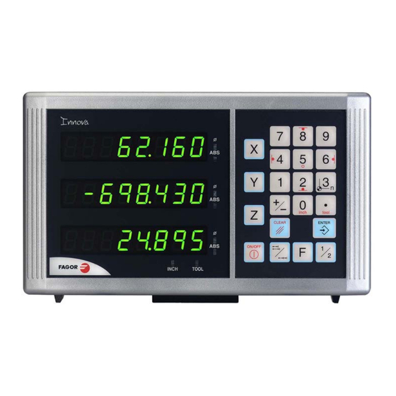
1 DRO description 1.1 Front panel Each axis display has eight 14.1mm high LEDs and another one for the minus sign (- Description of LED's and keys: It stays on when operating in absolute mode and off when in incremental mode. To access it or quit it, press this key. -
Page 5: Turning The Unit On And Off
1.2 Turning the unit on and off It turns on automatically when applying voltage or after pressing the on/off key. It shows Fagor dro or the corresponding error code. See the error table and PAR11 for more options. Turns the DRO on or off. -
Page 6: Dro Operation
2 DRO operation 2.1 Display modes MM / INCH conversion To display the position of the axes either in millimeters or inches by pressing this key depending on whether the INCH led is off or on respectively. Fine / coarse resolution To turn off the last decimal digit (coarse resolution) for cases in which fine resolution is excessive, simply by pressing this key. -
Page 7: Incremental, Absolute And With Respect To Machine Reference Zero
2.2 Incremental, absolute and with respect to Machine Reference Zero A coordinate DRO displays the present coordinate of one or several axes. Coordinate means the distance from on e point or position with respect with another chosen as reference. These DROs can display the position of the axes in incremental or absolute mode or referring to home. -
Page 8: Example
2.2.1 Example We will drill the holes of the following part as moving examples in incremental and absolute modes. First, set the dat um point on the part to be machined as described in the section "Datum point (part zero) to work with tool compensation" on page The axis must be positioned without tool compensation (canceled) because the hole coordinates are referred to the center and no tool radius compensation is needed. -
Page 9: Incremental Mode
2.2.1.2 Incremental mode “ABS” off Set the dro in incremental mode. ABS LED off First method: Presetting incremental zero after each drill. Starting at point A. (B) [14.000] Move the axis until the display reads [14.000] (B position) and drill the hole. Set the X axis to zero. -
Page 10: Machine Reference Selection And Search
Fagor linear encoders have reference marks every 50 mm all along its length. In order to use these marks properly, choose an area on the axis, for example in the middle of the measuring length or at one end. -
Page 11: Operating With Tools
2.4 Operating with tools It is possible to de fine a tool a nd later compensate for its dimensions wh ile machining. 2.4.1 Entering tool dimensions The Y axis blinks waiting for the tool value to be entered. 20i-M.- It requests the tool diameter. 30i-M.- It requests the diameter on the Y axis and the length on the Z axis. -
Page 12: Datum Point (Part Zero) To Work With Tool Compensation
2.4.3 Datum point (part zero) to work with tool compensation Set the dro in absolute mode. Move the tool and touch the side of th e part, activate the corresponding compensation and set the axis to zero. In the example of the figure, the sequence would be: For the X axis, move the tool and touch it on the left side and press this key. -
Page 13: Special Operations
2.5 Special operations 2.5.1 EDM mode The dro activates th e outputs when the axis reaches the programmed position. See next subsection ”Programming the levels on page 14”. The are two ways to ope rate in th is mode dep ending on the value of installation parameter PAR20 bit 4. -
Page 14: Programming The Levels
PAR20 bit 4 = 1 (the outputs are deactivated when reaching the home position) P1 (Home) P6 (End) 2.5.1.1 Programming the levels The levels are set by installation parameters PAR40 (for output O1) through PAR45 (for output O6); to access them directly: The dro displays must be on, reading mode and press the following keys: The X axis display shows the word "... -
Page 15: Part Centering
2.5.2 Part centering Note: This feature is available when none of the axes have installation parameter PAR04(2)=1 (radius/diameter commutable). Part centering can be done as follows: - Set the dro in absolute mode. - Touch one side of the part with the tool. - Set the reading to zero pressing for an axis [CLEAR] [X] for one axis or [CLEAR] [Y] for the other one. -
Page 16: Inside Pocket
2.6.1 Inside pocket - Go into incremental. ABS LED OFF. "Datum point (part zero) to work - Preset the part zero or datum point (see section with tool compensation" on page Go to point A. For that: - Press these keystroke sequences. [-30.56] [-10.00] - Compensate for the tool. -
Page 17: Outside Pocket
2.6.2 Outside pocket - Go into incremental. ABS LED OFF. "Datum point (part zero) to work - Preset the part zero or datum point (see section with tool compensation" on page Go to point A. For that: - Press these keystroke sequences. [-18.24] [-10.00] - Compensate for the tool. -
Page 18: Access To Special Modes
2.7 Access to special modes Pressing [F] accesses the "special functions" menu. Pressing this key repeatedly displays the various available options. Pressing [ENTER] assumes the selected option. A function may be directly accessed by pressing [F] and then the function number: Function 1 = bolt hole drilling, 2 = linear drilling, 3 = hold, 4 = calculator, number... -
Page 19: Bolt-Hole Drilling
2.7.1.2 Bolt-hole drilling It allows up to 99 holes to be drilled in a bolt-hole pattern without having to calculate the coordinates (X Y) of each hole, by simply keying in some basic data. To access the bolt-hole drilling mode directly Example: CENTER Coordinate of the center of the bolt-hole (X = 37.899, and = 30.467) -
Page 20: Execution Of Bolt-Hole Drilling
2.7.1.3 Execution of bolt-hole drilling After entering this data, the DRO displays the text “HOLE 01” in the display “X” and turns the “Y” off. - After pressing this key to--- - ... show the position of the first hole: X -23,105 Y -6,190 - Move the axes until the displays read X 0.000 and Y 0.000 X 0.000 Y 0.000... -
Page 21: Linear Drilling
2.7.1.4 Linear drilling This features guides the user in the linear drilling operation. To access the "linear drilling" mode directly Requested data: DiST: Straight distance (gap) between two consecutive holes. HOLES: Number of holes to be drilled (3 in the figure). ALPHA: Angle in the trigonometric direction. -
Page 22: Calculator
2.7.3 Calculator This feature may be used to carry out mathematical and trigonometric operations as well as preset the desired axis with the result of the calculation or use the coordinates of the axes to carry out math operations. To access the calculator mode To quit the calculator mode. -
Page 23: Recall And Reset Modes
2.7.3.2 Recall and Reset modes Toggles between the recall and Preset modes. RECALL mode The recall mode lets enter the current axis position into the calculator. Enters the current position of the selected axis into the calculator. PRESET mode The preset mode lets preset the desired axis with the result of an operation. Presets the selected axis with the result of the calculation. -
Page 24: Part Angle Measuring
2.7.4 Part angle measuring To control the part orientation angle to properly machine the part. It calculates the angle between a particular side of the part and the horizontal (X axis) by simply touching two points on it. Alpha To do this, follow this procedure: - Move the tool until it touches the part at any point. -
Page 25: Corner Rounding
2.7.5 Corner rounding This features guides the user in the corner rounding process in the selected plane. The DRO guides the machining running several passes until obtaining the desired part. The number of passes depends on the tool radius being used. The smaller the tool diameter, the more passes will be required for a better part finish. -
Page 26: Dro Installation
3 DRO installation 3.1 Installation of the built-in model Dimensions of the enclosure hole for inserting the DRO Built-in DRO insertion Nut DIN 985 Bolt ISO 7380 M4 Inox M4 x 10 Inox 30iE - v1111 - Installation/Operation - (26/48) -
Page 27: Rear Panel
3.2 Rear panel On the back of the unit the following items may be found: 1. Three-prong power connector for AC and ground connection. 2. M6 mm terminal for general machine ground connection. 3. Mounting bracket Some of the following connectors might not be available depending on specific models: X1.- SUB-D HD type 15-pin female connector for 1st axis feedback device. -
Page 28: General Technical Characteristics
UL seal In order to comply with UL stand ards, this unit must be connected in the fin al application using a listed detachable cord set (BLEZ) with a molded three-prong plug and a suitable fitting to be connected to the seal equipment, rated minimum 300 V AC. -
Page 29: Connections
3.4 Connections 3.4.1 Connection of the feedback systems The feedback systems (linear or rotary encoders) are connected via SUB-D HD type 15-pin female connectors: X1 through X3. The latter (for the 2nd axis) is not available at the 10i model. Characteristics of feedback inputs: X1, X2 and X3: - Power consumption: 250 mA at the +5V input. -
Page 30: Input/Output Connection. Connector X4
3.4.2 Input/output connection. Connector X4 X4 is a 15-pin female SUB-D connector to connect 4 opto-coupled digital inputs and 6 opto-coupled digital outputs with solid state relays with normally ope n contacts that may be used to activate relays, beacons, etc. Characteristics of the inputs Rated voltage: +24 V DC Maximum voltage: +30 V DC... - Page 31 Outputs: The outputs that will be connected to an inductive load must have a 1N4000 diode or similar in anti-parallel. Open-collector outputs: LOAD LOAD Common Open-emitter outputs: LOAD LOAD Common 30iE - v1111 - Installation/Operation - (31/48)
-
Page 32: Easy Setup
Relay connection example: 3.5 Easy setup The "Easy Setup" may be used to set up the feedback of the DRO and to verify that the installation is correct and no feedback pulses are missed. It sets up the encoder resolution and the kind of reference marks being used as well as the positive counting (reading) direction. -
Page 33: Power And Machine Connection
The axis status will then switch to one of the following: Ready Feedback configured properly. It has set PAR00 (feedback reading direction), PAR01 (resolution), PAR03 (multiplying factor) and PAR14 (type of reference mark, I0) Repeat Wrong feedback setup, the process should be repeated. Error Error in the feedback system. - Page 34 To get into parameter editing The dro displays must be on, reading mode and press the following keys: The X axis display shows the word " COdE ". 060496 CODE: 060496 The displays of the DRO show PAR00. Once in re gular display mode, this parameter can also be edited by pressing th is keystroke sequence, so the work mode may be changed without having to go through all the previous steps.
-
Page 35: Parameters To Configure Axis Position Reading And Display
3.7 Parameters to configure axis position reading and display. The digits of digital parameters refer to the digits on the axis displays so digit "1" (that can be cha nged with the [1 ] key) corre sponds to t he rightmost digit and "8" to the leftmost digit. - Page 36 TTL multiplying factor (subdivision). Independent for each axis. Options: x4, x2, x1 and x0.5. The factory setting is x4 and it is the one used for FAGOR linear encoders. When using rotary encoders on linear axes, it should be calculating according to the...
- Page 37 PAR04 Axis display. Independent for each axis. Digit 8, 7, 6, 5, 4 Not being used at this time (they must be set to "0"), Turn the axis display off. 0 = No, 1 = Yes. Axis display toggle radius/diameter 0 = no toggle, 1 = toggle Axis display.
- Page 38 Not being used. Must be set to "0". Operate always in mm. Operate always in inches. Do not display "Fagor DRO" on power-up. If =0, normal zero setting and coordinate presetting (factory set) If =1, quick zeroing of the position value displayed on each axis.
- Page 39 The key affects one axis ( = 0) or both ( = 1). If it affects each axis independently, after pressing this key, one must press the axis key. It may toggle from absolute reading mode to incremental. This parameter determines whether this toggle affects one axis or both (20i-M, 30i-M).
- Page 40 PAR15 Multi-point leadscrew error compensation. Important: Before capturing data for an accuracy graph, the axis (axes) must be homed (referenced) because the compensation will not be applied until they are homed. To use this compensation, it is recommended to set PAR 14 so as to force a mandatory home search on power-up.
- Page 41 Pressing [ENTER] displays the position value (X axis display) and the amount of error to be compensated (Y axis display). [Pos Nr] Error to be compensated = Master's actual position - displayed position [Error] It goes on to edit the next point. Press this key to exit.
- Page 42 PAR30 to 35 Axis assigned to each output. PAR30 corresponds to O1 (home) and PAR35 to O6 (end). 0.- Output not active. 1. Output controlled by X axis. 2. Output controlled by Y axis. 3. Output controlled by Z axis. PAR40 to 45 Position where each output O1 through O6 is activated.
-
Page 43: Appendix
The DRO must not be powered-on until verifying that the machine complies with the "89/392/CEE" Directive. 4.2.1 Declaration of conformity Fagor Automation, S. Coop. Manufacturer: Barrio de San Andrés 19, C.P. 20500, Mondragón -Guipúzcoa (ESPAÑA) We hereby declare, under our responsibility that the product:... -
Page 44: Safety Conditions
Read the following safety measures in order to prevent damage to personnel, to this product and to those products connected to it. Fagor Automation shall not be held responsible for any physical or material damage derived from the violation of these basic safety regulations. - Page 45 It is recommended to mount the DRO vertically, so its power switch of the back panel is at a distance between 0.7 m (27.5 inches) and 1.7 m (5.6 ft) off the floor and away from coolants, chemical products, blows etc that could damage it.
-
Page 46: Warranty Terms
Within the warranty period, Fagor will repair or replace the products verified as being defective. FAGOR is co mmitted to r epairing or replacing its products from the time when the first such product was launched up to 8 years after such product has disapp eared from the product catalog. -
Page 47: Error Codes
After pressing this key to access the counting mode, check the parameters. If any of the errors shown as (Service Department) are often repeated, ask Fagor Automation’s Customer Services Department about this. -
Page 48: Maintenance
If the DRO does not co me on press the rear switch for startin g, make sure it is properly connected and being supplied with the proper mains voltage. FAGOR AUTOMATION S. COOP. Bº San Andrés Nº 19 Apdo de correos 144 20500 Arrasate/Mondragón...
Need help?
Do you have a question about the Innova 30i-E and is the answer not in the manual?
Questions and answers