Advertisement
Quick Links
If you have any questions regarding assembly or if parts are missing, DO NOT return this item to the
store where it was purchased. Please call our toll-free customer service number and have your
instructions and parts list ready to provide the model name, part name or factory number:
Or visit our website 24 hours a day, 7 days a week for product assistance at
THIS INSTRUCTION BOOKLET CONTAINS IMPORTANT SAFETY INFORMATION.
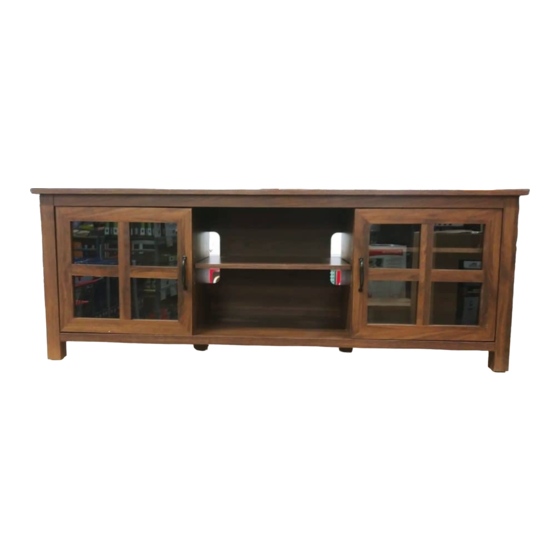
Seymour TV Console
Model # BJAVCLSM-65
ADULT ASSEMBLY REQUIRED
Pacific Standard Time: 8:30 a.m. - 4:30 p.m., Monday to Friday
www.whalenfurniture.com
Or e-mail your request to parts@whalenfurniture.com
PLEASE READ AND KEEP FOR FUTURE REFERENCE.
Date 2020-07- 24
1-866-942-5362
Rev. 0001-A
LOT NUMBER:
DATE PURCHASED: /
/
Advertisement

Related Manuals for Whalen Seymour BJAVCLSM-65


Summary of Contents for Whalen Seymour BJAVCLSM-65
- Page 1 LOT NUMBER: DATE PURCHASED: / Seymour TV Console Model # BJAVCLSM-65 ADULT ASSEMBLY REQUIRED If you have any questions regarding assembly or if parts are missing, DO NOT return this item to the store where it was purchased. Please call our toll-free customer service number and have your instructions and parts list ready to provide the model name, part name or factory number: 1-866-942-5362 Pacific Standard Time: 8:30 a.m.
- Page 2 M A X I M U M R E C O M M E N D E D W E I G H T L O A D S MANUFACTURER: Whalen Furniture Manufacturing CATALOG: Seymour TV Console MODEL # BJAVCLSM-65 FITS UP TO MOST 190.5 cm (75 in.)
- Page 3 IMPORTANT Before you begin: Open, identify and count all parts prior to assembly. Lay out parts on a flat and non- abrasive surface. You will need the parts identified on page 3 and 4 of this instruction manuals. NOTE: IT IS VERY IMPORTANT TO USE GLUE WITH THE DOWELS. EXCESS GLUE CAN BE WIPED OFF WITH A DAMP CLOTH.
- Page 4 Parts and Hardware List Please read completely through the instructions and verify that all listed parts and hardware are present before beginning assembly. A- Top Panel (Qty. 1) B-Left Side Frame (Qty. 1) C- Right Side Frame (Qty. 1) D- Left Partition Panel (Qty. 1) E- Right Partition Panel (Qty.
- Page 5 Parts and Hardware List Please read completely through the instructions and verify that all listed parts and hardware are present before beginning assembly (1) Cam Lock (2) Cam Bolt (3) M8 x 30 mm Wood Dowel (Qty. 17+1 extra) (Qty. 17+1 extra) (Qty.
- Page 6 Assembly Instructions 1. Unpack the unit and confirm that you have all the hardware and required parts. Assemble the unit on a carpeted floor or the empty carton to avoid any scratch. 2. Securely screw the Cam Bolts (2) into the designated small holes on the Top Panel (A) and both Side Frames (B and C) with a Phillips screwdriver.
- Page 7 Assembly Instructions 4. Using the wood dowels as a guide, attach the Partition Panels (D and E) to the Bottom Panel (F) and fasten them in place with four 50 mm Screws (5). Fully tighten the screws with a Phillips screwdriver. 5.
- Page 8 Assembly Instructions 6. Ask for assistance to lift the assembly upright and proceed to fasten the Top Front Stretcher (G) to both Side Frames (B and C) by engaging two Cam Locks (1). 7. Glue the Wood Dowers (3) into the top inner holes of the unit. DO NOT inert the wood dowels into the cam lock holes.
- Page 9 Assembly Instructions 8. Place the Top Panel (A) onto the inserted Wood Dowel (3) making sure the back egdes are even with each panels. Attach the Top Panel (A) in place by engaging the Cam Locks (1). 9. Now, go back and tighten all cam locks. Make sure that all the parts are tight and there are no gaps between the pieces.
- Page 10 Assembly Instructions 11. Securely screw two Center Supports (H) into the threaded inserts on the Bottom Panel (F). 12. Ask for assistance to lift the assembly unit upright. 13. Insert the Shelf Supports (10) into the desired holes in the sides of each compartment. Make sure you place the four Shelf Supports (10) in the same level so the shelf is not tilted.
- Page 11 Assembly Instructions 14. Pick up one Door (I) and attach the extended hinge arms to the hinge bases installed on the Left Side Frame (B). Loosen the bolt on the back of hinge base for an easy fit. Align and insert the “U” slot on hinge arm under the bolt head on the back of hinge base.
- Page 12 Assembly Instructions 18. Stick the Rubber Bumpers (11) at the outer corners of both Doors (I) where they meet the Partition Panels (D and E). 19. Plug Cam Lock Covers (7) onto the visible Cams Locks to conceal the cams. NOTE: To prevent your TV from tipping, you must follow these instructions if you place a TV on top of your console.
- Page 13 Assembly Instructions Tools required: Phillips screwdriver, stud finder, pencil, tape measure, power drill and 1/8” drill bit. 22. Ask for assistance to position the assemble TV stand at the desired location against a wall. If necessary, adjust the pre-attached floor levelers at the bottom of the Side Frames (B and C) and Center Supports (H) to correct the tilt and level the doors.
- Page 14 WARNING Please use your furniture correctly and safely. Improper use can cause safety hazards, or damage to your furniture or household items. Carefully read the following safety information. This unit is not intended for use with CRT TVs. The top surface maximum weight capacity is 100 lbs. (45.4 kg) and maximum load 75 in.
-
Page 15: Care And Maintenance
Should this product be defective in workmanship or materials or fail under normal use, we will repair or replace it for up to one (1) year from date of purchase. Every Whalen Furniture product is designed to meet your highest expectations. We guarantee that you will immediately see the value of our fine furniture.
Need help?
Do you have a question about the Seymour BJAVCLSM-65 and is the answer not in the manual?
Questions and answers