Advertisement
Quick Links
This item is designed to be a 3-in-1 configuration. Please choose the option that best suits your needs. DO NOT
discard any of the hardware or parts that you will not use on your chosen option. This will allow you to use this
TV Console in different configurations at a later date, if desired.
If you have any questions regarding assembly or if parts are missing, DO NOT return this item to the
store where it was purchased. Please call our toll-free customer service number and have your
instructions and parts list ready to provide the model name, part name or factory number:
Pacific Standard Time: 8:30 a.m. - 4:30 p.m., Monday to Friday
Or visit our website 24 hours a day, 7 days a week for product assistance at
THIS INSTRUCTION BOOKLET CONTAINS IMPORTANT SAFETY INFORMATION.
3-in-1 TV Stand
Model # BJXL-2
U.S. Patent 8,561,551
ADULT ASSEMBLY REQUIRED
www.whalenfurniture.com
Or e-mail your request to parts@whalenfurniture.com
PLEASE READ AND KEEP FOR FUTURE REFERENCE.
Date 2021-05-06
1-866-942-5362
Rev. 0001-A
LOT NUMBER:
DATE PURCHASED: /
TV
/
Advertisement

Subscribe to Our Youtube Channel
Related Manuals for Whalen BJXL-2


Summary of Contents for Whalen BJXL-2
- Page 1 LOT NUMBER: DATE PURCHASED: / 3-in-1 TV Stand Model # BJXL-2 U.S. Patent 8,561,551 This item is designed to be a 3-in-1 configuration. Please choose the option that best suits your needs. DO NOT discard any of the hardware or parts that you will not use on your chosen option. This will allow you to use this TV Console in different configurations at a later date, if desired.
-
Page 2: Special Note
G E N E R A L I N F O R M A T I O N , T I P S a n d T R I C K S 1. Please read the Assembly Instructions prior to assembling this product. 2. - Page 3 Parts and Hardware List Please read completely through the instructions and verify that all listed parts and hardware are present before beginning assembly. A- Top Shelf Frame (Qty. 1) B- Middle Shelf Frame (Qty. 1) C- Bottom Shelf Frame (Qty. 1) D- Lower Spine (Qty.
- Page 4 Parts and Hardware List (1) Suction Cup (2) 1/2” Bolt (3) 5/8” Bolt (4) 1 1/8” Bolt (Qty. 18+1 extra) (Qty. 4+1 extra) (Qty. 14+1 extra) (Qty. 12+1 extra) (5) Lock Washer (6) Flat Washer (7) 3-1/8” Bolt (8) Blind Nut (Qty.
- Page 5 Assembly Instructions ④ x 4 NOTE: Please do not fully tighten all bolts until you finish assembling all parts. Once assembled, go back and fully tighten all bolts. This will make the assembly easier. 1. Unpack the unit and confirm that you have all the hardware and required parts. Locate the Lower Spine (D) and set back face down on a scratch free surface.
- Page 6 Assembly Instructions ④ x 4 4. Align and attach the Left Leg (F) to the Lower Shelf Frames (B and C) by inserting two 1 1/8” Bolts (4) from inside the Shelf Frames through the pre-drilled holes on side rail and screw into the threaded sockets on the Leg.
- Page 7 Assembly Instructions ⑤ x 4 ⑥ x 4 ④ x 4 6. Stand the unit upright. 7. Align and attach the Top Shelf Frame (A) to the Legs (F and G) with the inside corner plates facing up, using four 1 1/8” Bolts (4) and four Washers (5 and 6). If you choose Table-top Console configuration, continue to the next step.
- Page 8 Assembly Instructions for Table-top Console ⑦ ⑤ x 1 ⑥ x 1 ⑧ 8. Plug the Spine End Cap (12) all the way into the top of the Lower Spine (D). 9. Secure the Top Shelf Frame (A) to the Lower Spine (D) by inserting one 3-1/8” Bolt (7) with the Washers (5 and 6) through the bracket hole and securely screw into the Blind Nut (8).
- Page 9 Assembly Instructions for Table-top Console ③ x 4 11. Attach 2 Cable Wheels (M) to the backside of the Lower Spine (D) with the 3/4” Bolts (3). Tighten the bolts with the provided hex wrench. 12. The Cable Wheels (M) enable you to shorten, separate and route cables and cords. Using the Cable Wheels, you can create a system for routing cables through channels, between components and to power sources without tangled mess or annoying signal interference.
- Page 10 Assembly Instructions for Table-top Console H/ I A/B/C ① X 18 13. Put the Suction Cups (1) firmly into top holes and metal tabs on 3 Shelf Frames (A, B and C), as shown. TIP: If a Suction Cup resists insertion, try pressing down on the middle of the cup with the hex wrench while twisting it clockwise into the hole.
- Page 11 Assembly Instructions for Table-top Console Tools required: Hex wrench (provided), Phillips screwdriver, stud finder, measure tape, pencil, power drill, and 1/8” drill Bit (not provided). 15. Position the assembled unit at the desired location against a wall. In case of uneven floor, Floor Levelers are provided at the bottom of both Legs (F and G).
- Page 12 A s s e m b l y I n s t r u c t i o n s f o r F l o a t i n g S w i v e l M o u n t ③...
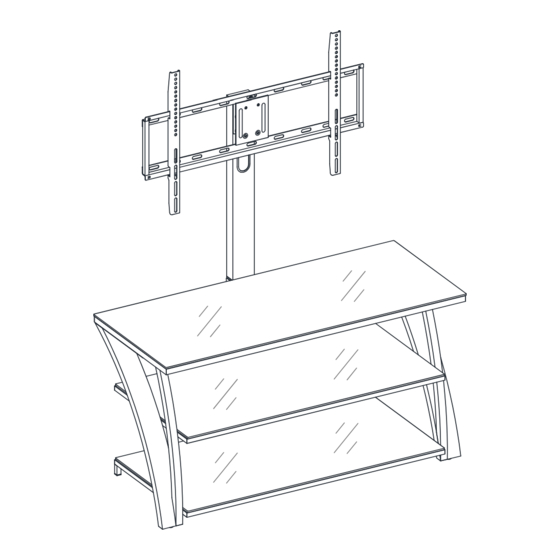
- Page 13 Assembly Instructions for Floating Swivel Mount ③ X 6 ⑤ X 6 ⑥ X 6 19. Fasten the Swiveling Bracket (J) to the top of the Upper Spine (E) with six 3/4” Bolts (3) and six Washers (5 and 6). Turn the Swiveling Bracket against the Upper Spine (E) when tightening the bolts with the enclosed hex wrench.
- Page 14 Assembly Instructions for Floating Swivel Mount ⑤ x 4 ② x 4 ⑥ x 4 20. Hold and attach the flat side of the Mounting Frame (K) onto the Swiveling Bracket (J) using four 1/2” Bolts (2) and four Washers (5 and 6). Make sure that the recess holes on the Mounting Frame are located at the bottom.
- Page 15 Mounting Monitor Brackets to a Television with a Flat Back NOTE: For televisions with a curved or recessed back, proceed directly to next page. 22. Determine the correct diameter of the bolt the TV requires by hand threading them into the threaded insert on the back of the TV.
- Page 16 Mounting Monitor Brackets to a Television with a Curved/Recessed Back 24. Determine the correct diameter of the bolt the TV requires by hand threading them into the threaded insert on the back of the TV. If you encounter any resistance, stop immediately. If you are unable to find the correct bolt consult a local hardware store.
- Page 17 Assembly Instructions for Floating Swivel Mount MAKE SURE ALL BOLTS ARE TIGHT AND THE SPINE IS AT A 90 DEGREE ANGLE AND USE A QUALITY LEVEL TO VERIFY THE MOUNTING FRAME IS LEVEL PRIOR TO INSTALLATION OF TV. 26. Once the Monitor Brackets (L) are attached onto the back of television, ask for assistance to lift the television up to hang the Monitor Brackets (L) onto the Mounting Frame (K).
- Page 18 Assembly Instructions for Floating Swivel Mount H/ I A/B/C 28. Repeat steps 13 through 14 to install the Top Glass (H) and Glass Shelves (I) in place.
- Page 19 Assembly Instructions for Floating Swivel Mount Tools required: Hex wrench (provided), Phillips screwdriver, stud finder, measure tape, pencil, power drill, and 1/8” drill Bit (not provided). 29. Carefully move the unit and position in your desired location against a wall. Now follow the instructions printed on the plastic bag containing Tipping Restraint Hardware Kit to attach the tip-over restraint to the Upper Spine (E) and the wall.
- Page 20 The following steps are only for those who wish to mount their TV directly to the wall. If you have already mounted your TV to the Swinging Floater or plan to display your TV on the top surface of the stand, disregard the following steps. Assembly Instructions for Universal Wall Mount Installing the Mounting Frame onto a WOODEN STUD WALL 407 mm...
- Page 21 Assembly Instruction for installing the Mounting Frame onto a BRICK, SOLID CONCRETE OR CONCRETE BLOCK WALL 407 mm 16 in / po 166 mm 6.5 in / po 63.5 mm 2.5 in / po Concrete Anchors should only be used for masonry mounting. NEVER use the wall anchors to mount the unit to drywall.
- Page 22 Assembly Instructions 37. Attach the Monitor Brackets (L) to the back of the television following steps 21 and 22, or 23 and 24, depending on the type of TV that you own. 38. Ask for assistance to lift the television up to attach the Monitor Brackets (L) onto the Mounting Frame (K).
-
Page 23: Care And Maintenance
Care and Maintenance For everyday cleaning, chrome, brass, aluminum, and painted metal surfaces can be kept looking their best by wiping with a slightly damp, soft cotton cloth, or vacuum cleaner brush. If soiled, wipe with clean sponge or cloth wrung out of water. Wipe dry with cloth or paper towel to avoid water spots. -
Page 24: Quality Guarantee
Should this product be defective in workmanship or materials or fail under normal use, we will repair or replace it for up to one (1) year from date of purchase. Every Whalen Furniture product is designed to meet your highest expectations. We guarantee that you will immediately see the value of our fine furniture.
Need help?
Do you have a question about the BJXL-2 and is the answer not in the manual?
Questions and answers