Advertisement
Quick Links
This smart thermostat has been developed to be able to switch electric and conventional heating systems on and off using
a set temperature and time remotely at anytime anywhere.
Technical Data
Sender Power Supply
Receiver Load current
Set Point Range
Ambient
Relative Humidity
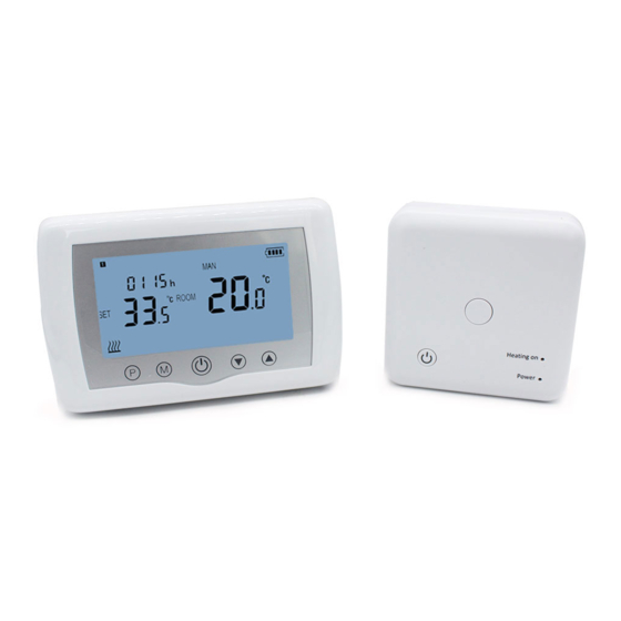
Display and Buttons
Weekday
Clock
Set Temp.
Heating Icon.
WIFI BOILER THERMOSTAT
- 2*AAA battery
- 230Vac/Max 10A
- 5~35
℃
- 0~50
℃
- 85%
PRG. Button
On/off Button
Modes Select
Backlight
-
White
Sensor
- NTC 10K, 3950ohms at 25
Accuracy
- ± 0.5
℃
(step control by +0.5
Protection Class - IP30
Housing
- ABS to UL94-5 fire retardant plastic
Temp. & Parameters setting
1
HTW-31-WKT19-WF
℃
℃
)
Battery Indicator
Room Temp. Display
Programmable Period
Advertisement

Related Manuals for HOTOWELL HTW-31-WKT19-WF


Summary of Contents for HOTOWELL HTW-31-WKT19-WF
- Page 1 WIFI BOILER THERMOSTAT HTW-31-WKT19-WF This smart thermostat has been developed to be able to switch electric and conventional heating systems on and off using a set temperature and time remotely at anytime anywhere. Technical Data Sender Power Supply - 2*AAA battery...
- Page 2 WIFI BOILER THERMOSTAT HTW-31-WKT19-WF RRG. Setting Long press P button to enter PRG setting. The weekday is fixed from Monday to Sunday(1~7), each day have 4 periods(1~4). Each press of P button can into next item setting. The time and temperature of each period i can be set in following steps.
- Page 3 WIFI BOILER THERMOSTAT HTW-31-WKT19-WF I. Code Pairing with Sender 1) Long press the code pairing button on the receiver until LED 1 is flickering quickly. 2) Long press M button unit Code display, then press up button. 3) Wait for a while, LED 1 stop flickering. Code pairing finished.
- Page 4 WIFI BOILER THERMOSTAT HTW-31-WKT19-WF Wiring Diagrams Installation and Dimension For portable use, its foot pod must be installed to control unit as can be seen in the figure below. For wall mounting, first the wall bracket should be mounted on the wall, then the control unit and the wall bracket must be fitted as shown in the following figure.
Need help?
Do you have a question about the HTW-31-WKT19-WF and is the answer not in the manual?
Questions and answers