
Related Manuals for 3M 4990


Summary of Contents for 3M 4990
- Page 1 4990 Outdoor Protected Entrance Terminals Underwriters Laboratories (UL) Listed Instructions July 2000 78-8124-8790-4-A...
-
Page 2: Table Of Contents
Contents: General ............................... 1 Accessories ............................4 Protector Specifications........................5 Tool Requirements ..........................5 Terminal Locations ..........................5 Terminal Grounding ........................... 6 Entrance Cable Preparation and Termination ..................6 Distribution Cable Termination ......................9 Protector Installation .......................... 10 10.0 Multiple Terminal Installation ......................11... -
Page 3: General
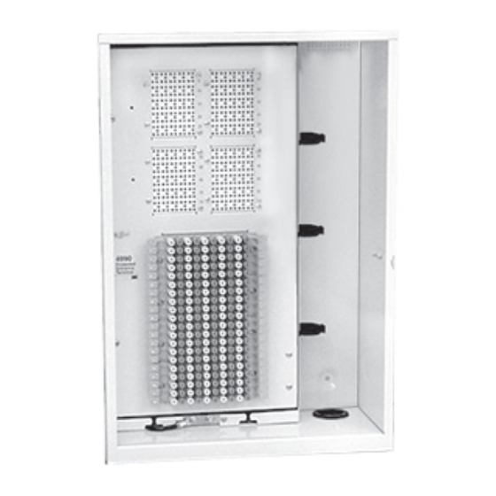
1.0 General ™ The 3M 4990 Protected Entrance Terminals (PETs) provide for the protection and termination of entrance and distribution cables. The terminals are available in 25, 50, 100, and 300 pair sizes and are Underwriter Laboratories (UL) Listed. 4990-25... -
Page 4: Accessories
7.9" 2.0 Accessories 4990-SK Skirt - The 4990-SK skirt is used with the 25, 50, and 100 pair terminals when physical protection of incoming cable is preferred or when a separate splice location below the terminal is desired. 4788-SKW Skirt - The 4788-SKW skirt is used with the 300 pair terminal when physical protection of incoming cable is preferred or when a separate splice location below the terminal is desired. -
Page 5: Protector Specifications
Note: If a 4990-SK, 4788-SKW, 4990-WB, or 4788-WBW is to be installed, these items should be installed first and then proceed to section 6.0. Open the terminal door using a 7/16" terminal wrench. Remove the door by lifting upward. Stow the door in a safe place until installation is completed. -
Page 6: Terminal Grounding
Remove excess cable. ™ Slide the 3M Pull n’ Shrink Tubing (PST) over the cable sheath with the pull tab facing away from the terminal. If installing a 25 or 50 pair cable, slide both PST tubes on, sliding the larger one on first, then the smaller one. - Page 7 Lay the cable against the housing and mark the sheath allowing for a minimum of 2” (51mm) of cable sheath to extend past the cable entry port. core 1/2" wrap (13mm) Remove the cable sheath leaving a minimum of 1/2” (13mm) of core wrap 2"...
- Page 8 7.17 Cable Termination - ™ ™ When splicing with discrete connectors such as 3M Scotchlok connectors: Using tie wraps, secure the cable groups to the slotted bracket on the left hand side of the splice chamber while maximizing slack and maintaining good housekeeping.
-
Page 9: Distribution Cable Termination
8.0 Distribution Cable Termination Cut an X shaped slit in the rubber grommet located in the lower right hand corner. Install terminal door. Route the distribution pair(s) through the grommet and up to the distribution block and locate the desired pair location on the block. -
Page 10: Protector Installation
Testing Align the 4327 single pair test probe as shown. Cap Test Ring Ports Ring Note: The test probe may be attached to either jumpered or non-jumpered caps. However, the presence of special circuit caps prevent the test probe from making contact with that specific pair. -
Page 11: Multiple Terminal Installation
If wire work is to pass between the terminals, make sure all appropriate knockouts are removed and install the plastic edging provided to eliminate chafing of the wire insulation. Place a 4990-CLR stacking collar on the top of the first terminal. Make sure that it is fully seated and in place. - Page 12 PARTICULAR PURPOSE. If this product is defective within the warranty period stated above, your exclusive remedy shall be, at 3M’s option, to replace or repair the 3M product or refund the purchase price of the 3M product. Except where prohibited by law, 3M will not be liable for any loss or damage arising from this 3M product, whether direct, indirect, special, incidental or consequential regardless of the legal theory asserted.
Need help?
Do you have a question about the 4990 and is the answer not in the manual?
Questions and answers