Advertisement
Quick Links
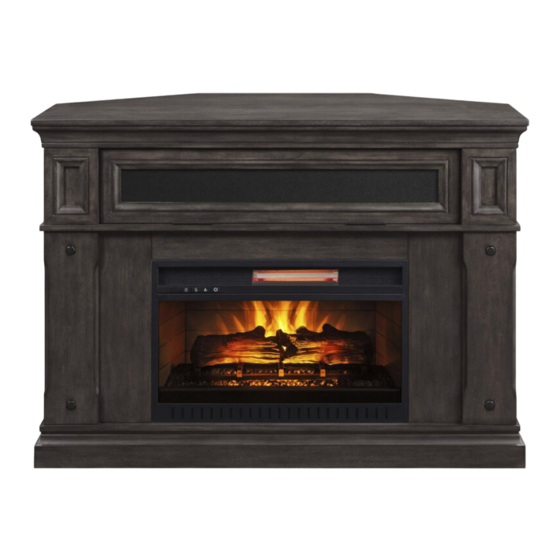
Amesville 50" Fireplace Console
If you have any questions regarding assembly or if parts are missing, DO NOT return this item to the
store where it was purchased. Please call our toll-free customer service number and have your
instructions and parts list ready to provide the model name, part name or factory number:
Or visit our web site 24 hours a day, 7 days a week for product assistance at
THIS INSTRUCTION BOOKLET CONTAINS IMPORTANT SAFETY INFORMATION.
Model # MNFP50AV26IA
ADULT ASSEMBLY REQUIRED
Pacific Standard Time: 8:30 a.m. - 4:30 p.m., Monday - Friday
www.whalenfurniture.com
Or e-mail your request to parts@whalenfurniture.com
PLEASE READ AND KEEP FOR FUTURE REFERENCE.
Date 2020-05-20
# MNFP50AV26IB
1-866-942-5362
Rev. 0001-A
LOT NUMBER:
DATE PURCHASED: /
/
Advertisement

Related Manuals for Whalen Amesville MNFP50AV26IA


Summary of Contents for Whalen Amesville MNFP50AV26IA
- Page 1 LOT NUMBER: DATE PURCHASED: / Amesville 50” Fireplace Console Model # MNFP50AV26IA # MNFP50AV26IB ADULT ASSEMBLY REQUIRED If you have any questions regarding assembly or if parts are missing, DO NOT return this item to the store where it was purchased. Please call our toll-free customer service number and have your instructions and parts list ready to provide the model name, part name or factory number: 1-866-942-5362 Pacific Standard Time: 8:30 a.m.
- Page 2 IMPORTANT Before you begin: Open, identify and count all parts prior to assembly. Lay out parts on a flat and non-abrasive surface. You will need the parts identified on page 3 and 4 of this instruction manuals. NOTE: IT IS VERY IMPORTANT TO USE GLUE WITH THE DOWELS. EXCESS GLUE CAN BE WIPED OFF WITH A DAMP CLOTH.
- Page 3 Parts and Hardware List Please read completely through the instructions and verify that all listed parts and hardware are present before beginning assembly. A- Top Panel (Qty. 1) B- Top Corner Extension (Qty. 1) C- Upper Left Side Frame (Qty. 1) D- Upper Right Side Frame (Qty.
- Page 4 Parts and Hardware List Please read completely through the instructions and verify that all listed parts and hardware are present before beginning assembly. (1) 1/4” x 15 mm Bolt (2) 1/4” x 32 mm Bolt (3) Lock Washer (Qty. 10+1 extra) (Qty.
- Page 5 Assembly Instructions NOTE: DO NOT fully tighten all bolts until you finish assembling all parts. Once assembled, go back and fully tighten all bolts. 1. Unpack the unit and confirm that you have all the hardware and required parts. Assemble the unit on a carpeted floor or the empty carton to avoid any scratch.
- Page 6 Assembly Instructions 5. Glue the Long Wood Dowels (5) into the inner holes on Lower Side Panels (H), Lower Side Moldings (I and J) and Middle Crossbar (K) as shown. 6. Using the pilot holes as a guide, attach four Mending Plates (12) to the Middle Crossbar (K) with four 12 mm Screws (6).
- Page 7 Assembly Instructions The cleats face inward 7. Align and attach the Middle Crossbar (K) to the Media Shelf (G) with two 32 mm Bolts (2) and two Washers (3 and 4). I /J/H 8. Using the wood dowels as a guide, attach the Lower Side Panels (H) and Lower Side Moldings (I and J) to the Base (L) with six 32 mm Bolts (2) and six Washers (3 and 4).
- Page 8 Assembly Instructions I /J/H 9. Place the Media Shelf (G) onto the inserted Wood Dowels (5) on the vertical panels and fasten it in place with six 32 mm Bolts (2) and six Washers (3 and 4). I /J 10. Using the pilot holes as a guide, fasten the Mending Plates (12) attached on the Middle Crossbar (K) to the Lower Side Moldings (I and J) with four 12 mm Screws (6).
- Page 9 Assembly Instructions 11. Glue the wood dowels into the inner holes on the Upper Side Frames (C and D) and Upper Partition Panels (E and F) as shown. 12. Using the pilots holes as guide, fasten the Magnetic Catches (10) to the Upper Side Frames (C and D) with two 15 mm Pan Head Screws (9) in each.
- Page 10 Assembly Instructions Plastic slides face inward 13. Place the Top Panel (A) upside down on a protected surface and attach the Upper Partition Panels (E and F) to the Top Panel (A) with four 32 mm Bolts (2) and four Washers (3 and 4). Catches face upward and inward 14.
- Page 11 Assembly Instructions 16. Attach the previous assembly to the Media Shelf (G) with four 32 mm Bolts (2) and four Washers (3 and 17. Now, go back and securely tighten all the bolts and screws. Make sure that all the parts are tight and there are no gaps between the parts.
- Page 12 Assembly Instructions The hooks point towards the strike plates 19. Using the pilot holes as a guide, fasten two Hooks (13) to the upper corners of the Barrister Door (N) with four 12 mm Screws (6) as shown. 20. Attach two Handles (11) to the Barrister Door (N) with four 15 mm Flat Head Screws (7). Wood Insert Glass Insert Speaker Grill...
- Page 13 Assembly Instructions 22. Hook the Barrister Door (N) onto the pre-attached plastic slides on the Upper Partition Panels (E and F) and tuck it underneath the Top Panel (A) in one smooth motion. 23. Lift the fireplace insert carefully into the back of the assembled mantel and center it in the opening. drag the insert across the Base (L) as it may scratch the unit.
- Page 14 Assembly Instructions 24. Using the pilot holes as a guide, fit two Metal Brackets (14) onto the side plates of the fireplace insert and fasten them into place with four 15 mm Pan Head Screws (9). 25. Attach one Connector (15) to the end of each Corner Support (M and S) with one 15 mm Bolt (1) as shown.
- Page 15 Assembly Instructions 26. Glue two Short Wood Dowels (17) into the inner holes on the Long Corner Support (M). 27. Attach the Short Corner Support (S) to the Long Corner Support (M) with three 25 mm Screws (16). 28. Attach three Connectors (15) to the Top Corner Extension (B) with three 15 mm Bolts (1).
- Page 16 Assembly Instructions 29. Attach the Long Corner Support (M) to the Top Corner Extension (B) with one 15 mm Bolt (1). 30. Align and attach the assembled Corner Extension to the Top Panel (A) and the Base (L) with four 15 mm Bolts (1).
- Page 17 Assembly Instructions Tools required (not provided): Phillips screwdriver, stud finder, tape measure, pencil, power drill and 1/8” drill bit. 31. Ask for assistance to position the assemble fireplace at the desired location against a wall. If necessary, adjust the pre-attached Floor Levelers at the Base (L) to level the unit. 32.
-
Page 18: Care And Maintenance
Care and Maintenance Use a soft, clean cloth that will not scratch the surface when dusting. Use of furniture polishes is not necessary. Should you choose to use polishes, test first in an inconspicuous area. Using solvents of any kind on your furniture may damage the finish. ... -
Page 19: Quality Guarantee
Should this product be defective in workmanship or materials or fail under normal use, we will repair or replace it for up to one (1) year from date of purchase. Every Whalen Furniture product is designed to meet your highest expectations.
Need help?
Do you have a question about the Amesville MNFP50AV26IA and is the answer not in the manual?
Questions and answers