Advertisement
Quick Links
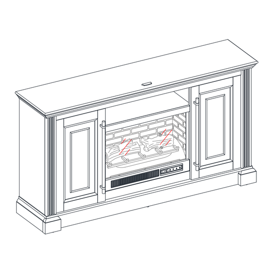
Hutchinson 65" Fireplace Console
If you have any questions regarding assembly or if parts are missing, DO NOT return this item to the
store where it was purchased. Please call our toll-free customer service number and have your
instructions and parts list ready to provide the model name, part name or factory number:
Pacific Standard Time: 8:30 a.m. - 4:30 p.m., Monday - Friday
Or visit our web site 24 hours a day, 7 days a week for product assistance at
THIS INSTRUCTION BOOKLET CONTAINS IMPORTANT SAFETY INFORMATION.
Model # MNFP65MR26HLAWT
# MNFP65MR26HLADK
ADULT ASSEMBLY REQUIRED
1-866-942-5362
www.whalenfurniture.com
Or e-mail your request to parts@whalenfurniture.com
PLEASE READ AND KEEP FOR FUTURE REFERENCE.
Date: 2024-06-12
LOT NUMBER:
DATE PURCHASED: /
OR
Rev. 0001-A
/
Advertisement

Related Manuals for Whalen Hutchinson MNFP65MR26HLAWT


Summary of Contents for Whalen Hutchinson MNFP65MR26HLAWT
- Page 1 LOT NUMBER: DATE PURCHASED: / Hutchinson 65” Fireplace Console Model # MNFP65MR26HLAWT # MNFP65MR26HLADK ADULT ASSEMBLY REQUIRED If you have any questions regarding assembly or if parts are missing, DO NOT return this item to the store where it was purchased. Please call our toll-free customer service number and have your instructions and parts list ready to provide the model name, part name or factory number: 1-866-942-5362 Pacific Standard Time: 8:30 a.m.
- Page 2 IMPORTANT Before you begin: Open, identify and count all parts prior to assembly. Lay out parts on a flat and non-abrasive surface. You will need the parts identified on page 3, 4 and 5 of this instruction manuals. NOTE: IT IS VERY IMPORTANT TO USE GLUE WITH THE DOWELS. EXCESS GLUE CAN BE WIPED OFF WITH A DAMP CLOTH.
- Page 3 Parts and Hardware List Please read completely through the instructions and verify that all listed parts and hardware are present before beginning assembly. A- Heater B- Left Upright Arm C- Right Upright Arm (Qty. 1) (Qty. 1) (Qty. 1) D- Connector Strap E- Ember Bed F- Left Log (Qty.
- Page 4 Parts and Hardware List Please read completely through the instructions and verify that all listed parts and hardware are present before beginning assembly. S- Left Side Panel T- Left Partition U- Right Partition (Qty. 1) (Qty. 1) (Qty. 1) V- Right Side Panel W- Media Shelf X- Door (Qty.
- Page 5 Parts and Hardware List Please read completely through the instructions and verify that all listed parts and hardware are present before beginning assembly. (1) M4 x 10 mm Insert Screw (2) Cam Lock (3) Cam Bolt (Qty. 10+1 extra) (Qty. 38+1 extra) (Qty.
- Page 6 Assembly Instructions 1. Unpack the unit and confirm that you have all the hardware and required parts. Assemble the unit on a carpeted floor or the empty carton to avoid any scratch. 2. Securely screw 14 Cam Bolts (3) into the designated small holes on the Top Panel (K) and Side Panels (S and V) with a Phillips screwdriver.
- Page 7 Assembly Instructions The wood dowels face upward. The cam lock housings face inward. 4. Orient and attach the Top Stretcher (L) between the Side Panels (S and V) by engaging and tightening 2 Cam Locks (2) with a Phillips Screwdriver. (Refer to page 2 on Cam Lock system operation supplement).
- Page 8 Assembly Instructions 6. Securely screw 4 Cam Bolts (3) into the designated small holes on the Partitions (T and U) with a Phillips screwdriver. Correct Incorrect 7. Glue 12 Wood Dowels (4) into the designated holes on both Partitions (T and U) and the Media Shelf (W).
- Page 9 Assembly Instructions The molding is located at the front. The cam lock housings face inward. 8. Orient and attach the Media Shelf (W) between the Partitions (T and U) by engaging and tightening 4 Cam Locks (2). 9. Align and attach the previous assembly to the Top Panel (K) by engaging and tightening 4 Cam Locks (2).
- Page 10 Assembly Instructions 10. Securely screw 11 Cam Bolts (3) into the designated small holes on the Bottom Panel (M) with a Phillips screwdriver. 11. Securely screw 5 Cam Bolts (3) into the designated small holes on the Front Skirting(N) and Side Skirtings (P) with a Phillips screwdriver.
- Page 11 Assembly Instructions Incorrect Correct 12. Glue 14 Wood Dowels (4) into the designated holes on the Skirting Boards (N, O and P) and Bottom Middle Stretcher (R). 13. Align and attach the Bottom Middle Stretcher (R) to the Front Skirting (N) by engaging one Cam Lock (2).
- Page 12 Assembly Instructions The wood dowels face upward. 14. Orient and attach the Rear Skirting (O) to the Bottom Middle Stretcher (R) by inserting two 50 mm Pan Head Screws (8) through the counter-sunk holes on the Rear Skirting (O) and securely screw into place. 15.
- Page 13 Assembly Instructions 180° 16. Align and attach the previous assembly to the Bottom Panel (M) by engaging 11 Cam Locks (2). 180° 17. Securely screw 4 Cam Bolts (3) into the designated small holes on the top of the Bottom Panel (M) using a Phillips screwdriver.
- Page 14 Assembly Instructions Correct 18. Glue 6 Wood Dowels (4) into the inner holes on the Firebox Supports (C1 and D1) as shown. 90° 19. Align the wood dowels inserted under the Firebox Short Supports (D1) with the holes on the Bottom Panel (M), and then press them together.
- Page 15 Assembly Instructions The mounting holes face inward. 20. Orient and attached the Firebox Long Support (C1) to the Bottom Panel (M). 21. Insert three 50 mm Pan Head Screws (8) through the mounting holes on the Bottom Panel (M) and securely screw into the Firebox Long Support (C1).
- Page 16 Assembly Instructions 23. Insert four 50 mm Pan Head Screws (8) through the mounting holes on the Bottom Panel (M) and securely screw into the Partitions (T and U). 180° 24. Ask for assistance to flip around the previous assembly at its front edges. 25.
- Page 17 Assembly Instructions 26. Now, go back and securely tighten all the cam locks and screws. Make sure that all the parts are tight and there are no gaps between the parts. This will help keep the unit square. 27. Pick up the Middle Back Panel (A1) and align the pre-drilled holes against the upper long edge of the pilot holes on the back of Top Panel (K).
- Page 18 Assembly Instructions 33. Extend two Door Hinges (E1) and rest the hinge cups onto the cutouts of each door (X). Secure the Door Hinges (E1) in place by using two 15 mm Screws (9) in each hinge. 34. Using pilot holes as a guide, attach one Handle (F1) to the front of each Door (X) with two 22 mm Bolts (10).
- Page 19 Assembly Instructions Depth Adjustment Vertical Adjustment Oval hole Horizontal Adjustment Round hole 35. Pick up one Door (X) and attach the installed Door Hinges (E1) to the hinge supports pre-attached on the Left Side Panel (S), using the pilot holes as a guide. Turn four 15 mm Screws (9) a few turns through the CENTERS of the oval holes in the hinges.
- Page 20 Assembly Instructions Figure A Figure B IMPORTANT NOTE: Use hand screwdriver, not power driver to assemble fireplace insert. See BILT for video instructions. 41. See figure A: Fasten upper 2 Insert Screws (1) through the Upright Arm (C) into the Heater (A) until tight.
- Page 21 Assembly Instructions USB cable 48. Set the Ember Bed (E) onto the Heater (A) as shown. 49. Push ember bed forward against the front flange of heater. 50. Position the USB cable as shown. U-channels 51. Fold the Wall Panel (H) as shown. Then position yourself at back side of Heater (A). 52.
- Page 22 Assembly Instructions 55. Fully plug the USB connector of the Ember Bed (E) into the back port of Heater (A). The warning labels on glass should face outward. 56. Slide the Glass (I) into the inner U-channels on both Upright Arms (B and C) until the glass sits onto the Heater (A).
- Page 23 Assembly Instructions The bevel edge faces inside the unit. 57. Position Top Connector Strap (D) over the Glass (I) and Upright Arms (B and C). Follow orientation shown above. 58. Fasten Connector Strap (D) to both Upright Arms (B and C) using two Insert Screws (1) as shown above.
- Page 24 Assembly Instructions 59. The firebox is now ready for the next assemble step. 60. Lift the fireplace insert carefully into the back of the assembled mantel and centre it on the bottom panel in the opening. 61. Use the pilot holes as a guide, fasten two L-Shaped Metal Brackets (12) onto the Firebox Holder (Q) with four 12 mm Pan Head Screws (11).
- Page 25 Assembly Instructions NOTE: To prevent your TV from tipping, you must install the acrylic TV stopper if you place a flat panel television on the top panel. Otherwise, skip to next step. 63. Remove the paper backing of Acrylic Stopper (14), then properly align the acrylic stopper into the cutout on the acrylic stopper template on the front of the Top Panel (K).
- Page 26 Assembly Instructions Wall Wooden stud Long screw Wall Wall Metal bracket Short screw Connector Wall Steel cable Floor leveler Tools required (not provided): Phillips screwdriver, stud finder, tape measure, pencil, power drill and 1/8” drill bit. 67. Ask for assistance to position the assembled fireplace at the desired location against a wall. If necessary, adjust the floor levelers to correct the tilting and level the doors.
-
Page 27: Care And Maintenance
Care and Maintenance Use a soft, clean cloth that will not scratch the surface when dusting. Use of furniture polishes is not necessary. Should you choose to use polishes, test first in an inconspicuous area. Using solvents of any kind on your furniture may damage the finish. ... -
Page 28: Quality Guarantee
Should this product be defective in workmanship or materials or fail under normal use, we will repair or replace it for up to one (1) year from date of purchase. Every Whalen Furniture product is designed to meet your highest expectations. We guarantee that you will immediately see the value of our fine furniture.
Need help?
Do you have a question about the Hutchinson MNFP65MR26HLAWT and is the answer not in the manual?
Questions and answers