Advertisement
Quick Links
1.
Scope
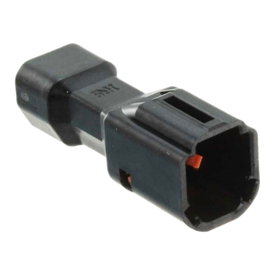
This document specifies the steps from crimping the DF62W-series crimped terminals to
cables (AWG20 to AWG30) to inserting the terminals to crimping sockets,and inserting the
terminal into the crimp case, and the procedure for mounting the panel of the DF62WP
series.
2.
Connectors
Crimping cases
DF62W # – EP – 2.2 C
Name: DF62W
Wire seal
#=None or A to E
No. of poles: 2 to 9
Connector types
S : Socket
EP: In-line plug
Contact pitch: 2.2 mm
❻
Shape of connection/terminal
C
: Crimping case
Crimping cases (Panel waterproof type)
4
DF62WP – */*/*/* EP – 2.2 C
Name: DF62WP
No. of poles: 2 to 9
" /" Indicates that the connector is a
composite connector with a number of
poles separated by it.
Connector types
EP: In-line plug
Contact pitch: 2.2 mm
Shape of connection/terminal
C
: Crimping case
Water proof pin
DF62W – WP
Application
WP: Waterproof pin
COUNT
DESCRIPTION OF REVISIONS
4
12
TITLE
DF62W Series Cable Assembly Procedure
4
DF62WP series panel installation procedure
TECHICAL SPECIFICATION
FORM HC0011-9-1
❻
DIS-H-00006326
DESIGNED
KI.SUGAWARA
HIROSE ELECTRIC CO.,LTD.
APPROVED
CHECKED
DESIGNED
WRITTEN
ETAD-H0760
CHECKED
DATE
ST.WADA
20201006
KI.AKIYAMA
20140215
OM.MIYAMOTO
20140214
KT.ISHII
20140213
KT.ISHII
20140213
4
1 / 17
Advertisement

Related Manuals for HRS DF62W Series


Summary of Contents for HRS DF62W Series
- Page 1 Application WP: Waterproof pin COUNT DESCRIPTION OF REVISIONS DESIGNED CHECKED DATE DIS-H-00006326 KI.SUGAWARA ST.WADA 20201006 TITLE HIROSE ELECTRIC CO.,LTD. DF62W Series Cable Assembly Procedure APPROVED KI.AKIYAMA 20140215 CHECKED OM.MIYAMOTO 20140214 DF62WP series panel installation procedure DESIGNED KT.ISHII 20140213 WRITTEN KT.ISHII...
- Page 2 Crimped terminals DF62W – EP 2226 PCF A Application EP: In-line Compatible cables 2022: AWG20 to 22 2226: AWG22 to 26 2830: AWG28 to 30 Shape/packing SCF : Socket terminal, reeled SC : Socket terminal, separate PCF : Plug terminal, reeled PC : Plug terminal, separate ...
- Page 3 Steps for harnessing 3.1. Cable stripping Strip cables in accordance with Crimping Quality Standards (ATAD-H0762/0763). In so doing, make sure there is no scratch on cable cores. 3.2. Crimping Crimped terminals to cables using an applicator (AP105-DF62W-**), and check the crimping height and shape in accordance with the Table of crimping conditions and Crimping Quality Standards (ATAD-H0762/0763).
- Page 4 Insert the crimped terminal to pass through the hole of wire seal. Hole of wire seal Hole of wire seal Figure 3-2. Terminal insertion To maintain performance reliability,insert the crimp terminal straight. Horizontal insertion Tilted insertion Figure 3-3. Prohibition of diagonal insertion HIROSE ELECTRIC CO.,LTD.
- Page 5 Check that the lance of a crimping socket has been caught at the lance holder of a crimped terminal. (Slightly pull the terminal to check.) *To remove the crimped terminal halfway through insertion, pull the cable while pressing wire seal to prevent coming off. Target (5.85 mm) Target (5.55 mm) In-line plug lance...
- Page 6 For insertion, place the crimped terminal and crimping socket lock in the following direction. Lock: Right side Figure 3-6. Terminal orientation (DF62WP) Lance holder: Upper To maintain performance reliability,insert the crimp terminal straight. Horizontal insertion Tilted insertion Figure 3-7. Prohibition of diagonal insertion (DF62WP) Do not mistake the terminal hole.
- Page 7 Check that the lance of a crimping socket has been caught at the lance holder of a crimped terminal. (Slightly pull the terminal to check.) *To remove the crimped terminal halfway through insertion, pull the cable while pressing wire seal to prevent coming off. Target (1.7 mm) In-line plug lance Crimped terminal...
- Page 8 No orientation Direction of insertion Direction of insertion This surface is waterproof surface, so take care not to damage the surface. Figure 3-11. Orientation of waterproof pins To maintain performance reliability, insertion insert the waterproof pin straight. Horizontal insertion Tilted insertion ...
- Page 9 Insert a waterproof pin until it touches crimping socket. *Insertion more than the target dimension could cause degradation of waterproof performance. *To insert the waterproof pin over the target dimension, it has the possibility to fall to a low level of waterproof. Target (1.85 mm) Target (1.55 mm) To tap the waterproof pin to socket.
- Page 10 Insert the removing jig along the lance of crimping socket. (Check the appearance with the hand lens.) Direction of insertion Direction of insertion Direction of insertion Direction of insertion Figure 3-15. Repair of crimp terminals ② Additionally insert the removing jig to push up the socket lance. Keep the lance position and pull the cable.
- Page 11 Steps for mounting the panel of the DF62WP series 4.1. Mounting the panel 4.1-a. Panel insertion Align the connector using the screw holes on the panel side as a guide. Insert the connector as far as it will go while maintaining the aligned position. * The shape of the panel is an example.
- Page 12 Since the connector may be damaged or the waterproof seal may be broken, insert the connector straight into the panel and attach it. Horizontal insertion Tilted insertion Figure 4-3. Prohibition of diagonal insertion 4.1-b. Fixed with screws Install the screws with the connector fully inserted. At this time, do not fix the screws when the connector is biased in either the vertical or horizontal direction or when an excessive load is applied.
- Page 13 4.2. Remove from panel 4.2-a. Removing screws Remove screws. Figure 4-5. Removing Screw 4.2-b. Removing the connector Remove the connector from the panel. At this time, push the connector mating surface side to remove it. Do not pull the cable to remove it as it may cause the terminal to come off.
- Page 14 5. Notes *Packing and storage To pack or store assemblies, make sure overlapped connectors will not apply extreme load to the lack section. If load is applied to the lock section under high temperature and humidity for a long period of time, the lock section will be deformed which could lead poor fitting.
- Page 15 Min:30mm Min:30mm Straight Min:30mm Min:30mm Bending with a straight Sudden bending, tense bending part Figure 5-2. Cable bending (DF62WP) HIROSE ELECTRIC CO.,LTD. ETAD-H0760 15 / 17 FORM HC0011-9-2...
- Page 16 ●Cable bunding When bundling cables, prepare a part that is straight from the end face of the connector as shown in the figure below, and tie it at least 30 mm away from the end face of the connector. Do not bind near the end face of the connector because it will put a load on the terminal contact part and the terminal crimping part and cause contact failure and waterproof failure.
- Page 17 Please crimp with the terminal direction aligned. If the terminal direction is not allinged, it is necessary to rocate the terminal and insert into the crimping case. It could cause loosing the contact by stress The terminals are aligned The terminals are not aligned Figure 5-4.
Need help?
Do you have a question about the DF62W Series and is the answer not in the manual?
Questions and answers