Table of Contents
Advertisement
Quick Links
Advertisement
Table of Contents

Subscribe to Our Youtube Channel
Related Manuals for HRS Hirose IT3


Summary of Contents for HRS Hirose IT3
- Page 1 IT3/IT5 Connector System SSEMBLY OTES Document Number: ETAD-F0458 Revision 3.10 Hirose IT3/IT5 ™ Connector System Winner of 2009 SMT Vision Award PWB A ENERAL NFORMATION ESIGN OT ES SSEM BLY OT ES SMT A IPS FOR SSEMBL Y YST EM...
-
Page 2: Table Of Contents
IT3/IT5 Connector System ABLE OF ONTENTS Document Number: ETAD-F0458 Revision 3.10 Section Title Page Introduction Purpose Scope Applica tion and Interpreta tion General Information Component Weights Differences between IT3 and IT5 Connector Pa rts Pa rt Number Designation Manufa cturing Lot Number Recepta cle General Dimensions PWB Design Information Component Footprint... - Page 3 IT3/IT5 Connector System ABLE OF ONTENTS Document Number: ETAD-F0458 Revision 3.10 Al terna ti ve Alloys 7.10 Metal Cap Removal Cleaning Wa ter Washable Solder Process Saponi fiers No-Clean Solder Process Cleanliness Tes ting Inspection Sampling Frequency X-Ra y La minography Visual Inspection X-Ra y Anal ysis and Voiding Trans mission 2-Dimensional X-Ra y...
- Page 4 IT3/IT5 Connector System OCUMENT ISTORY Document Number: ETAD-F0458 Revision 3.10 Revision Description (Major changes) Date Ini tial release April 6, 2009 Revised spa cer and nut ti ghteni ng informati on Ma y 18, 2009 Revised informa tion on 300 positi on recepta cles to Augus t 26, 2009 include metal s tiffening ca p Revised s ta ck hei ght cha rts , press force informa tion and...
-
Page 5: Introduction
This technical bulletin is intended to provide basic information and product features of the Hirose IT3/IT5 BGA connector system. By providing this information, Hirose believes it can help its customers to speed product development, improve quality and reliability, and limit overall system costs. -
Page 6: Application And Interpretation
IT3/IT5 Connector System ENERAL NFORMATION Document Number: ETAD-F0458 Revision 3.10 1.3 Application and Interpretation This technical bulletin is intended to offer only general guidance and design concepts to customers. Therefore, it does not limit customer designs nor guarantee results under all situations. -
Page 7: General Information
IT3/IT5 Connector System ENERAL NFORMATION Document Number: ETAD-F0458 Revision 3.10 Section 2 General Information Hirose’s IT3/IT5 connector system is designed to provide modular high-speed differential, single-ended and power connections between two parallel boards. The interconnection to the PWBs utilizes process-friendly Ball Grid Array receptacles, while the stacking height of 15 to 40mm for IT3 and 18 to 40mm for IT5 is set by an impedance-controlled interposer that is added at the system level. -
Page 8: Component Weights
IT3/IT5 Connector System ENERAL NFORMATION Document Number: ETAD-F0458 Revision 3.10 2.1 Component Weights IT3 D-100S-BGA IT3 D-300S-BGA Receptacle will IT3 Mating accept any available Receptacle stacking height Contact Positions Part Number Weight 2.5 g (100 signals/90 grounds) IT3D-100S-BGA(**) 4.7 g (200 signals/180 grounds) IT3D-200S-BGA(**) 9.0 g... - Page 9 IT3/IT5 Connector System ENERAL NFORMATION Document Number: ETAD-F0458 Revision 3.10 IT5 +1mm Mating Receptacle Contact Positions Part Number Weight 3.5 g (100 signals/110 grounds) IT5HD-100S-BGA(**) 6.7 g (200 signals/220 grounds) IT5HD-200S-BGA(**) 12.8 g (300 signals/330 grounds) IT5HD-300S-BGA(**) * Receptacle will accept any available stacking height Mounting Receptacle Contact Positions...
- Page 10 IT3/IT5 Connector System ENERAL NFORMATION Document Number: ETAD-F0458 Revision 3.10 IT3/IT5-100P-18H IT3/IT5-200P-18H IT3/IT5-300P-18H IT3/IT5 Interposer IT3/IT5-100P-38H IT3/IT5-200P-38H IT3/IT5-300P-38H IT3 Interposer Height Variation * Components listed in gray letters a re under development Page 6 of 73...
- Page 11 IT3/IT5 Connector System ENERAL NFORMATION Document Number: ETAD-F0458 Revision 3.10 IT5 Interposer Height Variation IT3M-100P-15BGA IT3M-200P-15BGA IT3M-300P-15BGA IT3 Plug * Components listed in gray letters a re under development Page 7 of 73...
-
Page 12: Differences Between It3 And It5 Connector Parts
IT3/IT5 Connector System ENERAL NFORMATION Document Number: ETAD-F0458 Revision 3.10 2.2 Differences between IT3 and IT5 Connector Parts The differences between IT3 and IT5 receptacles are the following. Housing design is different (its outlines IT3 receptacles have latches on sides defined in white for emphasis). -
Page 13: Part Number Designation
IT3/IT5 Connector System ENERAL NFORMATION Document Number: ETAD-F0458 Revision 3.10 2.3 Part Number Designation Receptacle Interposer ITxxx - xxx S – (xx) ITxxx - xxx P – (xx) (1)(2) (3) (4) (1)(8) (3) (4) (10) Plug ITxMx - xxx P – xxBGA (xx) (1)(2) -
Page 14: Manufacturing Lot Number
IT3/IT5 Connector System ENERAL NFORMATION Document Number: ETAD-F0458 Revision 3.10 (57): Eutectic Solder: Sn (63) Pb (37) Contact Area: Gold(0.76 μm)+Ni(1.5 μm) (Receptacle only) housing color: black (59): Eutectic Solder: Sn (63) Pb (37) Contact Area: Gold(0.76 μm)+Ni(1.5 μm) (Receptacle only) housing color: gray (8) Interposer type Blank: Standard;... -
Page 15: Receptacle General Dimensions
IT3/IT5 Connector System ENERAL NFORMATION Document Number: ETAD-F0458 Revision 3.10 2.5 Receptacle General Dimensions These dimensions are the same with IT3 and IT5 standard receptacles. Dimensions A, B, D, and E are the same for standard and +1mm receptacles. Interposer and Plug Outlines Shown: 200 position mounting Shown: 200 position mounting... -
Page 16: Pwb Design Information
Revision 3.10 Section 3 PWB Design Information The Hirose IT3/IT5 connector’s footprint is a staggered area array that allows space for easy via placement and signal routing between pads. Each row of I/O’s alternates signal and ground interconnections. It is mounted to the board as a lightweight receptacle, and an interposer is used to connect to parallel PWBs at many different height options. - Page 17 IT3/IT5 Connector System ESIGN OTES Document Number: ETAD-F0458 Revision 3.10 3.1 Footprint Pad specification: 0.6mm diameter Non-Solder Mas k Defined (NSMD), also known as copper defined or metal defined, pads a re recommended. Recommended sizes and clearances a re shown below. Φ0.7 Solder Mask Aperture HIROSE...
-
Page 18: Component Footprint
IT3/IT5 Connector System ESIGN OTES Document Number: ETAD-F0458 Revision 3.10 PWB pad finish is typi call y Organic Solderability Preservative (OSP) or Hot Air Solder Level (HASL), but the component can also be used with Electroless Nickel-Immersion Gold (ENIG), Immersion Sil ver a nd Immersion Tin. The stencil apertures should be 0.54mm circles, concentri c wi th the copper pads . - Page 19 IT3/IT5 Connector System ESIGN OTES Document Number: ETAD-F0458 Revision 3.10 Mating Receptacle – IT3 IT3 D-***S-BGA Footprint Mounting Receptacle – IT5(H) IT5 M-***S-BGA Footprint * All dimensions s hown are in mm. Page 15 of 73...
- Page 20 IT3/IT5 Connector System ESIGN OTES Document Number: ETAD-F0458 Revision 3.10 Mating Receptacle – IT5(H) IT5 D-***S-BGA Footprint * All dimensions s hown are in mm. Dimension (mm) 15.75 33.25 50.75 28.10 45.60 63.10 30.10 47.60 65.10 The di fferences between IT3 and IT5 footprints a re: 1.
- Page 21 IT3/IT5 Connector System ESIGN OTES Document Number: ETAD-F0458 Revision 3.10 Polarity: Ea ch recepta cle and interposer has one corner chamfered to i nsure proper orientation during assembl y and installation. The corner wi th the chamfer is nearest to pin A1. Mating Receptacle –...
-
Page 22: Multi-Connector Systems
IT3/IT5 Connector System ESIGN OTES Document Number: ETAD-F0458 Revision 3.10 3.2 Multi-Connector Systems The IT3/IT5 connectors can be used singularly or in combination with other IT3/IT5 connectors. If multiple connectors a re used on the same PWB, they mus t be oriented in the same di rection, as shown below: Correct Orientations It is not recommended to mi x orienta tions :... -
Page 23: Spacers
IT3/IT5 Connector System ESIGN OTES Document Number: ETAD-F0458 Revision 3.10 3.3 Spacers Spa cers a re requi red to support the PWB’s and protect the BGA solder joints . Sugges ted spa cer s tyle is shown at lower right. Stacking Height Spacer, male-male, M3 thread... -
Page 24: Clearance Between Connectors
IT3/IT5 Connector System ESIGN OTES Document Number: ETAD-F0458 Revision 3.10 Recommended Spacer Location 10 - Two spacers located diagonally are 50mm minimally required. Some applications may require four spacers. 10 - Spacers should be located 10 – 50 mm 50mm from the corners of the receptacles to prevent excessive mechanical loading on the interconnections. - Page 25 IT3/IT5 Connector System ESIGN OTES Document Number: ETAD-F0458 Revision 3.10 Interposer Outline Socket Combinations Connector Minimum Pitch (mm) Connector Maximum Pitch (mm) All combi nations 31.00 209.20 Suggested clearances are based on accessibility to grip interposer for purposes of disassembly and field replacement.
-
Page 26: Interposer Direction
IT3/IT5 Connector System ESIGN OTES Document Number: ETAD-F0458 Revision 3.10 3.5 Interposer Direction Do not mix ma ting and mounting recepta cles on the same PWB. All interposers must engage in the same direction, as shown below: Correct Method – all connectors mate in same direction Incorrect Method –... -
Page 27: Alignment Tolerances
IT3/IT5 Connector System ESIGN OTES Document Number: ETAD-F0458 Revision 3.10 3.6 Alignment Tolerances Mounting Tolerances of ± 0.05mm a re requi red for robus t SMT assembl y a nd to ensure proper ma ting fi ts in cases of mul tiple connectors : Global fiducial X +/- 0.05 Y +/- 0.05... -
Page 28: Introduction To Assembly
Revision 3.10 Section 4 Introduction to Assembly The Hirose IT3/IT5 BGA Connector System is fully compatible with a wide range of SMT equipment, and can be assembled on nearly any production line without requiring special tooling or machinery. The connector receptacle’s printing and placement characteristics are similar to 1.0mm BGA devices, and its low profile, open body design opens the reflow window. -
Page 29: Stencil Design
IT3/IT5 Connector System PWB A SSEMBLY OTES Document Number: ETAD-F0458 Revision 3.10 5.2 Stencil Design The suggested PWB pad design is non-solder mask defined 0.6mm diameter circles, patterned as shown in section 3.1. A 0.54mm circular stencil aperture is recommended to correspond to the 0.6mm pad. -
Page 30: Paste Print Quality
IT3/IT5 Connector System PWB A SSEMBLY OTES Document Number: ETAD-F0458 Revision 3.10 5.4 Paste Print Quality Aperture diameters can be enlarged to accommodate other process considerations, particularly if the printing process is well controlled. Solder deposits should be of uniform size and shape, with good definition. -
Page 31: Pick And Place
Revision 3.10 Section 6 Pick and Place All Hirose IT3/IT5 standard receptacles are 6mm tall and IT5H +1mm receptacles are 7mm tall. They require no special modifications to vision or placement routines to accommodate differrent component heights if using all standard or +1mm receptacles. They are shipped in JEDEC trays with pick and place tape attached on 100 and 200 position receptacles, and metal cap attached on 300 position receptacles. -
Page 32: Media Trays
IT3/IT5 Connector System PWB A SSEMBLY OTES Document Number: ETAD-F0458 Revision 3.10 6.2 Media Trays IT3/IT5 receptacle components are shipped with pick and place tape attached, in JEDEC hard trays as shown below. IT3/IT5 JEDEC Tray for 100 Position Receptacles IT3/IT5 JEDEC Tray for 200 Position Receptacles... -
Page 33: Pre-Bake
IT3/IT5 Connector System PWB A SSEMBLY OTES Document Number: ETAD-F0458 Revision 3.10 IT3/IT5 JEDEC Tray for 300 Position Receptacles * All dimensions shown are in mm. The difference between IT3 and IT5 receptacle trays is that IT5 trays are gray-colored. 6.3 Pre-bake The connector body materials do not absorb water from the atmosphere;... -
Page 34: Component Weight
IT3/IT5 Connector System PWB A SSEMBLY OTES Document Number: ETAD-F0458 Revision 3.10 For IT3 series, the 300 position receptacle has a metal cap that is easy to remove after reflow, as shown in Section 7.10. The 200 and 100 position receptacles have adhesive tape which has a 3mm margin without adhesive for easy removal. -
Page 35: Placement Force
IT3/IT5 Connector System PWB A SSEMBLY OTES Document Number: ETAD-F0458 Revision 3.10 6.7 Placement Force Placement force should be adequate to firmly position component in solder paste without grossly deforming deposits. For best results, balls should be approximately ⅓ to ½ the depth of the solder paste. -
Page 36: Reflow Processing
Revision 3.10 Section 7 Reflow Processing The low profile design of the Hirose IT3/IT5 connector receptacles has relatively low thermal mass and provides open pathways to allow efficient heat transfer to the interconnections. The package provides low temperature differentials between interior and exterior solder joints, and between the interconnections and the package body. -
Page 37: Reflow Profile Considerations
IT3/IT5 Connector System PWB A SSEMBLY OTES Document Number: ETAD-F0458 Revision 3.10 7.3 Reflow Profile Considerations 7.4 Suggested Thermal Profile Ranges Reflow Profile Max Body Temp Max Peak Temp Reflow Min Peak Temp Melting Point Min Soak Temp Time, typically 3 to 7 minutes total Different solder pastes have different thermal performance characteristics. -
Page 38: Nitrogen Environment
IT3/IT5 Connector System PWB A SSEMBLY OTES Document Number: ETAD-F0458 Revision 3.10 7.6 Nitrogen Environment The use of nitrogen to inert the reflow process can: 1. improve solder wetting by limiting oxidation on metal surfaces 2. allow lower peak temperatures and/or lower times above liquidus 3. -
Page 39: Alternative Alloys
IT3/IT5 Connector System PWB A SSEMBLY OTES Document Number: ETAD-F0458 Revision 3.10 7.9 Alternative Alloys BGA ball alloys other than SnPb or SAC305 may be available. Contact Hirose for more information. 7.10 Cap Removal The metal cap is secured onto the 300 pos receptacle with four small latches that are located on either side of the lifting tabs. - Page 40 IT3/IT5 Connector System PWB A SSEMBLY OTES Document Number: ETAD-F0458 Revision 3.10 Lift upward on one side while holding the other side in place. Precaution: It is important to “roll” the cap off the connector gently. It is designed to separate very easily with this method.
-
Page 41: Cleaning
IT3/IT5 Connector System PWB A SSEMBLY OTES Document Number: ETAD-F0458 Revision 3.10 Section 8 Cleaning The IT3/IT5 connector system receptacle’s post-reflow standoff height of 0.8 mm and open body design make it very easy to clean solder paste residues, even with modest cleaning processes. -
Page 42: Saponifiers
IT3/IT5 Connector System PWB A SSEMBLY OTES Document Number: ETAD-F0458 Revision 3.10 8.2 Saponifiers All solder pastes that are classified as water soluble or water washable may be cleaned effectively with hot water alone, but their solubility greatly improves if saponifiers are added to the cleaning bath. -
Page 43: Cleanliness Testing
IT3/IT5 Connector System PWB A SSEMBLY OTES Document Number: ETAD-F0458 Revision 3.10 8.4 Cleanliness Testing Ionic cleanliness cannot be confirmed visually. The absence of visible residues does not indicate complete cleanliness. Ionograph or ion chromatography tests must be used to verify cleanliness and fitness for use. -
Page 44: Inspection
Revision 3.10 Section 9 Inspection The Hirose IT3/IT5 receptacles’ 6mm or 7mm heights allow for high-resolution, low-noise x-ray imaging. Whether a mounting or mating receptacle, and regardless of the stacking height of the final assembly, the images remain consistent. No special modifications to the image analysis routine to compensate for different connector heights are needed. -
Page 45: X-Ray Analysis And Voiding
IT3/IT5 Connector System PWB A SSEMBLY OTES Document Number: ETAD-F0458 Revision 3.10 9.4 X-Ray Analysis and Voiding Levels of acceptability for voiding depend on the final application of the end product. For general guidelines regarding voiding, see IPC-7095, Design and Assembly Process Implementation for BGA’s. -
Page 46: Automatic Inspection Optimization
IT3/IT5 Connector System PWB A SSEMBLY OTES Document Number: ETAD-F0458 Revision 3.10 9.6 Automatic Inspection Optimization See flowchart below for optimizing inspection routines: Optical Inspection Inspect Solder Perform BGA Using Hand-held Joint Attachment Rework Mirrors or Endoscope via 2D X-ray Solder Defect Solder Defect Detected via 3D... -
Page 47: Rework
IT3/IT5 Connector System PWB A SSEMBLY OTES Document Number: ETAD-F0458 Revision 3.10 Section 10 Rework Rework processing of the IT3/IT5 connector receptacle is similar to that of other high-value BGA devices. Thermal profiles should be developed specifically for the receptacle, best available practices should be used for site redressing, and receptacles that are removed from PWB’s should be discarded and not reused. -
Page 48: Reflow Profile Considerations
IT3/IT5 Connector System PWB A SSEMBLY OTES Document Number: ETAD-F0458 Revision 3.10 10.3 Reflow Profile Considerations The IT3/IT5 receptacle has an open body design that allows easy air circulation, but bottom side preheat must be used to prevent PWB damage. Removal and reattachment profiles should follow same guidelines as mass reflow process: 10.4 Suggested Thermal Profile Ranges Reflow Profile... -
Page 49: Special Profiling Considerations
IT3/IT5 Connector System PWB A SSEMBLY OTES Document Number: ETAD-F0458 Revision 3.10 10.5 Special Profiling Considerations Important profiling techniques for open-body package style: 1) Place pick and place tape, polyimide disc, or metal cap on connector before profiling! The open-body design of the connector aids in heat transfer, but the tape or cap used for placing the receptacle will block some of the heat flow under the area where it is placed, as shown below: Joints under tape or cap get less airflow and stay cooler... -
Page 50: Site Redressing
IT3/IT5 Connector System PWB A SSEMBLY OTES Document Number: ETAD-F0458 Revision 3.10 10.7 Site Redressing When the receptacle is removed from the PWB, some excess solder will remain on the pads. The remaining solder must be thoroughly cleaned off before new solder paste can be added. Excess solder should only be removed with non-contact, vacuum solder removal systems. - Page 51 IT3/IT5 Connector System PWB A SSEMBLY OTES Document Number: ETAD-F0458 Revision 3.10 Hot Gas Vacuum Nozzle Bottom-side Pin Support Bottom-Side Heaters Solder Wicking Guidelines If solder wick is the only available method of removing the excess solder, the operation should be performed only by an experienced, certified rework specialist.
-
Page 52: Solder Replenishment
IT3/IT5 Connector System PWB A SSEMBLY OTES Document Number: ETAD-F0458 Revision 3.10 Allows solder to get pulled off the pad Non-Damaged Soldermask Dam Damaged Soldermask Dam 10.8 Solder Replenishment A small metal or flexible polymer stencil should be used to apply solder paste to the circuit board. -
Page 53: Reflow Soldering
IT3/IT5 Connector System PWB A SSEMBLY OTES Document Number: ETAD-F0458 Revision 3.10 10.10 Reflow Soldering Receptacle should reflowed using profile developed specifically this component/assembly. A nitrogen atmosphere is typically preferred during the reflow stage. 10.11 Inspection Receptacle should be visually inspected first, using hand-held mirrors or a digital endoscope. Reworked solder joints should have same appearance as non-reworked solder joints. - Page 54 IT3/IT5 Connector System PWB A SSEMBLY OTES Document Number: ETAD-F0458 Revision 3.10 Oringial Paste Rework Paste Clean After Cleaned? Type Type Rework? No Clean No Clean No Clean No Clean Water Soluble Water Soluble Water Soluble No Clean *If water soluble paste is used and the assembly has not yet been cleaned when the rework is performed, compatible water soluble solder paste may be used for the repair.
-
Page 55: Tips For Smt Assembly
IT3/IT5 Connector System SMT A IPS FOR SSEMBLY Document Number: ETAD-F0458 Revision 3.10 Section 11 Tips for SMT Assembly The SMT assembly process has many sources of variation, introduced by the equipment, the components, the chemistries and the environment. Most common defects can have many possible root causes located anywhere throughout the process. - Page 56 IT3/IT5 Connector System SMT A IPS FOR SSEMBLY Document Number: ETAD-F0458 Revision 3.10 5. Inspect the squeegee blades for the proper angle (usually 45 degrees ), dama ge or nicks on the blade’s edge, or dried paste s tuck to the blades or holders . Check pressure balance on blades .
- Page 57 IT3/IT5 Connector System SMT A IPS FOR SSEMBLY Document Number: ETAD-F0458 Revision 3.10 Insufficient Solder Volumes: ca n ha ve two di fferent causes : stencil apertures not filling, or not releasing. If solder deposi t volumes a re insuffi cient, observe stencil apertures to determine if problem is due to solder pas te not filling aperture or not releasing from aperture.
- Page 58 IT3/IT5 Connector System SMT A IPS FOR SSEMBLY Document Number: ETAD-F0458 Revision 3.10 Bad Gasketing: Poor gasketing is the root cause of many printing problems . If the edges of the stencil aperture ca nnot seal against the PWB pad, s older paste gets squeezed through the resul ting gap and can cause a va riety of defects.
-
Page 59: Pick And Place
IT3/IT5 Connector System SMT A IPS FOR SSEMBLY Document Number: ETAD-F0458 Revision 3.10 11.2 Pick and Place Pick and Place problems are often the easiest to troubleshoot, as the root cause of most potential causes are within the pick and place machine itself. Vision Errors: ca n cause the pi ck and place s ys tem to reject or misplace good components . -
Page 60: Reflow
IT3/IT5 Connector System SMT A IPS FOR SSEMBLY Document Number: ETAD-F0458 Revision 3.10 IT3 M-300S-BGA Mounting Receptacle Chamfer IT3 D-300S-BGA Mating Receptacle 11.3 Reflow Defects that appear after the reflow process may or may not be attributed to the process itself. Many factors can affect the formation of defects during reflow soldering. - Page 61 IT3/IT5 Connector System SMT A IPS FOR SSEMBLY Document Number: ETAD-F0458 Revision 3.10 Opens: Solder opens occur when the connection between a ball and a pad is not completed. Possible Cause Suggested Action Poor solder paste pri nt Check pas te print quali ty Devi ce wa rpage lifting balls out of Shorten ti me to reach liquidus by ramping pas te...
-
Page 62: X-Ray Inspection
IT3/IT5 Connector System SMT A IPS FOR SSEMBLY Document Number: ETAD-F0458 Revision 3.10 Voids: Are small pockets of gas tha t get trapped in solder joints. There are many di fferent types of voids and possible causes , but the onl y type tha t can be addressed through reflow profiling a re produced by solder pas te and referred to as process voids. -
Page 63: Rework
IT3/IT5 Connector System SMT A IPS FOR SSEMBLY Document Number: ETAD-F0458 Revision 3.10 If the pins a re being detected as voids during x-ra y inspection, modi fy the inspection routine to elimina te the false failure HIP defects ma y be detected as shorts , because the condi tion forces the ball ’s image outside of Not a short... - Page 64 IT3/IT5 Connector System SMT A IPS FOR SSEMBLY Document Number: ETAD-F0458 Revision 3.10 Paste Prints: Pri nt-rela ted defects include: Failure Suggested Action Mode Solder Solder shorts a re often from solder pas te smea rs on the bottom of the shorts rework s tencil .
- Page 65 IT3/IT5 Connector System SMT A IPS FOR SSEMBLY Document Number: ETAD-F0458 Revision 3.10 Reflow: Defects rela ted to reflow include: Failure Mode Suggested Action Col d s older joints – onl y Verify profile. some portions of Check for proper nozzle on ma chine. component affected Check position of PWB with respect to nozzle and bottom heater.
-
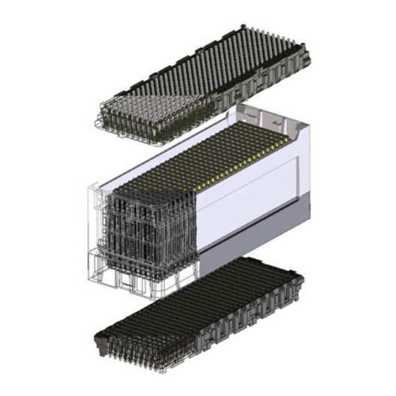
Page 66: System Level Assembly
Revision 3.10 Section 12 System Level Assembly The Hirose IT3/IT5 connector system’s separation height is set by interposers that are installed at the system level, after the circuit assembly process is complete. The interposers can be installed by hand, with common hand tools, or with customized fixtures. For high assembly volumes, dedicated tooling is suggested to ensure quality and ease of operation. - Page 67 IT3/IT5 Connector System YSTEM EVEL SSEMBLY Document Number: ETAD-F0458 Revision 3.10 The spacers a re ins talled (not shown) and the ma ting recepta cle is aligned wi th the interposer and pressed on as shown below: Mating Receptacle Polarity chamfer Interposer Polarity cha mfer Precaution: It is very important to provide good underside board support when i nstalling...
-
Page 68: Manual Assembly
IT3/IT5 Connector System YSTEM EVEL SSEMBLY Document Number: ETAD-F0458 Revision 3.10 * For more informa tion on PWB support and allowable deflections , reference IPC-JEDEC 9704, Printed Wiring Board Strain Gage Test Guideline. 12.2 Manual Assembly Position interposer di rectl y over mounting receptacle, ali gning the polari ty chamfers . When positioned properl y, the interposer should slide easil y onto the mounting recepta cle. -
Page 69: Installation Cap
IT3/IT5 Connector System YSTEM EVEL SSEMBLY Document Number: ETAD-F0458 Revision 3.10 The spa cers help align the mati ng receptacle with the interposer. If positioned correctl y, the ma ting recepta cle will slip down into the interposer. Push directly down on the assembl y to lock the ma ting recepta cle in place. -
Page 70: Assembly Fixturing
IT3/IT5 Connector System YSTEM EVEL SSEMBLY Document Number: ETAD-F0458 Revision 3.10 12.4 Assembly Fixturing For most consistent resul ts , and to i mprove ease of opera tion, a simple fixturing system is suggested: Board-to-Board Assembly Fixturing Insert spacer nuts into nests in assembly fixture. Place motherboard on fixture. - Page 71 IT3/IT5 Connector System YSTEM EVEL SSEMBLY Document Number: ETAD-F0458 Revision 3.10 Insert a reusable plastic interposer installation cap into each interposer. Caps should be clean, free of oil, dust or debris. If cap is dirty or worn, replace with new cap. Use top press plate to push directly down on interposers and lock them into place.
- Page 72 IT3/IT5 Connector System YSTEM EVEL SSEMBLY Document Number: ETAD-F0458 Revision 3.10 Install spacers. Tighten to specified torque. Remove protective interposer installation caps. Save caps for reuse. Leave caps on during spacer installation process to protect wafers from dropped fasteners or tools. Precaution: It is very i mportant to tighten nuts to torque speci fied by OEM.
- Page 73 IT3/IT5 Connector System YSTEM EVEL SSEMBLY Document Number: ETAD-F0458 Revision 3.10 Use press plate to lock mating receptacles into interposers. Press force should not exceed 500N for 300 pos, 400N for 200 pos, and 300N for 100 pos. Example: One 200-signal connector: do not exceed 400N insertion force Two 200-signal connectors (400 signals): do not exceed 800N insertion force.
-
Page 74: System Level Disassembly
Revision 3.10 Section 13 System Level Disassembly The Hirose IT3/IT5 three-piece connector system can be disassembled if a mother board or daughter card requires replacement. Both the mating receptacle and the interposer are removable. When removing a card or a connector component, the circuit boards should be handled with great care to prevent damage to them. -
Page 75: Interposer Assembl Y Removal
IT3/IT5 Connector System YSTEM ISASSEMBLY Document Number: ETAD-F0458 Revision 3.10 The daughter ca rd should be lifted straight up off the interposers . To minimize unnecessary flexing of the daughter ca rd, the removal forces should be applied as close to the interposer as possible wi thout contacting any components. On densel y popula ted assemblies, the edges ma y be the onl y open a rea tha t can be grasped. - Page 76 IT3/IT5 Connector System YSTEM ISASSEMBLY Document Number: ETAD-F0458 Revision 3.10 For removal , interposer shoul d be grasped by these sides as shown. They do not ha ve locking la tches . Grasp by sides Locking Latch Interposer Removal by Hand 1) Hold the Interposer Assembly 2) Gently rotate one side of the Interposer on the walls without IT3 locking...
- Page 77 IT3/IT5 Connector System YSTEM ISASSEMBLY Document Number: ETAD-F0458 Revision 3.10 An interposer removal tool is also a vailable. This tool is not an interposer installation cap, so please do not use it to install an interposer. Doi ng so ma y da mage an interposer. Interposer Removal with Tool 1) Cover the Interposer Assembly 2) Gently rotate one side of the...
- Page 78 HIROSE ELECTRIC (U.S.A.), INC. High Speed Interconnects 3255 Scott Blvd., Building 7, Ste. 101, Santa Clara, CA 95054, U.S.A. www.hiroseusa.com...
Need help?
Do you have a question about the Hirose IT3 and is the answer not in the manual?
Questions and answers