Advertisement
Quick Links
1. Scope
This document specifies the steps to insert or remove the DF63 series.
It contains general guidelines and precautions for the safe use of the product. The use of the
product in a way not as specified in the document could result in unexpected troubles such as
damage to connectors. Please make sure to thoroughly read and understand the document
prior to the use of the product.
2. Connectors
Part No.
DF63%-*S-3.96C(##)
DF63%-*P-3.96DS(A)(##)
DF63%-*EP-3.96C(##)
DF63%-****SC(F)(A)
DF63%-****PC(F)(A)
(E.g.)DF63-3S-3.96C
+DF63-1618SCF(Cables attached)
COUNT
DESCRIPTION OF REVISIONS
△
0
名 称
TITLE
DF63 Series Mating / Unmating Operation Instruction Manual
TECHNICAL SPECIFICATION
FORM HC0011-9-1
Description
Socket
Header
In-line Plug
Crimp contact
(E.g.)DF63M-3P-3.96DSA
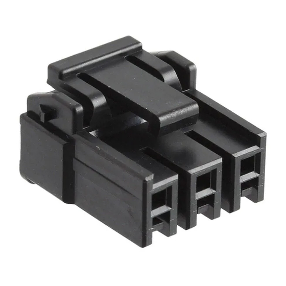
Fig1.DF63 connector
DESIGNED
DF63M-3P-3.96DS
DF63-3EP-3.96C
DF63A-3EP-3.96C
CHECKED
HIROSE ELECTRIC CO.,LTD.
APPROVED
HS.OKAWA
CHECKED
SZ.ONO
DESIGNED
TO.KUROMATSU
WRITTEN
TO.KUROMATSU
ETAD-H0892-00
DATE
20190514
20190514
20190514
20190514
△
1 / 6
0
Advertisement

Related Manuals for HRS DF63 Series


Summary of Contents for HRS DF63 Series
- Page 1 1. Scope This document specifies the steps to insert or remove the DF63 series. It contains general guidelines and precautions for the safe use of the product. The use of the product in a way not as specified in the document could result in unexpected troubles such as damage to connectors.
- Page 2 3. Operation procedure 3-1. Insertion 3-1-a. Positioning for insertion: :Adjust the position for insertion according to the locks of the socket or In-line plug. Center position Fig2. Positioning for insertion 3-1-b. Insertion: Insert the socket till it clicks while retaining the adjusted position. Then, it is not needed to handle the lock portion (If it is inserted the socket by pushing the lock portion, it does not hear click sound.) Lock...
- Page 3 To avoid degraded quality, do not tilt the socket for insertion as shown in the figure below. Fig.4 Prohibited insertion 3-1-c. Check fitting: Make sure the socket has been firmly fit with the header or In-line plug. (Check that the socket lock has been caught at the header lock or In-line plug lock by slightly pulling a cable by hand.) To remove the socket, refer to 3-2.
- Page 4 3-2. Socket removal 3-2-a. Removal: :Remove the socket while pressing with a finger the lock spring on the socket to unlock. Lock spring Direction of removal Fig.5 Socket removal To avoid degraded quality, do not tilt the socket for removal as shown in the figure below.
- Page 5 Attention)Not to remove socket in the locked status as it will lead to breakage of locking portion or cable broken. If remove socket in the locked status, the lock is engaged to header lock portion as below picture shown. Then, it can not handle the lock. In this case, please insert the socket once.
- Page 6 4. Precautions ・Do not insert or remove the socket while electrifying. ・Excessive external force applied to connectors could cause fault or damage. Therefore, avoid forced insertion or removal, impacts given by falling, or forced pulling of cables. ・Avoid insert socket by bundling the cable or applying stress to the socket like below picture shown.
Need help?
Do you have a question about the DF63 Series and is the answer not in the manual?
Questions and answers