Advertisement
July 2021
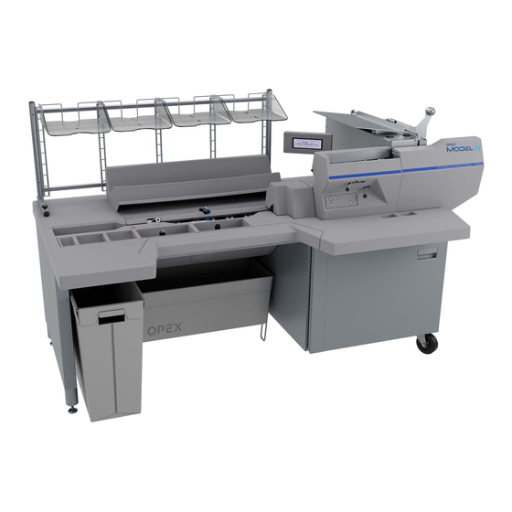
Model 72™ Operator Manual
Manual #5068800
Revision 21-01
Original Instructions
Model 72™
®
© 2012, 2015, 2021 OPEX
Corporation
All rights reserved. This document is provided by OPEX for use by their customers, partners and dealers. No portion
of these materials may be reproduced, published, or stored in a database or retrieval system, other than for its
intended use without the express, written consent of OPEX Corporation.
Advertisement

Related Manuals for Opex Model 72


Summary of Contents for Opex Model 72
- Page 1 © 2012, 2015, 2021 OPEX Corporation All rights reserved. This document is provided by OPEX for use by their customers, partners and dealers. No portion of these materials may be reproduced, published, or stored in a database or retrieval system, other than for its...
-
Page 2: Contacting Opex
Fax: +1 856.727.1955 https://www.opex.com/ If you find errors, inaccuracies, or any other issues or concerns with this document, please contact the OPEX Technical Writers via email at: GroupDMATechwriters@opex.com For help with opexservice.com website-related issues, please contact the OPEX Web Developers via email at: GroupWebDev@opex.com... -
Page 3: Ec Declaration Of Conformity
Bolton BL1 4AY United Kingdom Type of Equipment: Automatic Mail Opener Model No. : RAPID EXTRACTION DESK - MODEL 72 Serial No. : Year of Manufacture: I, the undersigned, hereby declare that the equipment specified above conforms to the above Directive(s) and Standard(s). -
Page 4: Declaration Of Conformity - Fr
Les Ulis, France Type of Equipment: Automatic Mail Opener Model No. : RAPID EXTRACTION DESK - MODEL 72 Serial No. : Year of Manufacture: I, the undersigned, hereby declare that the equipment specified above conforms to the above Directive(s) and Standard(s). -
Page 5: Declaration Of Conformity - De
Walldorf, Germany Type of Equipment: Automatic Mail Opener Model No. : RAPID EXTRACTION DESK - MODEL 72 Serial No. : Year of Manufacture: I, the undersigned, hereby declare that the equipment specified above conforms to the above Directive(s) and Standard(s). -
Page 6: Document History
- added new OPEX logo 21-01 July 26, 2021 Page 3 - added Declaration of Conformity section Page 28 - overall improvements in “Model 72 components & features” Page 33 - added “Model/Serial number location” section (continued on next page) Model 72™... - Page 7 - improved graphic reference description Page 80 - improved description for “Display Graph” Page 89 - updated Feeder Cover photo Page 94 - Sensors section added Page 103 - added “About OPEX Corporation” & back cover. Model 72™ Operator Manual OPEX Corporation...
-
Page 8: Table Of Contents
2.3. Model 72 Safety Labels ................ 20 2.4. Ergonomics ................... 26 Chapter 3 Overview 3.1. Model 72 Components and Features ............ 28 3.2. Power Panel ..................31 3.2.1. Software options ................32 3.3. Model/Serial Number Location .............. 33 3.4. Specifications ..................34 3.4.1. - Page 9 5.4. Job Parameters ..................67 5.4.1. JOB NAME ..................68 5.4.2. ACTIVATION MODE ..............68 5.4.3. EXTRACT POSITION ..............70 5.4.4. MAIL HEIGHT OPTION ..............71 5.4.5. VERIFIER OPTION ............... 72 Table of Contents Model 72™ Operator Manual OPEX Corporation...
- Page 10 6.4. Emptying the Cutter Trash ..............88 6.5. Changing the Feeder belts ..............89 6.6. Changing the retard tire ................ 91 Chapter 7 Troubleshooting 7.1. Sensors ....................94 7.2. Error messages ..................95 Table of Contents Model 72™ Operator Manual OPEX Corporation...
-
Page 11: Introduction
1.1.1. Manual navigation aids ....... . 12 1.1.2. Model 72 documentation ....... 12 1.2. -
Page 12: About The Manual
• minor maintenance and cleaning This information is intended for use by Model 72 operators. The operator can power up the Model 72, start a job, and extract contents from envelopes. They can also perform minor maintenance. This manual will be updated to reflect Model 72 design changes, or to correct... -
Page 13: Safety Message Conventions
This manual uses the following conventions to alert you about safety hazards associated with certain procedures and situations. Please be aware of these conventions when reading the manual and operating the Model 72: DANGER Indicates a hazardous situation that, if not avoided, will result in death or severe injury. - Page 14 (This page is intentionally blank) Introduction Model 72™ Operator Manual OPEX Corporation...
-
Page 15: Safety
2.2.1. Maintenance Safety ........19 2.3. Model 72 Safety Labels ....... . . 20 2.4. -
Page 16: Introduction
2.1. Introduction The information provided in this chapter is intended to educate you on various safety issues regarding the operation and maintenance of the OPEX Model 72 described in this manual. This chapter provides an explanation of the safety guidelines to be observed when working with the Model 72, identification and location of safety labeling used on the Model 72, and ergonomic considerations. -
Page 17: Safety Guidelines
Model 72 described in this manual. - Operator training is required prior to operating the Operator training Model 72. Please read through this manual prior to operating the Model 72. Optional Lift system - If your desk has the optional lift system (Figure 2-1), care must be taken to not create a pinch point between the desk and your body. - Page 18 - The cutter blades are sharp and may cause cuts should you inadvertently come in contact with them whether the Model 72 is running or not. Do not place fingers in the feed area while running the Model 72. - Do not operate the Model 72 with the cover doors removed.
-
Page 19: Maintenance Safety
2.2.1. Maintenance Safety WARNING Unplug the Model 72 from the power source to remove power from the Model 72 for servicing or when moving the Model 72. Only authorized personnel are permitted to service and maintain the Model 72. Stop the Model 72 before attempting to open or remove exterior panels. -
Page 20: Model 72 Safety Labels
2.3. Model 72 Safety Labels Safety labels are used in specific locations on the Model 72 to alert you to certain safety hazards. These labels may appear in various languages or styles depending on the region or country where the Model 72 is operating: •... - Page 21 2.3.0.1. Ratings / Serial Number label Location: Inside cabinet door (Table 2-1). Purpose: Identifies product electrical ratings, Model 72 serial number. Table 2-1: Ratings/Serial Number label Label locations Description 7459201 (EU) 7822000 (JP 50HZ) 7459200 (US) 7822100 (JP 60Hz) Note that the Ratings/Serial Number labels in the right column show the WEEE symbol.
- Page 22 (2) this device must accept any interference received, including interference that may cause undesired operation. ® Contains FCC ID: VDM2054710 Contains IC: 7175A-2054710 Model: 205471010 OPEX Corporation Japan only: MIC registration (7682640) Safety Model 72™ Operator Manual...
- Page 23 2.3.0.3. Pinch Point Caution Label Location: The beginning of the feed path (Table 2-3). Purpose: Warns about pinch hazards within the feed path. Table 2-3: Pinch Point Caution label Label locations Description ALL (1637200) Safety Model 72™ Operator Manual OPEX Corporation...
- Page 24 Location: Inside the cabinet door (Table 2-4). Purpose: To inform personnel that the ground points in the Model 72 are well connected between each other and it has passed the ground bond test. Table 2-4: Dielectric and ground test label...
- Page 25 2.3.0.5. Ground Symbol Location: On the inside of the frame near the power panel (Table 2-5). Purpose: Identifies Ground cable connection point. Table 2-5: Ground Symbol label Label locations Description All (P24835-01) Safety Model 72™ Operator Manual OPEX Corporation...
-
Page 26: Ergonomics
• Maintain an upright body posture. • Occasionally change the angle of your posture for greater comfort. • Avoid operating the Model 72 for longer than a single 8-hour shift. If possible, stretch between breaks. • If your Model 72 is equipped with the optional height adjustment, adjust the height of the desk so that you are able to work comfortably in a position which maintains good posture. -
Page 27: Overview
3. Overview 3.1. Model 72 Components and Features ..... . 28 3.2. Power Panel......... . . 31 3.2.1. -
Page 28: Model 72 Components And Features
Before using the Model 72, take time to familiarize yourself with its main components and features (see Figure 3-1 and Table 3-1). - Page 29 Table 3-1: Model 72 Components & Features Integral mail rack & conveyor • Holds mail tray. Pushes in to fit flush below conveyor when not in use. • Conveyor can hold up to 22½ inches (571.5 mm) of mail. Sort bins and sort tray •...
- Page 30 Table 3-1: Model 72 Components & Features (continued) Shuttle (bird’s eye view from front) The shuttle moves up and down to position the envelope for the top cut. Extractor • Where envelope contents are removed • The envelope opening width is adjustable...
-
Page 31: Power Panel
3.2. Power Panel The power panel is located at the back of the Model 72 and contains the following controls and connectors: Power Panel Component/Function Main Power On/Off Switch Allows building-supplied AC to enter the Model 72. The switch should be off whenever maintenance is performed. -
Page 32: Software Options
Printer - enables printer functionality. - The Model 72 may be attached to a network and integrated using OPEX Network Solution (ONS) software. This allows machine parameters, job parameters, and operator information to be read from or written to the Model 72 by a central computer. -
Page 33: Model/Serial Number Location
3.3. Model/Serial Number Location Before contacting OPEX Technical Support, locate the Model/Serial label on your Model 72 so that you can provide the assisting technician with your Reference Serial Number (Figure 3-2). See contact information on page Figure 3-2: Model/Serial label Overview Model 72™... -
Page 34: Specifications
Weight (base model) <500 lbs. (<226.796 kg) Lift Height Adjustment 25 to 32.5 inches (635 mm to 825.5 mm) Operator/Service Three feet, front and right sides (914.4 mm) Clearance Sound Output below 80dB Overview Model 72™ Operator Manual OPEX Corporation... -
Page 35: Electrical Specifications
NA: 1110W (Max @ 9.25A) Power Rating EU: 990 - 1080W (Max @ 4.5A) JP: 750W NA: 3788BTU/h (Max @ 9.25A) BTU Rating EU: 3378 - 3685BTU/h (Max @ 4.5A) JP: 2561 BTU/hour Overview Model 72™ Operator Manual OPEX Corporation... - Page 36 (This page is intentionally blank) Overview Model 72™ Operator Manual OPEX Corporation...
- Page 37 4.10. Stopping a job ........53 Model 72™...
-
Page 38: Operation
4.1. Keypad button functionality The Model 72 controls are located on the keypad to the right of the operator as indicated in Figure 4-1. Up Arrow Cancel Left Arrow Right Arrow Down Arrow Enter Start Stop Figure 4-1: Model 72 keypad button names The Keypad is used to select options and move from menu to menu on the LCD Display. - Page 39 Right Arrow Hold - will continuously shift the selection one item to the right until the key is released. It will work the same as the right arrow press. Operation Model 72™ Operator Manual OPEX Corporation...
-
Page 40: Enhanced Scrolling
Figure 4-2: Typical enhanced scrolling screen 4.3. Powering up 1. Turn the main power switch (located on the back of the Model 72) on. 2. Press the Start button on the keypad. The welcome screen will appear first, prior to the Logon screen (Figure 4-3). -
Page 41: Logging In
Figure 4-4: Login screen 2. Press the Enter button on the keypad to display the SELECT OPERATOR screen. OPEX provides two default operators: NEW and SUPERVISOR. When new operators are added by a Supervisor, the names will be displayed along with the OPEX defaults (Figure 4-5). - Page 42 SAV and press Enter on the keypad. Operator login is valid until the Stop button is pressed (LCD off). If you entered an incorrect password, the INCORRECT PASSWORD warning message is displayed (Figure 4-8). Figure 4-8: Incorrect Password screen Operation Model 72™ Operator Manual OPEX Corporation...
-
Page 43: Changing Operator Passwords
(Figure 4-9). Figure 4-9: Main Menu The CHECK PASSWORD screen (Figure 4-10) will be displayed to remind the operator that leaving the password blank will disable the password feature. Figure 4-10: Check Password screen Operation Model 72™ Operator Manual OPEX Corporation... - Page 44 4. Enter the new password using the keypad. The password can be up to 10 characters in length. Selecting SAV will save the new password. The LCD will return to the main menu after entering a password. Operation Model 72™ Operator Manual OPEX Corporation...
-
Page 45: Selecting A Job
Enter button. The Select Job screen appears (Figure 4-13). Figure 4-13: Select Job screen Note: If there are a large number of jobs stored in the Model 72. there may be additional steps, as explained in “Locating a job when many are stored” on page 5. -
Page 46: Operator Statistics
Operators are able to view their own statistics only, and can also print their own statistics if the Model 72 has an optional printer. If printing is enabled, two additional options, PRINT DETAILS and PRINT SUMMARY, will be displayed on the DISPLAY STATISTICS screen. - Page 47 (Figure 4-18) and press Enter. Figure 4-18: Display Statistics screen Based on the selection made, the information is either displayed or printed. Figure 4-19 shows an example of the VIEW DETAILS selection. Figure 4-19: Statistics detail example Operation Model 72™ Operator Manual OPEX Corporation...
-
Page 48: Loading Envelopes
Procedure to load envelopes: 1. Align the envelopes so that they are all oriented with the label side facing towards the front of the Model 72, and the back flap on top and facing towards the back of the Model 72 (Figure 4-21). - Page 49 6. Lift the Pusher, slide it back, and place it behind the last envelope. You will find that it is easier to load in this manner than to try to load all of the mail in front of the Pusher. Operation Model 72™ Operator Manual OPEX Corporation...
-
Page 50: Setting Cutter Positions
4.8. Setting cutter positions The side and top cutter on the Model 72 are operator-adjustable (Figure 4-22). TOP CUTTER No Cut Deep Cut SIDE CUTTER Deep Cut No Cut Figure 4-22: Cutter levers The top cutter has five positions: • POSITION 0 - No Cut (knob fully left) •... -
Page 51: Running A Job
1. After the job is selected, press the Enter button on the keypad. The green lens is illuminated when the Model 72 has been turned on. The LCD will display the Run screen (Figure 4-23), and envelope feeding will begin. - Page 52 With the Verifier enabled, and contents are detected, the red light will flash, and the Model 72 will not advance the envelope into the trash. 3. Press the green Cycle button to send the empty envelope to the verifier.
-
Page 53: Stopping A Job
A job may be ended at any time by pressing the Cancel button. With the job run memory mode enabled, the Model 72 will save two consecutive runs of the same job by the same operator as a single run. The two runs must occur within a predetermined timeout period (set by your service technician or system administrator). - Page 54 (This page is intentionally blank) Operation Model 72™ Operator Manual OPEX Corporation...
-
Page 55: Managing Operators And Jobs
5.6.1. Display Data ........78 Model 72™... - Page 56 5.6.6. Print Data......... . . 81 Managing Operators and Jobs Model 72™ Operator Manual OPEX Corporation...
-
Page 57: Managing Operators
- CHANGE JOB LIST - adding, modify and printing of jobs - STATISTICS MENU - viewing and printing of statistical reports - PASSWORD OPTION - globally enable or disable all passwords Managing Operators and Jobs Model 72™ Operator Manual OPEX Corporation... -
Page 58: Change Operator List
• SORT LIST - alphabetically sort the operator list. • PRINT - select an operator from the operator list and print all parameters associated with the selected operator. • PRINT ALL - print the entire list of operators. Managing Operators and Jobs Model 72™ Operator Manual OPEX Corporation... -
Page 59: Add Operator
The new operator will be placed after the selected operator, and the MODIFY OPERATOR screen appears (Figure 5-5). Figure 5-5: Modify Operator screen 4. Make any modification to the operator’s parameters using the keypad buttons. Operator parameters include: Managing Operators and Jobs Model 72™ Operator Manual OPEX Corporation... -
Page 60: Delete Operator
The operator will be deleted, and the display will return to the CHANGE OPERATOR LIST screen. 5.2.3. Change Operator 1. On the CHANGE OPERATOR LIST screen, select CHANGE. The SELECT OPERATOR screen will appear (Figure 5-7). Figure 5-7: Select Operator screen Managing Operators and Jobs Model 72™ Operator Manual OPEX Corporation... -
Page 61: Select Operator
The selected operator will become the current operator. 5.2.5. Sort List 1. On the CHANGE OPERATOR LIST screen, select SORT LIST. 2. Selecting SORT LIST will alphabetically sort the operator list. Managing Operators and Jobs Model 72™ Operator Manual OPEX Corporation... -
Page 62: Print All Or Individual Operator Parameters
You must be logged in as supervisor to print out the report. Note: If you want to print information for a specific operator, you will be presented with an additional screen where you can choose the operator. Managing Operators and Jobs Model 72™ Operator Manual OPEX Corporation... -
Page 63: Creating Jobs
• SORT LIST - alphabetically sort the job list. • PRINT - select a job from the job list and print all parameters associated with the selected job. • PRINT ALL - print the entire list of jobs. Managing Operators and Jobs Model 72™ Operator Manual OPEX Corporation... -
Page 64: Adding A New Job
3. Place the cursor over an existing job and press Enter to place the job in the list. The new job will be placed after the selected job, and the SELECT JOB OPTION screen appears (Figure 5-15). Figure 5-15: Select Job Option screen Managing Operators and Jobs Model 72™ Operator Manual OPEX Corporation... -
Page 65: Locating A Job When Many Are Stored
LCD, it can be difficult to find and select a specific job. If you have a large amount of jobs stored in the Model 72, there are two screens that can be used to help locate a specific job quickly (see Figure 5-16): The SELECT JOB PAGE screen (left) can display multiple pages of jobs in alpha-numerical order. - Page 66 - If the number of jobs is less than the machine parameter setting, or the SELECT JOB PAGE screen is disabled, the LCD will display the SELECT JOB screen (Figure 5-20). Scrollbar denotes position in list Figure 5-20: Select Job screen Managing Operators and Jobs Model 72™ Operator Manual OPEX Corporation...
-
Page 67: Job Parameters
(Figure 5-22). Figure 5-22: Select Job Option screen 4. Use the Up/Down arrows to highlight a job parameter, and press Enter to select it. The available job parameters are described below. Managing Operators and Jobs Model 72™ Operator Manual OPEX Corporation... -
Page 68: Job Name
This mode is the preferred choice when most of the envelopes in a job exhibit a consistent thickness. When selecting content activation, make sure that any slight Managing Operators and Jobs Model 72™ Operator Manual OPEX Corporation... - Page 69 • Removal mode - When removal activation is enabled, the removal sensor located in front of the extraction area is used to signal that an envelope is empty. Typically, the operator removes all the contents and in the same Managing Operators and Jobs Model 72™ Operator Manual OPEX Corporation...
-
Page 70: Extract Position
For example, if this parameter is set to 4, the leading edge of the envelope should stop four inches past the middle of the extraction cups. Managing Operators and Jobs Model 72™ Operator Manual OPEX Corporation... -
Page 71: Mail Height Option
Use the right or left arrows to select FIXED HEIGHT, VARYING HEIGHT or HYBRID and press Enter to save the change. It is important to note that the Model 72 will run in any mode with any type of envelope. However, setting this parameter can greatly improve performance. -
Page 72: Verifier Option
This parameter can be used to “fine tune” how the verifier is sensing empty envelopes. Use the on-screen instructions to set the verifier to its optimal setting (Figure 5-30). Figure 5-30: Verifier voltage change screen Managing Operators and Jobs Model 72™ Operator Manual OPEX Corporation... -
Page 73: Graph Reference
The Transport Height scale from 1-10 corresponds to 0.2875” (7.3025 mm) increments from 3.5” (88.9 mm) to 6.375” (161.925 mm). • Mathematically in inches: (6.375-3.5)/10= 0.2875 • Mathematically in millimeters: (161.925-88.9)/10= 7.3025 Managing Operators and Jobs Model 72™ Operator Manual OPEX Corporation... -
Page 74: Cup Open Amount
The recommended cut amount can be adjusted by moving the cursor with the right and left arrows and pressing Enter. Managing Operators and Jobs Model 72™ Operator Manual OPEX Corporation... -
Page 75: Print All Jobs Or Individual Job Parameters
Figure 5-36: Change Job List screen Note: If you want to print information for a specific job, you will be presented with an additional screen where you can choose the job. Managing Operators and Jobs Model 72™ Operator Manual OPEX Corporation... -
Page 76: Password Options
2. Use the left/right arrows to select OPERATOR PASSWORDS and press Enter. The OPERATOR PASSWORDS screen appears (Figure 5-38). Figure 5-38: Operator Passwords screen 3. Use the arrows to select DO NOT ALLOW OPERATOR PASSWORDS, and press Enter. Managing Operators and Jobs Model 72™ Operator Manual OPEX Corporation... -
Page 77: Supervisor Statistics
2. Use the arrow buttons to highlight STATISTICS MENU, and press Enter. The STATISTICS menu appears (Figure 5-40). Figure 5-40: Statistics menu (Supervisor) The Supervisor STATISTICS menu offers the supervisor the ability to view and edit additional information. Managing Operators and Jobs Model 72™ Operator Manual OPEX Corporation... -
Page 78: Display Data
You can use the Graph Reference screen to change the appearance of the graph displayed while the Model 72 is running. This selection is used to set the target rate expected of the operator(s). The reference appears as a horizontal line running through the graph on the run screen. -
Page 79: Update Clock
Note: For more on this parameter, see page 5.6.3. Update Clock This is used to update the Model 72 clock. 1. In the supervisor STATISTICS Menu, select UPDATE CLOCK and press Enter. The UPDATE CLOCK screen appears (Figure 5-43). Figure 5-43: Update Clock screen 2. -
Page 80: Display Graph
Graph data is stored for the last two days the Model 72 was run. These dates are displayed on the left side of the two time lines. For example, the current... -
Page 81: Reset Data
• OPERATOR REPORT - prints an Operator Statistics Report. • PAPER FEED - advances paper through the printer. • SET TIME RANGE - select a time range for your printed report. Managing Operators and Jobs Model 72™ Operator Manual OPEX Corporation... - Page 82 (This page is intentionally blank) Managing Operators and Jobs Model 72™ Operator Manual OPEX Corporation...
-
Page 83: Maintenance
6.6. Changing the retard tire ....... . . 91 Model 72™... -
Page 84: Adjust Lcd Contrast
The value can range from 0 (lightest) to 255 (darkest). 4. Once the contrast level is set for operator preference, press Cancel to exit the “adjust intensity” screen. Maintenance Model 72™ Operator Manual OPEX Corporation... -
Page 85: Adjusting The Desk Height (If Enabled)
To raise or lower the desk This feature is only available on a Model 72 with the option lift system installed and enabled. 1. When the LIFT SYSTEM machine parameter is enabled, the arrows on the Login, Run and Pre-Run screens alert you that it is possible to raise or lower the desktop work surface (see Figure 6-2). - Page 86 Figure 6-3: Lift system in motion (moving up) The table will continue to move until the Up/Down button is released, the table has reached the travel limit, or travel time has surpassed a non- adjustable time limit (timed out). Maintenance Model 72™ Operator Manual OPEX Corporation...
-
Page 87: Routine Maintenance
It is important that you keep your Model 72 clean and in good working order. This will prolong the overall life of the Model 72 and result in longer periods of “up” time. Failure to perform daily cleaning tasks may result in the voiding of your service contract. -
Page 88: Emptying The Cutter Trash
6.4. Emptying the Cutter Trash If the optional slicing cutter is installed, as the Model 72 is run, top cutter chips will accumulate in the trash bin directly in front of the operator’s feet. If the milling cutter is installed, the trash bin in front of the operator’s feet is not required. -
Page 89: Changing The Feeder Belts
The feeder belts are operator changeable. If the belts look worn, cracked, or have become brittle, they will need to be replaced. 1. Carefully remove the cover from the feeder area by lifting it up and away from the Model 72 (Figure 6-5). Feeder cover Figure 6-5: Front cover 2. - Page 90 6. Replace the front cover making sure to align the holes in the cover with the three screws (see Figure 6-7) for proper placement. Align cover to these three screws Figure 6-7: Reinstall the feeder cover Maintenance Model 72™ Operator Manual OPEX Corporation...
-
Page 91: Changing The Retard Tire
4. Pull the rubber tire off the roller. 5. Examine, and replace the tire (#7226500) if needed. 6. Lower the hinged cover. 7. Reattach the feeder cover (as explained in “Changing the Feeder belts” on page 89). Maintenance Model 72™ Operator Manual OPEX Corporation... - Page 92 (This page is intentionally blank) Maintenance Model 72™ Operator Manual OPEX Corporation...
-
Page 93: Troubleshooting
7.2. Error messages........95 Model 72™... -
Page 94: Sensors
7.1. Sensors The Model 72 uses sensors for a variety of purposes such as: track the envelope as it moves through the Model 72, measure the height and width of the envelope, detect contents in the envelope, verify if the contents have been removed from the envelope, and set the minimum and maximum height settings for the lift system (Figure 7-1). -
Page 95: Error Messages
7.2. Error messages When a Model 72 stops for a reason other than the operator canceling out of a job, the LCD will display an error message. Each error message is numbered. Note the number and find the message in the table below. - Page 96 PLEASE CLEAR THE EXTRACT ENTRY If the trail edge of the envelope is not seen within a defined amount of time, then the envelope must be hung up, so this jam is called. Clear any envelopes. Troubleshooting Model 72™ Operator Manual OPEX Corporation...
- Page 97 After the verifier section is stopped and an envelope is not detected at the Discard sensor, the transport is stopped and this jam is called. Check and resume operation. Troubleshooting Model 72™ Operator Manual OPEX Corporation...
- Page 98 It can also be caused by the fence stuck in the down position, allowing the fed envelope to slide immediately down into the shuttle. Clear any envelopes in the feed tray. Troubleshooting Model 72™ Operator Manual OPEX Corporation...
- Page 99 Empty the trash. INTERLOCK-1 IS OPEN This jam is called if the hinged cover located just above the feeder retard wheel is opened before or during a Model 72 run. Close the cover. Troubleshooting Model 72™ Operator Manual...
- Page 100 Error Message & Description INTERLOCK-2 IS OPEN This jam is called if the feeder cover located to the right of the feed tray is removed or opened before or during a Model 72 run. Close the cover. INTERLOCK-3 IS OPEN This jam is called if the top cutter cover is opened before or during a Model 72 run.
- Page 101 Place a service call. PLEASE CLEAR THE SIDE CUTTER NIP This jam is called when the Side Cut Justifier sensor is blocked during the start of Model 72 run. Clear the feed tray area. PLEASE CLEAR UPPER JUSTIFIER SENSOR This jam is called when the Upper Justifier sensor is blocked during the start of Model 72 run.
- Page 102 Place a service call if the problem persists. COMM FAULT This jam is called when the controller side is having difficulties sending messages to the Smart Driver board. Place a service call if the problem persists. Troubleshooting Model 72™ Operator Manual OPEX Corporation...
- Page 103 About OPEX Corporation OPEX Corporation is more than a manufacturer of machines. We continuously reimagine technology to power the future for our customers. With an innovative approach, we engineer unique automated solutions that support our customers so they can solve the most pressing business challenges for both today and tomorrow.
- Page 104 OPEX Corporation | 305 Commerce Drive | Moorestown, NJ 08057-4234 | USA http://www.opex.com...
Need help?
Do you have a question about the Model 72 and is the answer not in the manual?
Questions and answers