Table of Contents
Advertisement
Available languages
Available languages
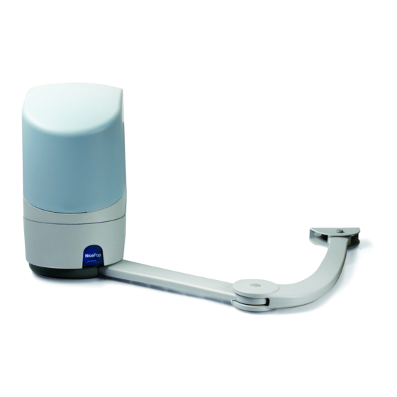
POP
PP7124
PP7224
Swing gate opener
EN -
Instructions and warnings for installation and use
IT -
Istruzioni ed avvertenze per l'installazione e l'uso
FR -
Instructions et avertissements pour l'installation et l'utilisation
ES -
Instrucciones y advertencias para la instalación y el uso
DE -
Installierungs-und Gebrauchsanleitungen und Hinweise
PL -
Instrukcje i ostrzeżenia do instalacji i użytkowania
NL -
Aanwijzingen en aanbevelingen voor installatie en gebruik
Advertisement
Chapters
Table of Contents

Related Manuals for Nice POP PP7124


Summary of Contents for Nice POP PP7124
- Page 1 PP7124 PP7224 Swing gate opener EN - Instructions and warnings for installation and use IT - Istruzioni ed avvertenze per l’installazione e l’uso FR - Instructions et avertissements pour l’installation et l’utilisation ES - Instrucciones y advertencias para la instalación y el uso DE - Installierungs-und Gebrauchsanleitungen und Hinweise PL -...
-
Page 3: Table Of Contents
Incorrect installation may cause serious injury. Before commencing work, all sections of the manual must be read carefully. If in any doubt, suspend installation and call the Nice Support Service for clarifi- cation. • IMPORTANT! – This manual contains important instructions. Keep it for future maintenance work and disposal of the product. -
Page 4: Installation
3.3 - Preliminary installation set-up work Fig. 3 provides an example of an automation system, produced using Nice com- INSTALLATION ponents (some components may not be present in the kit): a - Gearmotor with control unit model PP7124 b - Gearmotor without control unit model PP7224 3.1 - Pre-installation checks... -
Page 5: Manually Releasing And Locking The Gearmotor
Overlapping leaf PP7124 The electrical connection of the various devices (photocells, digital keyboard, transponder card readers, etc.) contained in the automation with the control unit must be made by means of the Nice “Bluebus” system. PP7224 PP7224 Overlapping leaf Overlapping leaf... -
Page 6: Connection Of Other Devices
4.3 - Connection of other devices To indicate when the self-learning procedure is required, LEDs L1 and L2 on the control unit (fig. 15) emit a number of slow flashes: If further devices present in the system need to be powered, for example a 01. -
Page 7: Testing And Commissioning
03 of the manual learning procedure (paragraph 4.7.2). For all the documentation mentioned, the Nice technical support service pro- Repeat this operation for all other positions to be modified. -
Page 8: Level 1 Programming (On-Off Functions)
STOP/SET: key for stopping a manoeuvre; if pressed for more than 5 seconds, PROGRAMMING THE CONTROL UNIT it enables entry to programming mode. CLOSE (u): – key for controlling gate closure; – selection key during programming. 6.1 - Level one programming (ON-OFF functions The control unit has 3 keys OPEN (), STOP (SET), CLOSE (u) that can be All level 1 functions are set by default to “OFF”... - Page 9 TABLE 7 - Second level functions Input LED Parameter Value Description (level) Pause time 5 seconds Sets the pause time, namely the time which lapses before automatic clo- 15 seconds sure. This will only take effect if closing 30 seconds is active.
-
Page 10: Special Functions
List of Manoeuvre 1 result (most recent) The type of fault that has occurred in faults the last 8 manoeuvres can be establi- Manoeuvre 2 result shed Manoeuvre 3 result See TABLE 12 – Fault log. Manoeuvre 4 result Manoeuvre 5 result Manoeuvre 6 result Manoeuvre 7 result Manoeuvre 8 result... - Page 11 se. Table 10 shows the cause and solution for each type of signal. WHAT TO DO IF… The LEDs on the control unit also emit signals. Table 11 shows the cause and (troubleshooting guide) solution for each type of signal. It is possible to verify faults that have occurred during the last 8 manoeuvres.
-
Page 12: Connecting The Oview Programmer
TABLE 12 - Fault log 01. Press and hold down the “Set” key for approx. 3 seconds; 02. Release the key when LED “L1” starts flashing; 03. Press keys “” or “u” to move from the flashing LED to L8 LED (“input LED”) for the “Fault log” parameter; 04. -
Page 13: Connecting The Solar Power System Solemyo
connector to the dedicated seat. The Oview can be connected to several Con- 8.5 - Connecting the external release system Kio trol units simultaneously (up to 5 without any particular precautions, and up to 60 (fig. 20) observing the dedicated warnings) and can stay connected to the control unit CAUTION! –... -
Page 14: Technical Specifications Of Product
TECHNICAL SPECIFICATIONS OF PRODUCT WARNINGS: • All technical specifications stated in this section refer to an ambient temperature of 20°C (± 5°C). • Nice S.p.a. reserves the right to apply modifi- cations to products at any time when deemed necessary, maintaining the same intended use and functionality. -
Page 15: Product Lifetime
GRAPH 3 PRODUCT LIFETIME 250000 The lifetime is the average economic duration of the product. The value of lifeti- me is strongly influenced by the intensity of the manoeuvres performed by the automation. i.e. the sum of all factors that contribute to product wear (see Table 200000 15). -
Page 16: Ce Declaration Of Conformity
Declaration in accordance with the Directives: 2004/108/CE (EMC); 2006/42/EC (MD) appendix II, part B Note - The contents of this declaration correspond to declarations in the official document deposited at the registered offices of Nice S.p.a. and in partic- ular to the last revision available before printing this manual. The text herein has been re-edited for editorial purposes. A copy of the original declaration can be requested from Nice S.p.a. - Page 17 3.6 - Sbloccare e bloccare manualmente il motoriduttore ....3 rivolgersi al Servizio Assistenza Nice. • Non eseguire modifiche su nessuna parte del prodotto. Operazioni non per- 4 - COLLEGAMENTI ELETTRICI .
-
Page 18: Installazione
3.3 - Lavori di predisposizione all’installazione La fig. 3 mostra un esempio di impianto di automatizzazione, realizzato con INSTALLAZIONE componenti Nice (alcuni componenti possono non essere presenti nel kit): a - Motoriduttore con centrale mod. PP7124 b - Motoriduttore senza centrale mod. PP7124 3.1 - Verifiche preliminari all’installazione... -
Page 19: Sbloccare E Bloccare Manualmente Il Motoriduttore
Il collegamento elettrico dei vari dispositivi (fotocellule, tastiere digitali, lettori di tessere a transponder, ecc.) presenti nell’automazione, con la centrale di co - mando, deve essere effettuato tramite il sistema “Bluebus” di Nice. Descrizione dei collegamenti elettrici (fig. 11) PP7224... -
Page 20: Collegamento Di Altri Dispositivi
4.3 - Collegamento di altri dispositivi volta che uno di questi viene aggiunto oppure viene rimosso. I Led “L1” e “L2” presenti sulla centrale (fig. 15), emettono dei lampeggi lenti Se si necessita di alimentare ulteriori dispositivi previsti nell’impianto, ad esem- per indicare che è... -
Page 21: Verifica Del Movimento Delle Ante Del Cancello
4.8 - Verifica del movimento delle ante del cancello prietario sui pericoli ed i rischi residui ancora presenti. Per tutta la documentazione citata, Nice attraverso il proprio servizio di assi- Al termine della fase di apprendimento, si consiglia di far eseguire alla centrale stenza tecnica, mette a disposizione: manuali d’istruzioni, guide e moduli... -
Page 22: Programmazione Della Centrale Di Comando
STOP/SET: tasto per fermare una manovra; se premuto per più di 5 secondi PROGRAMMAZIONE DELLA CENTRALE permette di entrare in fase di programmazione. DI COMANDO CLOSE (u): – tasto per comandare la Chiusura del cancello; – tasto di selezio- ne in fase di programmazione. 6.1 - Programmazione primo livello (ON-OFF) Sulla centrale sono presenti 3 tasti OPEN (), STOP (SET), CLOSE (u) che possono essere utilizzati sia per comandare la centrale durante le fasi di prova... - Page 23 TABELLA 7 - Funzioni di secondo livello Led di Parametro Valore Descrizione entrata (livello) Tempo 5 secondi Regola il tempo di pausa, cioè il tem - Pausa po prima della richiusura automatica. 15 secondi Ha effetto solo se la Chiusura è attiva. 30 secondi 45 secondi 60 secondi...
-
Page 24: Funzioni Speciali
Elenco Esito 1 manovra (la più recente) Permette di verificare il tipo di anoma- anomalie lia avvenuta durante l’esecuzione delle Esito 2 manovra ultime 8 manovre. Esito 3 manovra Vedere TABELLA 12 - Elenco storico Esito 4 manovra delle anomalie Esito 5 manovra Esito 6... -
Page 25: Cosa Fare Se
peggi più brevi; questi vengono ripetuti due volte divisi da una pausa di 1 COSA FARE SE... secondo. Nella Tabella 10 sono descritte la causa e la soluzione per ogni tipo (guida alla risoluzione dei problemi) di segnalazione. Anche i Led presenti sulla centrale emettono delle segnalazioni; nella Tabella 11 sono descritte la causa e la soluzione per ogni tipo di segnalazione. -
Page 26: Approfondimenti
TABELLA 12 - Elenco storico delle anomalie 01. Premere e tenere premuto il tasto “Set” per circa 3 secondi; 02. Rilasciare il tasto quando il led “L1” inizia a lampeggiare; 03. Premere il tasto “” o “u” per spostarsi dal led che sta lampeggiando sul led L8 (“led di entrata”) per il parametro “Elenco anomalie”;... -
Page 27: Collegamento Del Sistema Ad Energia Solare Solemyo
Per accedere al connettore è necessario procedere come mo strato in fig. 18 e 8.5 - Collegamento del sistema di sblocco esterno Kio collegare il connettore nell’apposita sede. L’Oview può essere collegato a più (fig. 20) Centrali simultaneamente (fino a 5 senza particolari precauzioni, fino a 60 ATTENZIONE! –... -
Page 28: Caratteristiche Tecniche Del Prodotto
CARATTERISTICHE TECNICHE DEL PRODOTTO AVVERTENZE: • Tutte le caratteristiche tecniche riportate, sono riferite ad una temperatura ambientale di 20°C (± 5°C). • Nice S.p.a. si riserva il diritto di appor- tare modifiche al prodotto in qualsiasi momento lo riterrà necessario, mantenendone comunque la stessa funzionalità e destinazione d’uso. -
Page 29: Durabilità Del Prodotto
GRAFICO 3 DURABILITA’ DEL PRODOTTO 250000 La durabilità è la vita economica media del prodotto. Il valore della durabilità è fortemente influenzato dall’indice di gravosità delle manovre eseguite dall’auto- matismo: cioè la somma di tutti i fattori che contribuiscono all’usura del prodot- 200000 to (vedere Tabella 15). -
Page 30: Dichiarazione Ce Di Conformità
Nota - Il contenuto di questa dichiarazione corrisponde a quanto dichiarato nell’ultima revisione disponibile, prima della stampa di questo manuale, del documento ufficiale depositato presso la sede di Nice Spa. Il presente testo è stato riadattato per motivi editoriali. Copia della dichiarazione originale può... - Page 31 Avant de commencer le travail, lire attenti- vement toutes les parties du manuel. En cas de doutes, interrompre l’installa- tion et demander des précisions au service après-vente Nice. • ATTENTION ! – Instructions importantes : conserver ce manuel pour toute intervention de maintenance et de mise en rebut du produito.
-
Page 32: Installation
3.3 - Travaux de préparation à l’installation La fig. 3 montre un exemple d’installation d’automatisation réalisée avec les INSTALLATION composants Nice (certains composant peuvent ne pas être compris dans le kit) : a - Opérateur avec logique de commande mod. PP7124 3.1 - Contrôles à... -
Page 33: Connexion De L'opérateur Avec Logique De Commande Mod. Pp7124
La connexion électrique entre les différents dispositifs (photocellules, claviers numé- riques, lecteurs de cartes à transpondeur, etc.) présents dans l’installation et la logique de commande, doit être effectuée à travers le système « Bluebus » de Nice. Description des connexions électriques (fig. 11) -
Page 34: Connexion D'autres Dispositifs
4.3 - Connexion d’autres dispositifs céder à la reconnaissance des dispositifs à chaque ajout ou retrait de l’un d’eux. Les leds « L1» et « L2 » présentes sur la logique (fig. 15), émettent des cligno- S’il faut alimenter d’autres dispositifs prévus dans l’installation, par exemple un tements lents pour indiquer qu’il faut effectuer la reconnaissance : lecteur de cartes à... -
Page 35: Vérification Du Mouvement Des Vantaux Du Portail
À la fin de la phase de reconnaissance, il est conseillé de faire effectuer à la logique Pour toute la documentation citée, Nice à travers son propre service d’as- quelques manœuvres d’ouverture et de fermeture, de manière à vérifier le mouve- sistance technique met à... -
Page 36: Programmation Du Premier Niveau (On-Off)
STOP/SET: touche pour arrêter une manœuvre ; si elle est pressée pendant PROGRAMMATION DE LA CENTRALE plus de 5 secondes, elle permet d’entrer dans la phase de programmation. DE COMMANDE CLOSE (u): – touche pour commander la fermeture du portail ; – touche de sélection en phase de programmation. - Page 37 TABLEAU 7 - Fonctions de deuxième niveau Paramètre Valeur Description d’entrée (niveau) Temps 5 secondes Règle le temps de pause, à savoir le temps qui s’écoule avant la refermetu - de pause 15 secondes re automatique. La fonction n’a d’effet 30 secondes que si la fermeture est active.
-
Page 38: Fonctions Spéciales
Liste des Résultat 1 manœuvre (la plus récente) Permet de vérifier le type d’anomalie anomalies qui s’est produite durant l’exécution Résultat 2 manœuvre des 8 dernières manœuvres. Résultat 3 manœuvre Voir TABLEAU 12 - Liste historique Résultat 4 manœuvre des anomalies. Résultat 5 manœuvre Résultat 6... -
Page 39: Que Faire Si
l’exécution d’une manœuvre, il émet un clignotement toutes les secondes. Si QUE FAIRE SI... des anomalies se vérifient, le clignotant émet des clignotements plus rapides ; (guide pour la résolution des problèmes) ces clignotements sont répétés deux fois avec une pause d’1 seconde. Le Tableau 10 décrit la cause et la solution pour chaque type de signalisation. -
Page 40: Approfondissements
TABLEAU 12 - Liste historique des anomalies 01. Presser et maintenir enfoncée la touche « Set » pendant environ 3 s ; 02. Relâcher la touche quand la led « L1 » commence à clignoter ; 03. Presser la touche « » ou « u » pour se déplacer de la led clignotante à la led L8 (« led d’entrée ») pour le paramètre «... -
Page 41: Connexion Du Système À Énergie Solaire Solemyo
matisation. Pour accéder au connecteur, il est nécessaire de procéder comme 8.5 - Connexion du système de débrayage extérieur Kio illustré à la fig. 18 et de brancher le connecteur dans le logement prévu à cet (fig. 20) effet. L’Oview peut être branché à plusieurs Centrales simultanément (jusqu’à 5 ATTENTION ! –... -
Page 42: Caractéristiques Techniques Du Produit
CARACTÉRISTIQUES TECHNIQUES DU PRODUIT AVERTISSEMENTS : • Toutes les caractéristiques techniques indiquées se réfèrent à une température ambiante de 20 °C (± 5 °C). • Nice S.p.a. se réserve le droit d’ap- porter des modifications au produit à tout moment si elle le jugera nécessaire, en garantissant dans tous les cas les mêmes fonctions et le même type d’utilisation prévu. -
Page 43: Durabilité Du Produit
GRAPHIQUE 3 DURABILITÉ DU PRODUIT 250000 La durabilité est la vie économique moyenne du produit. La valeur de la durabi- lité est fortement influencée par l’indice de charge de travail des manœuvres effectuées par l’automatisme : c’est-à-dire la somme de tous les facteurs qui 200000 contribuent à... -
Page 44: Déclaration Ce De Conformité
Note - Le contenu de cette déclaration correspond à ce qui est déclaré dans la dernière révision disponible - avant l’impression de la présente notice technique – du document officiel déposé au siège de Nice S.p.a. Le présent texte a été réélaboré pour des raisons d’édition. Une copie de la déclaration originale peut être demandée à... - Page 45 Antes de iniciar los trabajos, es necesario leer detenida- mente todas las partes del manual. En caso de dudas, interrumpa la instala- ción y solicite información al Servicio de Asistencia Nice. • ¡ATENCIÓN! – Instrucciones importantes: conserve este manual para posibles intervenciones de mantenimiento y eliminación del producto.
-
Page 46: Instalación
En la fig. 3 se muestra un ejemplo de un sistema de automatización realizado con INSTALACIÓN componentes Nice (algunos componentes podrían no estar presentes en el kit): a - Motorreductor con central mod. PP7124 b - Motorreductor sin central mod. PP7224 3.1 - Comprobaciones previas a la instalación... -
Page 47: Desbloqueo Y Bloqueo Manual Del Motorreductor
La conexión eléctrica de los distintos dispositivos (fotocélulas, botoneras digi- tales, lectores de tarjetas por transponder, etc.), presentes en el automatismo con la central de mando, debe hacerse mediante el sistema “Bluebus” de Nice. Descripción de las conexiones eléctricas (fig. 11) -
Page 48: Conexión De Otros Dispositivos
4.3 - Conexión de otros dispositivos dispositivos cada vez que uno de estos es añadido o eliminado. Los Leds “L1” y “L2” presentes en la central (fig. 15), emiten algunos destellos Si fuera necesario alimentar otros dispositivos montados en la instalación, por lentos que indican que es necesario llevar a cabo el aprendizaje: ej emplo un lector de tarjetas de transponder o la luz de iluminación para el se - 01. -
Page 49: Control Del Movimiento De Las Hojas De La Cancela
Al concluir el aprendizaje, se aconseja hacer que la central realice algunos Para toda la documentación citada, Nice pone a su disposición, a través de movimientos de Apertura y Cierre para comprobar el movimiento correcto de la su servicio de asistencia: manuales de instrucciones, guías y formularios ya... -
Page 50: Programación De La Central De Mando
STOP/SET: pulsador que permite detener un movimiento; al pulsarlo durante PROGRAMACIÓN DE LA CENTRAL más de 5 segundos, permite entrar en programación. DE MANDO CLOSE (u): – pulsador para accionar el Cierre de la cancela; – pulsador de selección durante la programación. 6.1 - Programación del primer nivel (ON-OFF) En la central hay 3 pulsadores OPEN (), STOP (SET), CLOSE (u) que se pueden utilizar para accionar la central durante las etapas de prueba y para la... - Page 51 TABLA 7 - Funciones de segundo nivel Led de Parámetro Valor Descripción entrada (nivel) Tiempo de 5 segundos Regula el tiempo de pausa, es decir pausa el tiempo antes del cierre automático. 15 segundos Es válido sólo si el Cierre está activo. 30 segundos 45 segundos 60 segundos...
-
Page 52: Funciones Especiales
Listado de Resultado 1° movimiento (el más reciente) Permite comprobar el tipo de desper- desperfec- fecto producido durante la ejecución Resultado 2° movimiento de los últimos 8 movimientos. Resultado 3° movimiento Véase la TABLA 12 - Lista historial de Resultado 4° movimiento los desperfectos. -
Page 53: Qué Hacer Si
cortos que se repetirán dos veces, divididos por una pausa de 1 segundo. En QUÉ HACER SI... la Tabla 10 se describe la causa y la solución para cada tipo de señal. (guía para solucionar los problemas) También los Leds presentes en la Central emiten señales; en la Tabla 11 se describe la causa y la solución para cada tipo de señal. -
Page 54: Otras Informaciones
TABLA 12 - Lista historial de los desperfectos 01. Pulse y mantenga pulsado el pulsador “Set” durante unos 3 segundos; 02. Suelte el pulsador cuando el led “L1” comience a destellar; 03. Pulse el pulsador “” o “u” para desplazarse desde el led que está destellando al led L8 (“led de entrada”) para el parámetro “Lista desperfectos”;... -
Page 55: Conexión Del Sistema De Energía Solar Solemyo
conector en el alojamiento correspondiente. El Oview puede conectarse a varias 8.5 - Conexión del sistema de desbloqueo exterior Kio Centrales simultáneamente (hasta 5 sin precauciones especiales, o hasta 60 (fig. 20) respetando las advertencias oportunas) y puede permanecer conectado a la ¡ATENCIÓN! –... -
Page 56: Características Técnicas Del Producto
CARACTERÍSTICAS TÉCNICAS DEL PRODUCTO ADVERTENCIAS: • Todas las características técnicas indicadas se refieren a una temperatura ambiente de 20°C (± 5°C). • Nice S.p.a. se reserva el derecho de modificar el producto en cualquier momento que lo considere necesario, manteniendo las mismas funcionalidades y el mismo uso previsto. -
Page 57: Durabilidad Del Producto
GRÁFICO 3 DURABILIDAD DEL PRODUCTO 250000 La durabilidad es la vida útil media del producto. El valor de la durabilidad depende mucho del índice de dificultad de los movimientos ejecutados por el automatismo: es decir la suma de todos los factores que contribuyen al desga- 200000 ste del producto (véase la Tabla 15). -
Page 58: Declaración De Conformidad Ce
Nota - el contenido de esta declaración corresponde a aquello declarado en la última revisión disponible, antes de la impresión de este manual, del docu- mento oficial depositado en la sede de Nice Spa. El presente texto ha sido readaptado por motivos de impresión. La copia de la declaración original pue- de solicitarse a Nice S.p.a. - Page 59 Situationen hervorrufen. Sollte dies der Fall sein, die Installation sofort abbrechen und den Kundendienst Nice verständigen. 4 - ELEKTRISCHE ANSCHLÜSSE ....... 3 •...
-
Page 60: Installation
3.3 - Vorbereitungen für die Installation Abb. 3 zeigt eine typische Anlage, die mit Nice-Komponenten zusammenge- INSTALLATION stellt werden kann (einige Bauteile sind u. U. nicht im Bausatz enthalten): a - Torantrieb mit Steuerung Mod. PP7124 b - Torantrieb ohne Steuerung Mod. PP7124 3.1 - Überprüfungen vor der Installation... -
Page 61: Manuelles Blockieren Und Entriegeln Des Antriebse
07. Den Deckel des Torantriebs wieder schließen. ELEKTRISCHE ANSCHLÜSSE TABELLE 2 TABELLE 2 Der Stromanschluss der verschiedenen Vorrichtungen (Lichtschranken, Digital- tastaturen, Transponder-Kartenlesegeräte usw.) in der Automatisierung mit Ste - uerung muss über das Nice-Bluebus-System ausgeführt werden. PP7224 PP7224 Überlappender Flügel Überlappender Flügel PP7124 PP7124 Beschreibung der elektrischen Anschlüsse (Abb. -
Page 62: Verbindung Sonstiger Vorrichtungen
triebs führen; mit der Steuerung keine Vorrichtung verbunden ist. 03. Zuerst das Stromkabel anschließen: Den Kabelniederhalter abschrauben und Die Steuerung ist in der Lage, die einzelnen angeschlossenen Vorrichtungen die Kabel wie in Abb. 14, gezeigt anschließen (bei Einhaltung der Etiketten- dank der Erlernung zu erkennen und die möglichen vorliegenden Störungen zu symbole);... - Page 63 (Abschnitt 4.7.2). noch vorhandenen Restgefahren informiert werden. Diesen letzten Vorgang bei allen anderen Positionen wiederholen, die Für alle genannten Unterlagen stellt Nice über den eigenen technischen geändert werden sollen. Kundendienst folgendes zur Verfügung: Gebrauchsanweisungen, Leitfäden Um die manuelle Erlernung zu beenden, wiederholt die Taste “u”drücken, bis und vorgedruckte Formulare.
-
Page 64: Programmierung Erstes Niveau (On-Off)
STOP/SET: Taste, um eine Bewegung anzuhalten; falls länger als 5 Sekunden PROGRAMMIERUNG gedrückt, ermöglicht sie den Zugriff auf die Programmierung. DES STEUERGERÄTES CLOSE (u): – Taste zur Steuerung der Torschließung; – Taste zur Auswahl in der Programmierungsphase. 6.1 - Programmierung erstes Niveau (ON-OFF) In der Steuerung befinden sich 3 Tasten OPEN (), STOP (SET), CLOSE (u) die verwendet werden können, um die Steuerung während den Prüfungen zu Alle Funktionen des ersten Niveaus sind werkseitig auf “OFF”... - Page 65 TABELLE 7 - Funktionen zweites Niveau Eingangsled Parameter Wert Beschreibung (Niveau) Pausezeit 5 Sekunden Stellt die Pausezeit ein bzw. die Zeit vor dem automatischen Schließen. 15 Sekunden Wirkt nur, falls die Schließung aktiviert 30 Sekunden ist. 45 Sekunden 60 Sekunden 80 Sekunden 120 Sekunden 180 Sekunden...
-
Page 66: Spezielle Funktionen
Liste der Ergebnis 1. Bewegung (die letzte) Ermöglicht die Prüfung der erfolgten Störungen Störungsart während der Ausführung Ergebnis 2. Bewegung der letzten 8 Bewegungen. Ergebnis 3. Bewegung Siehe TABELLE 12 - Archiv der auf- Ergebnis 4. Bewegung getretenen Störungen. Ergebnis 5. Bewegung Ergebnis 6. -
Page 67: Was Tun, Wenn
Wenn Störungen auftreten, blinkt die Blinkleuchte mit kürzeren Abständen, die- WAS TUN, WENN... se werden zweimal wiederholt und sind von einer 1 Sekunden langen Pause (Leitfaden zum Lösen von Problemen) ge trennt. In der Tabelle 10 sind die Ursache und die Lösung für jede Anzeige- art beschrieben. -
Page 68: Weitere Auskünfte
TABELLE 12 - Archiv der aufgetretenen Störungen 01. Mindestens 3 Sekunden lang auf die Taste “Set” drücken und gedrückt halten; 02. Die Taste loslassen, wenn die LED “L1” zu blinken beginnt; 03. Die Taste “” oder “u” drücken, um das Blinken auf die LED L8, die “Eingangs-LED” des Parameters “Alarmhistorik“... -
Page 69: Anschluss Des Systems An Die Solemyo-Solarenergie
Aufnahme angeschlossen werden. Der Oview kann gleichzeitig an mehrere 8.5 - Anschluss des externen Entriegelungssystems Kio Steuergeräte gleichzeitig angeschlossen werden (bis zu 5 ohne besondere Vor- (Abb. 20) sichtsmaßnahmen, bis zu 60 unter Befolgung entsprechenden Sicherheitshin- ACHTUNG! – Kio kann an den Motorantrieb mit oder ohne Steuerung weise). -
Page 70: Technische Merkmale Des Produkts
TECHNISCHE MERKMALE DES PRODUKTS HINWEISE: • Alle angegebenen technischen Merkmale beziehen sich auf eine Temperatur von 20°C (± 5°C). • Nice S.p.a. behält sich das Recht vor, jederzeit als nötig betrachtete Änderungen am Produkt vorzunehmen, wobei Funktionalitäten und Einsatzzweck beibehalten werden. -
Page 71: Produktlebensdauer
GRAFIK 3 PRODUKTLEBENSDAUER 250000 Die Lebensdauer ist die durchschnittliche Betriebsdauer des Produkts. Der Wert der Lebensdauer wird stark durch den Index der durch die Automatisie- rung ausgeführten Bewegungen beeinflusst: d.h. die Summe aller Faktoren, die 200000 zum Verschleiß des Produkts beitragen (siehe Tabelle 15). Gehen Sie wie folgend vor, um die wahrscheinliche Dauer Ihrer Automatisierung zu bestimmen: 01. -
Page 72: Ce-Konformitätserklärung
Anmerkung - Der Inhalt dieser Erklärung entspricht den Erklärungen der letzten verfügbaren Revision vor dem Druck dieses Handbuchs des offiziellen Dokuments das im Sitz Nice Spa hinterlegt ist. Dieser Text wurde aus Herausgebergründen angepasst: Eine Kopie der ursprünglichen Erklärung jedes Pro- dukts kann bei Nice S.p.a. - Page 73 Przed rozpoczęciem pracy należy dokładnie przeczytać całą instrukcję obsługi. W przypadku jakichkolwiek wątpliwości, należy zaprze- stać instalacji i zwrócić się o wyjaśnienie do Serwisu Technicznego Nice. • UWAGA! – Ważne instrukcje: starannie przechowywać tę instrukcję, w celu uła- twienia ewentualnych operacji dotyczących konserwacji i utylizacji urządzenia.
-
Page 74: Montaż
3.3 - Czynności przygotowujące do montażu Na rys. 3 przedstawiona jest przykładowa instalacja automatyki, wykonana z MONTAŻ zastosowaniem komponentów firmy Nice (niektóre komponenty mogą nie znajdować się w zestawie): a - Siłownik z centralą mod. PP7124 3.1 - Weryfikacje wstępne przy montażu b - Siłownik bez centrali mod. -
Page 75: Blokowanie I Odblokowywanie Motoreduktora W Trybie Ręcznym
Skrzydło podnosi się PP7124 PP7224 Skrzydło podnosi się PP7124 lą sterującą, musi być wykonane z zastosowaniem systemu “Bluebus” firmy Nice. Opis połączeń elektrycznych (rys. 11) ANTENA wejście dla anteny odbiornika radiowego FLASH wyjście dla 1 lampy ostrzegawczej z żarówką 12 V (maksymalnie PP7224 Skrzydło podnosi się... -
Page 76: Podłączanie Innych Urządzeń
4.3 - Podłączenie innych urządzeń nywać zawsze w przypadku dodania lub usunięcia któregokolwiek z urządzeń. Diody “L1” i “L2” znajdujące się w centrali (rys. 15), wolno migają, wskazując, Jeżeli wymagane jest zastosowanie dodatkowych urządzeń przewidzianych w że należy uruchomić proces rozpoznawania: instalacji, na przykład czytnika kart zbliżeniowych lub oświetlenia przełącznika 01. -
Page 77: Odbiór Techniczny
Po zakończeniu fazy rozpoznawania zaleca się wykonanie kilku manewrów Odnośnie powyższej dokumentacji, firma Nice dzięki serwisowi obsługi otwierania i zamykania, sterowanych przez centralę, aby w ten sposób spraw- technicznej oddaje do dyspozycji Klientów: instrukcje obsługi, przewodniki i dzić... -
Page 78: Programowanie Centrali Sterującej
STOP/SET: przycisk umożliwiający zatrzymanie wykonywanego manewru; jeżeli pozostanie wciśnięty przez dłużej niż 5 sekund umożliwia wejście do fazy PROGRAMOWANIE CENTRALI STERUJĄCEJ programowania. CLOSE (u): – przycisk umożliwiający sterowanie zamykaniem bramy; – przy- cisk wyboru podczas fazy programowaniav. Sulla centrale sono presenti 3 tasti OPEN (), STOP (SET), CLOSE (u) che 6.1 - Programowanie pierwszego poziomu (ON-OFF) possono essere utilizzati sia per comandare la centrale durante le fasi di prova sia per la programmazione delle funzioni disponibili. - Page 79 TABELA 7 - Funkcje drugiego poziomu Dioda Parametr Dioda Wartość Opis wejścia (poziom) Czas 5 sekund Reguluje czas trwania przerwy, czyli trwania zwłokę przed zamknięciem automa- 15 sekund przerwy tycznym. Działa wyłącznie, jeśli “auto- 30 sekund matyczne zamknięcie” jest aktywne. 45 sekund 60 sekund 80 sekund...
-
Page 80: Funkcje Szczególne
Wykaz Wynik 1-go manewru (ostatniego) Umożliwia sprawdzenie typu anomalii, anomalii która nastąpiła podczas wykonywania Wynik 2-go manewru ostatnich 8 manewrów. Wynik 3-go manewru Patrz TABELA 12 - Wykaz historii ano - Wynik 4-go manewru malii. Wynik 5-go manewru Wynik 6-go manewru Wynik 7-go manewru Wynik 8-go manewru Uwaga –... -
Page 81: Co Zrobić Jeśli
odstępach 1- sekundowych. W przypadku wystąpienia anomalii, lampa ostrze- CO ZROBIC JEŚLI... gawcza wykona serię krótkich błysków, która zostanie powtórzona dwa razy, z (przewodnik do rozwiązywania problemów) 1-sekundową pauzą. W Tabeli 10 opisana jest przyczyna i rozwiązanie, odpo- wiadające różnym komunikatom. Niektóre urządzenia mogą... -
Page 82: Rozszerzenie Wiadomości
TABELA 12 - Historia anomalii 01. Wciśnij i przytrzymaj przycisk “Set” przez około 3 sekundy; 02. Zwolnij przycisk, kiedy dioda “L1” zacznie migać; 03. Wciśnij przycisk “” lub “u” aby przesunąć się z migającej diody L1 na diodę L8 (Wykaz anomalii); 04. -
Page 83: Podłączanie Systemu Zasilania Energią Słoneczną Solemyo
zamieszczonymi na rys. 18 i podłączyć wtyczkę do odpowiedniego gniazda. 8.5 - Podłączenie zewnętrznego systemu odblokowującego Kio Oview może zostać podłączony do kilku Centrali jednocześnie (aż do 5 bez (rys. 20) szczególnych zaleceń, aż do 60 - przestrzegając stosownych zaleceń) i może UWAGA! –... -
Page 84: Parametry Techniczne Urządzenia
PARAMETRY TECHNICZNE URZĄDZENIA ZALECENIA: • Wszystkie podane parametry techniczne dotyczą temperatury środowiskowej 20°C (± 5°C). • Firma Nice S.p.a. zastrzega sobie prawo do wpro- wadzenia zmian do urządzenia w każdej chwili, kiedy uzna je za konieczne, zachowując te same funkcje i przeznaczenie. -
Page 85: Trwałość Urządzenia
WYKRES 3 TRWAŁOŚĆ URZĄDZENIA 250000 Trwałość urządzenia to jego średni, ekonomicznie uzasadniony okres eksploa- tacji. Okres trwałości urządzenia jest silnie uzależniony od wskaźnika uciążli- wości manewrów wykonywanych przez automatykę: czyli od sumy wszystkich 200000 czynników, które wpływają na zużycie urządzenia (patrz Tabela 15). Aby ustalić... -
Page 86: Deklaracja Zgodności Ce
Deklaracja zgodna z następującymi Dyrektywami: 2004/108/WE (EMC); 2006/42/WE (MD) załącznik II, część B Uwaga - Zawartość niniejszej deklaracji odpowiada oświadczeniom znajdującym się w dokumencie urzędowym, złożonym w siedzibie firmy Nice S.p.a., a w szczególności w ostatniej korekcie dostępnej przed wydrukowaniem tej instrukcji. Tekst w niej zawarty został dostosowany w celach wydawniczych. - Page 87 Als dit mocht gebeuren, stopt u de installatie onmiddellijk en wendt u zich tot de Servicedienst van Nice. 4 - ELEKTRISCHE AANSLUITINGEN ......3 •...
-
Page 88: Installatie
3.3 - Werkzaamheden ter voorbereiding van de installatie Op afb. 3 ziet u een voorbeeld van een automatiseringsinstallatie die gereali- INSTALLATIE seerd is met componenten van Nice (sommige componenten zijn mogelijk niet aanwezig in de set): a - Reductiemotor met besturingseenheid mod. PP7124 3.1 - Aan de installatie voorafgaande werkzaamheden... -
Page 89: Handmatig Ontgrendelen En Vergrendelen Van De Reductiemotor
De elektrische aansluiting van de verschillende inrichtingen (fotocellen, digitale toet- senborden, lezers voor transpondercards etc.) van de automatisering op de bestu- ringseenheid moet tot stand worden gebracht via het “Bluebus” systeem van Nice. Beschrijving van de elektrische aansluitingen (afb. 11) -
Page 90: Aansluiting Van Andere Inrichtingen
acht; blokkeer de kabel vervolgens met de kabelklem; aangesloten inrichtingen apart te herkennen en de mogelijke aanwezige storin- 04. Sluit het deksel van de reductiemotor weer. gen te detecteren. Om deze reden dient de zelfleringprocedure iedere keer dat er een inrichting wordt toegevoegd of verwijderd te worden uitgevoerd. 4.3 - Aansluiting van andere inrichtingen De led’s “L1”... -
Page 91: Controle Van De Beweging Van De Vleugels Van De Poort
Voor de geciteerde documentatie stelt Nice via haar technische service- of de beweging van de poort correct is en om eventuele montage- en afstelfou- dienst het volgende ter beschikking: handleidingen, leidraden en reeds ten te corrigeren. -
Page 92: Programmering Van De Besturingseenheid
STOP/SET: toets voor het onderbreken van een manoeuvre; als hij meer dan 5 PROGRAMMERING VAN DE BESTURINGSEEN- seconden ingedrukt wordt gehouden, activeert hij de programmeerfase. HEID CLOSE (u): – toets voor het aansturen van de sluitbeweging van de poort; – selectietoets in programmeerfase. - Page 93 TABEL 7 - Functies tweede niveau Ingangsled Parameter Waarde Beschrijving (niveau) Pauzetijd 5 seconden Stelt de pauzetijd in, d.w.z. de tijd vo- ordat de poort automatisch weer ge- 15 seconden sloten wordt. Heeft alleen uitwerking 30 seconden als de functie Sluiting actief is. 45 seconden 60 seconden 80 seconden...
-
Page 94: Speciale Functies
Elenco Resultaat 1 manoeuvre (de meest recente) Stelt u in staat na te gaan wat voor anomalie soort fout zich heeft voorgedaan ge - Resultaat 2 manoeuvre durende het uitvoeren van de laatste Resultaat 3 manoeuvre 8 manoeuvres. Resultaat 4 manoeuvre Zie TABEL 12 - Historisch fouteno- Resultaat 5... -
Page 95: Wat Te Doen Als
tussenpozen van 1 seconde. Als er zich een storing voordoet, zal het knipper- WAT TE DOEN ALS... (handleiding voor het licht korter knipperen, en het licht knippert tweemaal, waarna er een pauze van oplossen van problemen) 1 seconde is. In Tabel 10 vindt u een beschrijving van de oorzaak en oplossing voor de verschillende signaleringen. -
Page 96: Verdere Details
TABEL 12 - Historisch foutenoverzicht 01. Houd de toets “Set” circa 3 seconden ingedrukt; 02. Laat de toets los wanneer de led “L1” begint te knipperen; 03. Druk op de toets “” of “u” om van de knipperende led naar de led L8 (“ingangsled”) voor de parameter te gaan “Lijst fouten”;... -
Page 97: Aansluiting Van Het Zonne-Energiesysteem Solemyo
den gehandeld als in afb. 18 en de connector op zijn plaats worden aangeslo- 8.5 - Aansluiting voor het systeem voor externe ontgrende- ten. Oview kan op meerdere besturingseenheden tegelijk worden aangesloten ling Kio (afb. 20) (tot 5 zonder bijzondere voorzorgsmaatregelen, tot 60 door de speciale waar- LET OP! –... -
Page 98: Technische Gegevens Van Het Product
TECHNISCHE GEGEVENS VAN HET PRODUCT WAARSCHUWINGEN: • Alle vermelde technische kenmerken hebben betrekking op een omgevingstemperatuur van 20°C (± 5°C). • Nice S.p.a. behoudt zich het recht voor om, op elk moment dat dit noodzakelijk geacht wordt, wijzigingen aan het product aan te brengen, waarbij hoe dan ook de functionaliteit en de gebruiksbestemming ervan gelijk blijven. -
Page 99: Duur Van Het Product
GRAFIEK 3 DUUR VAN HET PRODUCT 250000 De levensduur is de gemiddelde economische levensduur van het product. Hoe lang een product meegaat, is sterk afhankelijk van de zwaarte-index van de door de automatisering uitgevoerde manoeuvres: d.w.z., de som van alle 200000 factoren die aan de slijtage van het product bijdragen (zie Tabel 15). -
Page 100: Eg-Verklaring Van Overeenstemming
Opmerking - De inhoud van deze verklaring stemt overeen met hetgeen verklaard is in de laatste revisie die beschikbaar was voor het ter perse gaan van deze handleiding, van het officiële document dat is neergelegd bij de vestiging van Nice Spa. Deze tekst werd om uitgeversredenen heraangepast. U kunt voor iedere product een exemplaar van de originele verklaring aanvragen bij Nice S.p.a. -
Page 101: Afbeeldingen
Technical documentation Images Documentazione Tecnica Immagini Documentation Technique Images Documentación Técnica Imágenes echnische Dokumentation Bilder Dokumentacja Techniczna Zdjęcia Technische documentatie Afbeeldingen... - Page 102 Instructions and warnings for the user Before using the automation system for the first time, allow the installer to • If the automation system was secured with the command "Secure explain the origin of the residual risks and take a few minutes to read this automation system”: after a command is sent, the gate does not move and instruction manual and the warnings for the user which the installer has handed the flashing light emits 9 brief flashes.
- Page 103 Istruzioni ed avvertenze destinate all’utilizzatore Prima di usare per la prima volta l’automazione, fatevi spiegare dall’installatore • Smaltimento: al termine della vita dell’automazione, assicuratevi che lo l’origine dei rischi residui e dedicate qualche minuto alla lettura di questo smantellamento sia eseguito da personale qualificato e che i materiali vengano manuale d’istruzioni ed avvertenze per l’utilizzatore, consegnatovi dall’installa- riciclati o smaltiti secondo le norme valide a livello locale.
- Page 104 Instructions et recommandations destinées à l’utilisateur Avant d’utiliser pour la première fois l’automatisation, se faire expliquer par l’ins- • Maintenance : pour maintenir constant le niveau de sécurité et pour garan- tallateur l’origine des risques résiduels et dédier quelques minutes à la lecture tir la durée maximale de toute l’automatisation, une maintenance régulière est de ce manuel d’instructions et recommandations pour l’utilisateur, fourni par nécessaire (au moins tous les 6 mois).
- Page 105 Instrucciones y advertencias destinadas al usuario Antes de utilizar el automatismo por primera vez, solicite al instalador que le • Mantenimiento: para mantener constante el nivel de seguridad y garantizar explique el origen de los riesgos residuales, y dedique algunos minutos a la lec- una máxima durabilidad de todo el automatismo, es necesario llevar a cabo un tura de este manual de instrucciones y advertencias del usuario que le ha mantenimiento regular (al menos cada 6 meses).
-
Page 106: Anweisungen Und Hinweise Für Den Benutzer
Anweisungen und Hinweise für den Benutzer Bevor man zum ersten Mal die Automatisierung benutzt, sich vom Installateur stens alle 6 Monate). Jede Kontrolle, Wartung und Reparatur muss von die Ursache der Restgefahren erklären lassen und die Zeit zum Durchlesen die- qualifiziertem Personal durchgeführt werden. - Page 107 INSTRUKCJE I WSKAZÓWKI DLA UŻYTKOWNIKA Przed pierwszym użycie automatyki zaleca się poproszenie osoby, która doko- • Konserwacja: w celu utrzymania stałego poziomu bezpieczeństwa i zagwa- nała montażu o wyjaśnienie, jakie zagrożenia mogą pojawić się w czasie użyt- rantowania maksymalnej trwałości całego systemu automatyki, konieczna jest kowania bramy oraz zaleca się...
- Page 108 Instructies en waarschuwingen voor de gebruiker Voordat u de automatisering voor de eerste keer gebruikt, moet de installateur levensduur van de hele automatisering te garanderen, is regelmatig onderhoud u de oorsprong van de restrisico’s uitleggen. Wijd enkele minuten aan het lezen nodig (minstens om de 6 maanden).
- Page 109 254 mm 167 mm 545 mm min. 400 mm...
- Page 110 M8x55 M6x100...
- Page 111 M6x20...
- Page 112 “A” PP7224 PP7124...
- Page 113 XIII...
- Page 116 Nice SpA Oderzo TV Italia www.niceforyou.com info@niceforyou.com...
Need help?
Do you have a question about the POP PP7124 and is the answer not in the manual?
Questions and answers