Nice Titan 912L Manual
Vehicular swing gate operator
Hide thumbs
Also See for Titan 912L:
- Installation & reference manual (24 pages) ,
- Quick start installation manual (2 pages) ,
- Quick start installation manual (2 pages)
Table of Contents
Advertisement
Quick Links
Advertisement
Table of Contents

Related Manuals for Nice Titan 912L


Summary of Contents for Nice Titan 912L
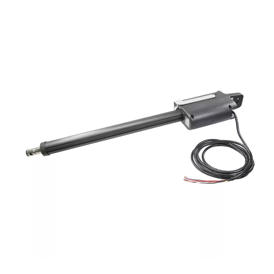
- Page 1 Vehicular Swing Gate Operator Nice Gate Operators Titan 912L The Titan 912L Gate Operator is intended for use with vehicular swing gates. The Titan 912L Gate Operator can be used in Class I, Class II and Class III applications. Revision 5.1.0.0_6-2017 Part# 10001700...
- Page 2 This page intentionally left blank.
-
Page 3: Table Of Contents
TABLE OF CONTENTS 5 - INSTALLATION PROCEDURES CAUTIONS AND NOTES 5.1 - Pivot arm installation EXTREMELY IMPORTANT Figure 5 - 1 P ULL TO O P EN INS TALLATIO N DEFINITIONS COMPLIANT TO UL325 Figure 5 - 2 V ERTICAL P IV O T P O S ITIO N 5.2 - Push to open installation 1- OVERVIEW Figure 5 - 3 P US H TO O P EN INS TALLATIO N... -
Page 4: Cautions And Notes
The Titan 912L swing gate operator delivers the next generation of easily installed, configured and maintained swing gate operators from Nice. With a maximum gate capacity of 600 lbs and 20 ft, this operator has a key lockable manual release, easily accessible limit switch settings as well as simple in-the-field maintenance and repair. -
Page 5: Gate Latches
This swing gate actuator is intended for those locations where vehicle traf- (gate). The Titan 912L actuator is only to be used in conjunction with Nice brand control boards. If the gate, actuator and control system are not fully... -
Page 6: Gate System Safety Devices
3.5 - Establish the location 4.1 - Follow Instructions 4.2 - Intended usage THIS ACTUATOR IS INTENDED FOR USE WITH VEHICULAR SWING GATES ONLY, WHEN COMBINED WITH A NICE BRAND 3.6 - Read and follow all instructions CONTROL BOARD. 3.7 - Keep children away 4.3 - Warnings, cautions and notes... - Page 7 4.3.53 All gate systems must utilize a monitored contact or non-contact presence detection sensor. 4.3.55 Hardwired contact or non-contact sensors to signal the gate actuator of entrapment conditions are recommended.
-
Page 8: Installation Procedures
5 - INSTALLATION PROCEDURES 5.1 - Pivot Arm Installation IMPORTANT - Never weld parts to the gate or posts when the operator circuit board is powered. Doing so may damage the board beyond repair. PULL TO OPEN INSTALLATION - PIVOT ARM INSTALLATION - Location of Pivot Point The following instructions provide up to 105°... -
Page 9: Push To Open Installation
5.2 - Push to open installation PIVOT ARM INSTALLATION - Location of Pivot Point Measurements are taken from the center of pivot of the gate hinge. The pivot arm needs to be securely mounted to the hinge post or equivalent mounting surface. It is recommended to weld the pivot arm to a metal post. -
Page 10: Manual Release/Manual Operation
5.4 - Manual release/manual operation Manual Release Disengage 1. Lift rubber key cover and insert key into lock and rotate 90° clockwise. 2. Lift handle 3. Actuator is now Disengaged Manual Release in (manual operation is possible). Disengaged Position 90° FIGURE 5-6 MANUAL RELEASE DISENGAGE Manual Release Re-engage 1. -
Page 11: Titan Actuator Wiring
5.5 - Titan actuator wiring THE FOLLOWING SECTION NEED ONLY BE USED FOR REWIRNG IN THE EVENT OF A DESIRED LONGER OR SHORTER CABLE LENGTH. Using the supplied key, unlock the manual release handle. Lift upwards on the release handle as shown. FIGURE 5 - 8 MANUAL RELEASE HANDLE With the release handle up, remove the screws from the limit cover and remove the cover. -
Page 12: Control Board Wiring
5.6 - Control board wiring 1050 Control Board FIGURE 5 - 11 WIRING DIAGRAM FOR 1050 CONTROL BOARD 936 Control Board FIGURE 5 - 12 WIRING DIAGRAM FOR 936 CONTOL BOARD... -
Page 13: Limit Switch Adjustment
5.7 - Limit switch adjustment BEFORE continuing with this section, make sure to have If the location of the gate is not the location desired, engage the manual release,move the gate to the position desired and the MANUAL for the contol board specific to this disengage the manual release, then repeat step 12. -
Page 14: General Layout And Safety Access
6- GENERAL LAYOUT AND SAFETY ACCESS Entrapment Protection Inputs - Typical Installation Diagram Utilizing Loop Sensors and Photocells Loop (Safety) Outside Gate 4’ Min. from closed gate 4’ Min. from closed gate Loop (Shadow) Photo 2 Photo 2 4’ Min. from open gate Loop (Safety) Loop (Exit) FIGURE 6 -1 LAYOUT FOR IN-GROUND LOOPS... -
Page 15: Accessories And Sensors
SECTION 7 - ACCESSORIES AND SENSORS EXTERNAL ENTRAPMENT PROTECTION Non-contact and contact sensors must be installed individually or in combination with each other to provide external entrapment protection. Care should be exercised to reduce the risk of nuisance tripping, such as when a vehicle trips the sensor while the gate is still moving, and one or more contact sensors shall be located where the risk of entrapment or obstruction exists, such as the perimeter reachable by a moving gate or barrier. -
Page 16: Inspection And Operation
9 - EMERGENCY VEHICLE ACCESS 8- INSPECTION AND OPERATION Proper inspection of all equipment is required to ensur e continuous functionality, safety and to ensure reliable operation in all weather conditions. Inspect electrical assemblies and wiring installations for damage, general condition, and proper functioning to ensure the continued satisfactory operation of the electrical system.
Need help?
Do you have a question about the Titan 912L and is the answer not in the manual?
Questions and answers