Nice Mercury 310 Installation & Reference Manual
Hide thumbs
Also See for Mercury 310:
- Quick start installation manual (2 pages) ,
- User manual (26 pages)

Related Manuals for Nice Mercury 310


Summary of Contents for Nice Mercury 310
- Page 1 Mercury 310 SolarBOX and ACBox with Mercury 310 Controller Controller - Installation reference manual www.ApolloGateOpeners.com | (800) 878-7829 | Sales@ApolloGateOpeners.com...
-
Page 2: Table Of Contents
Mercury 310 Automated Gate System Installation and Programming Manual CONTENTS CONTENTS 10.2 SAFETY SENSOR INPUTS ...54 1: INTRODUCTION ........3 10.2.1 Auto Sensor Scan 54 10.2.2 Manual Sensor Scan / Clear 54 OVERVIEW ........3 10.2.3 Sensor Activation (10K / BlueBUS) CONTROL BOXES ......4 10.3... -
Page 3: 1: Introduction
1.1 OVERVIEW There are four kits available using the Mercury 310 controller, as shown in the table below. These are described in greater detail on the following pages. MERCURY 310 KITS... -
Page 4: Control Boxes
CONTROL BOX ACBOX310 Control Box SolarBOX310 Control Box ACBOX310 Control Box Parts Part Number Description AC Powered ACBOX w/ Mercury 310 controller ACBOX310 • Apollo 816-1 Linear actuator (one type per installation) • TITAN 912L-1 Multi-channel plug-in 433Mhz receiver module... -
Page 5: Acutators And Accessories
Mercury 310 Automated Gate System Installation and Programming Manual 1.3 MERCURY 310 ACUTATORS AND ACCESSORIES LINEAR ACTUATOR Each kit contains one of the two actuators shown below. Apollo 816 TITAN 912L NOTICE Actuator installation instructions are not included in this manual. Download actuator manuals from: •... -
Page 6: 2: Important Safety Information
Mercury 310 Automated Gate System Installation and Programming Manual 2: IMPORTANT SAFETY INFORMATION SAFETY MESSAGES IMPORTANT SAFETY INSTRUCTIONS The safety messages below inform you about potential Hazards, associated with automatic gates, can hazards that can result in injury. Safety messages specifi cally... - Page 7 Mercury 310 Automated Gate System Installation and Programming Manual WARNING To reduce the risk of injury or death: 1. READ AND FOLLOW ALL INSTRUCTIONS. 2. Never let children operate or play with gate controls. Keep the remote control away from children.
- Page 8 Mercury 310 Automated Gate System Installation and Programming Manual VEHICULAR TRAFFIC ONLY WARNING This automatic gate operator is not designed nor is it intended for pedestrian traffi c. Vehicular gate operators must by their nature be powerful to function reliably. This power can cause injury or death. Accordingly, direct all pedestrian traffi c to a separate walk-through gate.
- Page 9 8 ft (2.44 m) above grade. SENSORS An existing gate latch shall be disabled when a manually Most Nice | HySecurity gate operators are equipped with a operated gate is retrofitted with a powered gate operator. Type A, Inherent Entrapment Sensor (IES). UL 325 Safety...
- Page 10 Refer to UL website at www.ul.com most up-to-date list of gate operator safety standards (UL damage. 325). Mercury 310 controller can monitor 10k sensors as TYPE A ENTRAPMENT PROTECTION: In Type A well as BlueBus photo eyes. entrapment protection, the controller monitors the electrical...
- Page 11 The following sensors have been tested with Nice | HySecurity gate operators by an independent The sensors shown in the table below have been tested with Nice | HySecurity gate operators by an independent laboratory laboratory and certified to comply with UL 325 7th Edition. Select sensors from this list and certifi ed to comply with UL 325 7th Edition.
- Page 12 Mercury 310 Automated Gate System Installation and Programming Manual To reduce risk of fi re or injury to persons: ELECTRICAL SAFETY Turn gate operator and all circuit Observe polarity between batteries and charging circuit. breakers OFF before performing Never mix battery sizes, types, or brands. Charging circuit...
- Page 13 Mercury 310 Automated Gate System Installation and Programming Manual of recycling metal and plastic. Using a metal and plastic MAINTENANCE OF GATE SYSTEMS recycling center promotes energy cost savings. To keep your automated gate system performing both safely and reliably it is important to ensure that the components of that system are functioning properly.
-
Page 14: 3: Installation Safety
• The gate being modified should be level and plumb and the gate should open easily and evenly. • Nice swing gate systems are NOT intended for installation on an incline. • These instructions assume actuator(s) has been installed per the applicable actuator installation manual. - Page 15 Mercury 310 Automated Gate System Installation and Programming Manual ACBOX310 Installation and AC Power Wiring Instructions www.ApolloGateOpeners.com | (800) 878-7829 | Sales@ApolloGateOpeners.com...
-
Page 16: 5: Acbox310 Installation
Mercury 310 Automated Gate System Installation and Programming Manual 5: ACBOX310 INSTALLATION To open the front cover, unlatch the two door fasteners and swing to the left. To open the internal panel to access the accessory mounting area and power supply, grip and pull at top of controller panel to disengage it from the magnet, then swing panel to left (see image below). - Page 17 Mercury 310 Automated Gate System Installation and Programming Manual Install ACBOX310 Mount control box on same side as primary actuator (for dual gate systems, the same side as the actuator with shorter harness) and at least six feet away from pivot arm or any moving part of the gate (see image below).
-
Page 18: Earth Ground
Mains Power Supply ACBOX310 Power Diagram The controller and linear actuator motors will run from the batteries during an AC power failure. The Mercury 310 controller itself operates ONLY on DC power. WARNING FOLLOW ALL SAFETY WARNINGS, AS FOLLOWS, WHEN INSTALLING AC POWER: •... -
Page 19: Wire Run Sizing
(140m) (213.3m) (350.5m) (548.6m) (54.8m) WARNING Mercury 310 controller accepts low voltage (<24VDC) power only. 5.1.3 Power Supply Wiring Access the power supply by opening the front cover, then pulling open the controller panel from the magnet. Front Cover Open... - Page 20 Mercury 310 Automated Gate System Installation and Programming Manual ACBOX310 Power Wiring NOTICE The power supply module must first be removed from the chassis before it can be wired. 1. Ensure all power sources are disconnected from the ACBOX310 and remove the battery leads from the Mercury 310 controller.
- Page 21 Mercury 310 Automated Gate System Installation and Programming Manual 3: ACBOX310 Power Wiring (Cont.) (Continued) 4. Run the AC source line through cord grip under power supply module and secure cord grip (Detail A). 5. Use wire nuts to connect AC wires to power supply wires as shown below in the illustration (Detail A), schematic (Detail B), and wiring table.
- Page 22 UL325 to be visible from both sides of gate! Ensure Audio Alarm Connection Check to ensure the factory wired connection between audio alarm (siren) and Mercury 310 controller is secure (see illustration below). The audio alarm is installed in the bottom of the chassis and used for the following: Signals a hard shutdown of the system, which is triggered by two consecutive entrapment events.
- Page 23 Mercury 310 Automated Gate System Installation and Programming Manual SolarBOX310 Installation and Solar Panel Wiring www.ApolloGateOpeners.com | (800) 878-7829 | Sales@ApolloGateOpeners.com...
-
Page 24: 6: Solarbox310 Installation
Mercury 310 Automated Gate System Installation and Programming Manual 6: SOLARBOX310 INSTALLATION To remove the front cover, unlock (if locked) from the padlock hasp, then swing out cover and pull it downward to remove from the chassis (below). NOTICE The SolarBOX310 comes factory wired as follows:... - Page 25 Mercury 310 Automated Gate System Installation and Programming Manual Install SolarBOX310 1. Mount the control box on the same side as the primary actuator (for dual gate systems, the same side as the actuator with shorter harness) and at least six feet away from pivot arm and moving parts of the gate (see below).
-
Page 26: Solarbox310 Power
Mercury 310 Automated Gate System Installation and Programming Manual 6.1 SOLARBOX310 POWER 6.1.1 Introduction and Warnings The SolarBOX310 features a solar panel and backup battery charging capability. The basic power flow through the SolarBOX310 system is displayed in the diagram below:... - Page 27 In the southern hemisphere orient panel to face north. See images below. 3. To prepare for wiring to the Mercury 310 controller, cut off two battery lugs from the end of the solar panel wires, strip the wires back 3/8-7/16" (10-11mm), and...
- Page 28 Ensure Audio Alarm Connection Check to ensure a connection of the audio alarm (siren) to the Mercury 310 controller per the illustration below. The audio alarm is installed in the bottom of the chassis and used for the following: Signals a hard shutdown of the system, which is triggered by two consecutive entrapment events.
- Page 29 IMPORTANT NOTICE! This section only provides instructions for wiring the Apollo 816 and TITAN 912 actuators to the Mercury 310 controller, but NOT the mechanical installation of the actuators to the gate. For mechanical installation instructions, refer to separate linear actuator installation...
-
Page 30: 7: Linear Actuators
Mercury 310 Automated Gate System Installation and Programming Manual 7: LINEAR ACTUATORS Install Linear Actuator and Run Cables 1. Refer to the linear actuator installation manual for the one used in the system and install (see note and links on previous page). - Page 31 Mercury 310 Automated Gate System Installation and Programming Manual TITAN 912L Linear Actuator Wiring SINGLE GATE DUAL GATE Apollo 816 Linear Actuator Wiring SINGLE GATE DUAL GATE www.ApolloGateOpeners.com | (800) 878-7829 | Sales@ApolloGateOpeners.com...
- Page 32 Mercury 310 Automated Gate System Installation and Programming Manual (This page intentionally blank) www.ApolloGateOpeners.com | (800) 878-7829 | Sales@ApolloGateOpeners.com...
- Page 33 Mercury 310 Automated Gate System Installation and Programming Manual Mercury 310 Controller Installation and Operating Instructions Applies to: • ACBOX310 • SolarBOX310 www.ApolloGateOpeners.com | (800) 878-7829 | Sales@ApolloGateOpeners.com...
-
Page 34: 8: Programming And Setup
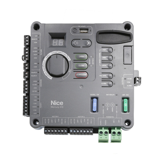
Mercury 310 Automated Gate System Installation and Programming Manual 8: PROGRAMMING AND SETUP Refer to the illustration below for identification of controls featured on the Mercury 310 controller. For operating and programming instructions, refer to the following pages. Gate Control Buttons... -
Page 35: Limit Learn Procedure
Installation and Programming Manual 8.1 LIMIT LEARN PROCEDURE After the control box and linear actuator has been installed and wired, the Mercury 310 controller must be programmed to recognize the gate mechanical limits, so that when the gate is operated, the controller knows when to stop at the mechanically set limit of travel. - Page 36 (display will show 10. After the Limit Learn procedure is finished, the Mercury 310 controller automatically enters Standby Mode. Refer to the next page for more information, then proceed to the next Section (Function Knob Settings).
-
Page 37: Standby Mode
8.2 STANDBY MODE Two seconds (2s) after limits are learned in the Mercury 310 controller, the controller automatically enters Satndby Mode. Standby Mode puts the board into a “low power mode” when it’s not in use. This is a significant power saving feature for solar panel applications. -
Page 38: Function Knob Settings
Mercury 310 Automated Gate System Installation and Programming Manual 8.3 FUNCTION KNOB SETTINGS Use the function knob to select the gate parameters for Force, Close Timer, and Leaf Delay per the instructions 2, 3, and 4. Force Setting The Force setting adjusts the amount of force the gate will exert on an immovable object before it will initiate a “Hard Shutdown”... - Page 39 Mercury 310 Automated Gate System Installation and Programming Manual Leaf Delay Setting In a dual gate system, this setting sets a slight delay in gate response of the two gate “leafs”. It has no effect on a single gate installation. A setting of 0 turns this feature OFF.
-
Page 40: Accessory Installation
Mercury 310 Automated Gate System Installation and Programming Manual 8.4 ACCESSORY INSTALLATION Accessories, such as loop detector boards, may be installed onto the rear panal of the ACBOX310 behind the controller (see IMAGE 9-2). Drill holes and/or use appropriate hardware to affix the accessories inside the enclosure. - Page 41 Mercury 310 Automated Gate System Installation and Programming Manual Install OXI Radio Module To install the OXI receiver, perform the following steps: 1. Ensure power to the controller is OFF. 2. Connect supplied antenna wire to terminal 1 of receiver (IMAGE 19-1, DETAIL A).
-
Page 42: Oxi Radio Programming
Mercury 310 Automated Gate System Installation and Programming Manual 8.5 OXI RADIO PROGRAMMING If OXIBD/A receiver module is installed, program transmitters (remote controls) for gate operation as described: IMPORTANT NOTICE Transmitters (remote controls) must be “learned” by the OXIBD/A radio receiver before other radio accessories (i.e. -
Page 43: Deleting Transmitters
Mercury display. Delete SINGLE Button from Transmitter: Press and hold any one of three radio channel buttons on the Mercury 310 controller for at least three (3) seconds until (Remote Delete Button) is displayed, then press the button on the remote to be deleted. -
Page 44: Firmware Update
The USB drive being used to update the firmware should have only one file version of the Mercury 3xx series firmware in the root directory. 3. Press and hold the F/W Update button on the Mercury 310 controller for about 5 seconds. The display will show "... -
Page 45: 9: Controller Operation
Mercury 310 Automated Gate System Installation and Programming Manual 9: CONTROLLER OPERATION Refer to the illustration below for identification of controls featured on the Mercury 310 controller. For operating and programming instructions, refer to the following pages. Gate Control Buttons... -
Page 46: Gate Control Buttons
Mercury 310 Automated Gate System Installation and Programming Manual 9.1 GATE CONTROL BUTTONS The OPEN, CLOSE, and STOP/CLEAR buttons are used to operate the gate from the control box. Each is described below. OPEN Button Press and release to open the gate. -
Page 47: Power Status Leds
Mercury 310 Automated Gate System Installation and Programming Manual 9.2 POWER STATUS LEDS The power indication LEDs display the power status for the solar, DC, and battery power sources, and each is described below. Battery Health LED LED: ’ Glows solid when battery power OK. -
Page 48: Fail-Safe & Alarm Buttons
(2) seconds after the gate starts moving, then turn off. CAUTION The alarm connected to the Mercury 310 Controller should never be disconnected! This alarm functions as the entrapment alarm and is a requirement under UL325 requirements. -
Page 49: 10: Inputs And Outputs
10: INPUTS AND OUTPUTS Refer to the illustration below for identification of inputs and outputs featured on the Mercury 310 controller, and on the next page for an example of accessories available. For a description of functions and wiring, refer to the following pages. - Page 50 Mercury 310 Automated Gate System Installation and Programming Manual WARNING Radio/Remote Disconnect the operator from power (Step-By-Step input for misc. remote devices) (both DC/Solar & Battery) when installing Nice BlueBUS any accessory or external entrapment Photo Eyes sensor. Transmitter & receiver bus, no polarity, up to 6 pairs 2 open direction &...
-
Page 51: Control Inputs
Mercury 310 Automated Gate System Installation and Programming Manual 10.1 CONTROL INPUTS The Control Inputs, which are used to control some Mercury 310 gate operations, are listed below and described on the following pages: ’ Remote/Radio Input ’ Guard station Input ’... - Page 52 Mercury 310 Automated Gate System +12 VDC Installation and Programming Manual N.O. REMOTE INPUT 10.1.2 Guard Station Input (STEP MODE) N.O. OPEN = Open Input (N.O.) N.O. GUARD CLOSE = Close Input (N.O.) STATION N.C. STOP = Stop Input (N.C.) COM = Common (GND) N.O.
-
Page 53: Fire Input 5
(STEP MODE) N.O. Mercury 310 Automated Gate System N.O. GUARD Installation and Programming Manual N.C. STATION 10.1.3 Fire Input N.O. FIRE FIRE = Emergency Access Input (N.O.) DEPT. COM = Common (GND) The fire input is meant to allow emergency personnel the ability to open the gate in an emergency situation BlueBUS without needing assistance. -
Page 54: Safety Sensor Inputs
10.2.1 Auto Sensor Scan When power is applied to the Mercury 310 controller, it performs a scan for connected external entrapment sensors at the sensor inputs and “learns” the sensor by registering it in an internal sensor registry. -
Page 55: Sensor Activation (10K / Bluebus)
Mercury 310 Automated Gate System Installation and Programming Manual The following section describes the behavior of the gate when the 10K and BlueBUS open and closed sensors are activated. 10.2.3 Sensor Activation (10K / BlueBUS) Activation of an open-direction or close-direction 10K or BlueBUS sensor input will stop an opening gate within two seconds and reverse it toward the opposite direction until the limit is reached. -
Page 56: Bluebus Input
STATION N.C. Mercury 310 Automated Gate System N.O. Installation and Programming Manual FIRE DEPT. 10.3 BLUEBUS INPUT BlueBUS = BlueBUS Photo eye inputs BlueBUS N.O. Nice BlueBUS photo eyes offer useful features, such as: N.O. Up to six (6) BlueBUS photo eye pairs may be wired together along SAFETY ’... - Page 57 Mercury 310 Automated Gate System Installation and Programming Manual NOTICE ’ To remove BlueBus sensors from the controller sensor registry: unplug sensors, then perform a registry clear by pressing and holding the Stop/Clear button for five (5) seconds, after which the sensors are relearned.
-
Page 58: Ω Sensor Inputs
7. Test the function of each sensor according to manufacturers instructions. NOTICE Example 10K Ω: EMX IRB Motor 1 The Mercury 310 controller requires sensors with 10K terminated MON Photo Eye outputs to meet the monitoring requirements of UL325. Dual Direction 10K Sensor Wiring... -
Page 59: Emx Irb-Ret (Photo Eye) Wiring
Mercury 310 Automated Gate System Installation and Programming Manual EMX IRB-MON (Photo Eye) Wiring 1 = OFF 2 = OFF 3 = ON 4 = ON NOTICE Wiring shown is for sensor in the open-direction. For a close-direction sensor, use the Close input. -
Page 60: Seco-Larm Enforcer Retro-Reflective (Photo Eye)
Mercury 310 Automated Gate System Installation and Programming Manual Seco-Larm Enforcer Retro-Reflective (E-931-S50RRGQ) (Photo Eye) Wiring 12-30V DC/AC Relay Tamper 60Hz, 100mA (Non-Polarity) N.C. N.O. COM. N.C. NOTICE Wiring shown is for sensor in the close-direction. For an Mercury 310 Controller open-direction sensor, use the Open input. -
Page 61: Emx Wel200 (Edge Sensor) Wiring
Mercury 310 Automated Gate System Installation and Programming Manual EMX WEL200 (Edge Sensor) Wiring NOTICE ’ Set board as shown in red boxes per diagram. Jumpers are three pin type, and placed LOWER as indicated for 10K operation. Dashed lines indicate the secondary wiring connections if an additional sensor is wired to the input. -
Page 62: Loop Inputs
Control (Exit) LOOPS The Mercury 310 is capable of three types of loop response: ’ Obstruction: Keeps a gate open if activated, OR if a gate is closing, reverses it to open. No effect on an opening gate. Motor 1 ’... - Page 63 Mercury 310 Automated Gate System Installation and Programming Manual 10.5.3 Exit Loop Input The Exit Loop input is used to open a fully closed gate for a vehicle, open a closing gate to prevent the gate from hitting a vehicle, or to prevent an open gate from closing onto a vehicle. Refer to loop examples below.
-
Page 64: Loop Installation
Mercury 310 Automated Gate System Installation and Programming Manual 10.6 LOOP INSTALLATION NOTICE The following are general instructions for installing generic vehicle loops detectors. If installing loop detectors, the manufacturer’s instructions should have priority over these guidelines. 10.6.1 Vehicle Detectors And Loops A vehicle detector passes a small current flow through the “loop”... -
Page 65: Detector Logic
Loop Sealant 10.6.3 Detector Logic Nice recommends that vehicle detectors be used for free open and obstruction sensing logic only. Because of their slower speeds, closing logic is a poor choice for security gate systems. Since there are several ways that the gate may be left standing open and because there is a loss of safety, our circuit has not been designed to accommodate “detect to close”... -
Page 66: Loop Layout (Dual Swing/Titan)
Mercury 310 Automated Gate System Installation and Programming Manual 10.6.5 Loop Layout Example (Dual Swing/TITAN) PUBLIC SIDE This layout illustrates a Access Control ENTER EXIT bi-directional traffic system with Device controlled access entry (card (Card reader, etc.) reader, radio control, etc.) and a Minimum 6 feet free exit loop. -
Page 67: Linear Actuator Inputs
Mercury 310 Automated Gate System Installation and Programming Manual 10.7 LINEAR ACTUATOR INPUTS Apollo 816 Linear Actuator Wiring TITAN 912L Linear Actuator Wiring Linear Actuator Input Functions POS# MOTOR FUNCTION POS# MOTOR FUNCTION Motor Power (+ or -) Motor Power (+ or -) -
Page 68: Power Inputs
Mercury 310 Automated Gate System Installation and Programming Manual 10.8 POWER INPUTS DC/SOL+ = High Current DC/Solar Input (Positive) DC/SOL- = High Current DC/Solar Ground (Negative) BAT+ = +12VDC Battery Input (Positive) BAT- = Battery Ground (Negative) Battery Input: Must be a 12VDC BATTERY sealed lead acid (SLA) battery. -
Page 69: Power Outputs
Mercury 310 Automated Gate System Installation and Programming Manual 10.9 POWER OUTPUTS 12VDC power outputs are provided at four locations, as shown below for powering additional accessories and sensors. Two of the power outputs switch off when the controller enters Standby Mode and the other two outputs remain powered during Standby Mode, as shown below. -
Page 70: 1: Manual Release
Mercury 310 Automated Gate System Installation and Programming Manual 10.10 ACTUATOR MANUAL RELEASE INSTRUCTIONS To manually open the gate in the event of a full power outage, follow the instructions in this section according to the type of actuator in your kit. The Apollo 816 linear actuator instructions are below and the TITAN 912L linear actuator instructions are on the next page. - Page 71 Mercury 310 Automated Gate System Installation and Programming Manual TITAN 912L Linear Actuator Manual Release Lift up the rubber key cap (See illustration below). Insert key and turn 90° clockwise. Lift up the mechanical release. After mechanical release is opened, the actuator arm can now be freely extended, and the gate can now be moved by hand.
- Page 72 Mercury 310 Automated Gate System Installation and Programming Manual (This page inentionall blank) www.ApolloGateOpeners.com | (800) 878-7829 | Sales@ApolloGateOpeners.com...
- Page 73 Mercury 310 Automated Gate System Installation and Programming Manual Mercury 310 Appendix www.ApolloGateOpeners.com | (800) 878-7829 | Sales@ApolloGateOpeners.com...
-
Page 74: 11: Error, Stop, And Led Codes
Mercury 310 Automated Gate System Installation and Programming Manual 11: ERROR, STOP, AND LED CODES Error Codes Error codes are very useful for communicating information to your gate installer in the event of a gate error. When there is an error, the display will alternately flash and a two number code, as shown in the Display column in the table below. - Page 75 Mercury 310 Automated Gate System Installation and Programming Manual Error Codes (Continued) 24V Power Supply Failure Defective component. (Only for Mercury 500 series) Lock fuse failure Excessive current draw. (Only for Mercury 500 series) Open & close limits active same time.
-
Page 76: 12: Solar Requirements
Mercury 310 Automated Gate System Installation and Programming Manual 12: SOLAR REQUIREMENTS Calculating Solar Requirements 1. Estimate the gate traffic measured in open/close cycles per the table below. Solar Panel Watt/Cycle Chart 1-10 1-20 1-40 1-60 1-80 80+ DAILY CYCLES... -
Page 77: 13: Maintenance
Mercury 310 Automated Gate System Installation and Programming Manual 13: MAINTENANCE The table below lists maintenance procedures that the gate installer should perform over time. It is the responsibility of the end user to ensure maintenance is performed by an appropriate automated gate uninstaller professionals. -
Page 78: 14: Troubleshooting
Mercury 310 Automated Gate System Installation and Programming Manual 14: TROUBLESHOOTING Troubleshooting Procedures Problem Possible Solution • Check the 10K sensor input on the gate controller Gate opens a short • Ensure limits are properly set distance, then stops and •... -
Page 79: 15: Installation Checklist
Mercury 310 Automated Gate System Installation and Programming Manual 15: INSTALLATION CHECKLIST The installer and customer must each ensure that all of the following actions have been completed. Left box is for installer check off and the right box is for customer check off. -
Page 80: 16: Warranty
This warranty will be interpreted, construed, and enforced in all respects in the name plate of a manufacturer other than HySecurity or Nice and they are not a accordance with the laws of the State of Washington, without reference to its part of the base model.
Need help?
Do you have a question about the Mercury 310 and is the answer not in the manual?
Questions and answers
Where to install external button.