
Subscribe to Our Youtube Channel
Related Manuals for Nice PP7124


Summary of Contents for Nice PP7124
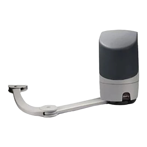
- Page 1 Nice PP7124 Swing gate opener EN - Instructions and warnings for installation and use...
-
Page 2: Table Of Contents
ENGLISH GENERAL SAFETY WARNINGS AND PRECAUTIONS Translation of the original instructions in full GENERAL SAFETY WARNINGS AND PRECAUTIONS 1.1 GENERAL WARNINGS WARNING! Important safety instructions. Observe CONTENTS all the instructions as improper installation may cause serious damages. GENERAL SAFETY WARNINGS AND PRECAUTIONS ..2 WARNING! Important safety instructions. -
Page 3: Installation Warnings
– Verify the system frequently, in particular check the ca- The PP7124 gearmotor is equipped with a control unit that man- bles and supports to detect any imbalances and signs ages its operation. -
Page 4: Installation
– verify that the mounting positions of the various devices are INSTALLATION protected against impacts and that the mounting surfaces are sufficiently sturdy – prevent any parts of the automation from being immersed in INSTALLATION water or other liquids 3.1 PRE-INSTALLATION CHECKS –... -
Page 5: Product Durability
3.2.1 Product durability The product’s durability is its average economic life value and is 250000 strongly influenced by the degree of severity of the manoeuvres: in other words, the sum of all factors that contribute to product wear. To estimate the durability of your automated device, proceed as follows: 200000 add the values of the items in “Table 1”... -
Page 6: Pre-Installation Works
3.4 PRE-INSTALLATION WORKS The figure shows an example of an automation system, constructed using Nice components. A Photocells on column Note 1 If the power supply cable is longer than 30 m, a cable B Gearmotor without control unit (model PP7224) with larger cross-sectional area (3 x 2.5 mm... -
Page 7: Installing The Gearmotor
3.5 INSTALLING THE GEARMOTOR use the fixing bracket (C), in the horizontal position, as a template to determine the position of the four fixing holes Incorrect installation may cause serious physical injury to the person working on the system or to its future users. - Page 8 fasten the straight arm (D) to the gearmotor using the unlock the gearmotor manually (see paragraph “Manually screw and relative washer provided unlocking and locking the gearmotor“) decide where to attach the bracket to the gate leaf, by extending the gearmotor arms as far as possible M8x55 It is important to position the bracket at the farthest point with respect to the position of the gearmotor.
-
Page 9: Adjusting The Mechanical Limit Switches
fasten the bracket to the gate leaf in the horizontal posi- 3.7 MANUALLY UNLOCKING AND LOCKING THE tion, using adequate screws (not supplied) GEARMOTOR The gearmotor is equipped with a mechanical unlocking device that can be used to open and close the gate manually. These manual operations should only be performed in case of a power outage, malfunctions or during the installation phases. -
Page 10: Electrical Connections
ELECTRICAL CONNECTIONS PP7124: loosen the cable clamp (B) ELECTRICAL CONNECTIONS 4.1 PRELIMINARY CHECKS All electrical connections must be made with the system disconnected from the mains electricity and with the back-up battery (if present) disconnected. -
Page 11: Wiring Diagram And Description Of Connections
Input for devices that control the partial opening 1 movement; it is possible to connect “Normally Open” contacts. Open output for gearmotor without control unit (PP7224) output for gearmotor with control unit (PP7124) inputs for antenna connection (on OXI receiver) 1 - 2 Note 1 Outputs “Flash”... -
Page 12: Final Checks And Start-Up
5.3 LEARNING OF THE MECHANICAL STOP FINAL CHECKS AND START-UP POSITIONS Once the connected devices have been learned, the mechan- It is advisable to position the leaf approximately halfway along FINAL CHECKS AND START-UP ical stop positions must be learned (maximum opening and its path before starting the automation check and start-up phas- maximum closing). -
Page 13: Learning In Automatic Mode
5.3.1 Learning in automatic mode To effect the manual learning procedure: simultaneously press and hold the and buttons To effect the automatic learning procedure: simultaneously press and hold the and buttons release the buttons when LED “L1” starts flashing (after roughly 1 second) release the buttons when LEDs “L3”... -
Page 14: Learning In Mixed Mode
LED “L6” flashes: position 1 of M2 5.4 CHECKING THE GATE MOVEMENT – to command and move motor 2 to position “1” (“Fig- ure 29”): press and hold the button. Once the position is reached, release the button to stop the manoeuvre –... -
Page 15: Testing And Commissioning
For all the above-mentioned documentation, Nice – ceeding 390N (roughly 40 kg) through its technical assistance service – provides lock the gearmotor the following: pre-completed forms. -
Page 16: Level 1 Programming (On-Off)
7.2 LEVEL 1 PROGRAMMING (ON-OFF) All the Level 1 functions are factory-set to “OFF” and can be modified at any time. To check the various functions, refer to “Table 5”. 7.2.1 Level 1 programming procedure The user has maximum 10 seconds to press the buttons consecutively during the programming procedure, after which time the procedure terminates automatically and memorises the changes made up to then. -
Page 17: Level 2 Programming (Adjustable Parameters)
7.3 LEVEL 2 PROGRAMMING (ADJUSTABLE PARAMETERS) All the Level 2 parameters are factory-set as highlighted in “GREY” in “Table 6” and can be modified at any time. The parameters can be set to a scale of 1 to 8. The check the value corresponding to each LED, refer to “Table 6”. 7.3.1 Level 2 programming procedure The user has maximum 10 seconds to press the buttons consecutively during the programming procedure, after which time the procedure terminates automatically and memorises the changes made up to then. - Page 18 LEVEL 2 FUNCTIONS (ADJUSTABLE PARAMETERS) Entry Parameter Set value Description (level) No discharge Level 1 - Minimum discharge (roughly 100 ms) Level 2 - ... Adjusts the duration of the “brief reversal” of both Motor Level 3 - ... motors, once the closing manoeuvre terminates, discharge after Level 4 - ...
-
Page 19: Special Functions
7.4 SPECIAL FUNCTIONS 7.4.3 Verifying the number of manoeuvres completed The “Maintenance notice” function can be used to verify the number of manoeuvres completed as a percentage of the set 7.4.1 “Move anyway” function limit. This function can be used to operate the automation even one or more some safety devices fail to work properly or are out of order. -
Page 20: Troubleshooting Guide
TROUBLESHOOTING... (troubleshooting guide) TROUBLESHOOTING GUIDE 8.1 ANOMALY LOG press the button to shift the flash- ing LED to “L8”, that is, the “entry LED” for the “List of The gearmotor allows for displaying any anomalies that oc- anomalies” parameter curred in the last 8 manoeuvres, for example, the interruption of press and hold the button. -
Page 21: Signals On The Control Unit
8.3 SIGNALS ON THE CONTROL UNIT The control unit has a series of LEDs, each of which can emit special signals both during regular operation and when an anomaly occurs. Table 9 TERMINAL LEDS ON THE CONTROL UNIT Status Meaning Possible solution BlueBus LED Check for the presence of power;... -
Page 22: Further Details (Accessories)
9.1.3 Photocells FURTHER INFORMATION To allow the control unit to recognise the devices connected (Accessories) through the “BlueBUS” system, these devices must be ad- dressed. FURTHER DETAILS (Accessories) This operation can be carried out by correctly positioning the 9.1 ADDING OR REMOVING DEVICES electrical jumper present in each device (also refer to the in- Once the automation has been assembled, it is possible to add struction manual of each device). -
Page 23: Learning Of Other Devices
The association between the radio receiver output and the com- 9.1.4 Learning of other devices mand executed by the motor is shown in “Table 11”: Normally the learning of devices connected to “BlueBUS” and the “STOP” input takes place during the installation stage; how- Table 11 ever, if new devices are added or old ones removed, the learn- OXI IN MODE I OR MODE II... -
Page 24: Connecting And Installing The Back-Up Battery
9.3 CONNECTING AND INSTALLING THE BACK- UP BATTERY The electrical connection of the battery to the con- trol unit must be made only after completing all the installation and programming stages, as the battery is an emergency power supply. To install and connect the battery: remove the cover (A) slide the battery (B) into its housing remove the plastic protection (C) with the aid of a screw-... - Page 25 To install the interface: remove the cover (A) place the interface (B) in the appropriate slot (C) on the control unit’s electronic board insert the cable (D) in the appropriate slot (E) on the in- terface. At this stage, the control unit can be powered again. For further information, consult the specific manu- als of the connected devices.
-
Page 26: Connecting The Solemyo Solar Energy System
9.6 CONNECTING THE SOLEMYO SOLAR For information on the “Solemyo” system, consult ENERGY SYSTEM the relevant instruction manual. To connect the “Solemyo” system: When the automation is powered by the “Solemyo” remove the cover (A) system, IT MUST NOT BE POWERED by the elec- remove the plastic protection (B) with the aid of a screw- tricity grid at the same time. -
Page 27: Product Maintenance
PRODUCT MAINTENANCE PRODUCT DISPOSAL The automation must be subjected to regular maintenance to PRODUCT MAINTENANCE PRODUCT DISPOSAL This product is an integral part of the operator and keep its safety level constant and guarantee long-lasting op- must therefore be disposed of with it. eration;... -
Page 28: Technical Specifications
TECHNICAL SPECIFICATIONS TECHNICAL SPECIFICATIONS All technical specifications stated in this section refer to an ambient temperature of 20°C (± 5°C). Nice S.p.A. reserves the right to apply modifications to the product at any time when deemed necessary, without altering its functions and intended use. - Page 29 TECHNICAL SPECIFICATIONS Description Technical specification PP7124 PP7224 OXI (version with antenna connector Radio receiver mounted) 8 ON-OFF functions and 8 adjustable functions (see “Level 1 programming Programmable functions (ON-OFF)” paragraph) Self-learning of the devices connected to the BlueBus output Self-learning of the type of “STOP” device (Normally Open, Normally Closed contact or 8.2 kΩ...
-
Page 30: Conformity
“partly completed machinery” Note - The contents of this declaration correspond to declarations in the official document deposited at the registered offices of Nice S.p.a. and in particular to the last revision available before printing this manual. The text herein has been re-edited for editorial purposes. A copy of the original declaration can be requested from Nice S.p.a. (TV) I. - Page 31 NOTES ENGLISH – 31...
- Page 32 NOTES 32 – ENGLISH...
-
Page 33: Instructions And Warnings For The User
INSTRUCTIONS AND WARNINGS FOR THE USER Before using the automation for the first time, ask the installer to Safety devices out of order: the automation can also be used explain the origin of any residual risks and take a few minutes when one or more safety devices are defective or out of order. - Page 34 Unlocking and manual movement The gate can only be unlocked once the leaf has come to a standstill. To unlock the device: raise the small cover insert the key (A) and turn it clockwise by 90° the gate leaf can now be moved manually to the desired position.
- Page 35 NOTES ENGLISH – 35...
- Page 36 Nice SpA Via Callalta, 1 31046 Oderzo TV Italy www.niceforyou.com info@niceforyou.com...
Need help?
Do you have a question about the PP7124 and is the answer not in the manual?
Questions and answers