Table of Contents
Advertisement
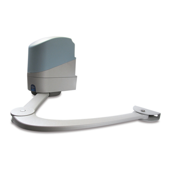
PopKit
For swing gates with leaves
up to 2 m, also with large
posts and lightweight
structures.
Version compatible with
the solar power system Solemyo.
Technical specifications
Power
(Vac 50 Hz)
Emergency power supply
Current absorbed
(line) (A)
Power absorbed
Protection level
Torque
Speed
(Rpm)
Opening time
Working temp.
(°C Min/Max)
Insulation class
Work cycle
Dimension
(mm)
Weight
* version without control unit
Utilisation limits
250
200
1
1,5
Max. gate length (m)
20
SYSTEMS FOR SWING GATES KIT PRICES 2010
Sophisticated electronics: slowdown,
obstacle detection system, can be linked
to the 8.2 KOhm resistive sensitive edge.
User-friendly: release with personalised
key designed.
Sturdy, aluminium, anti-shearing arm.
Always ready for use: continues to work
even during power failures using optional
(PS124) batteries that fit inside the motor.
PP7024
230
PS124
~1
75
(W)
44
(IP)
(Nm)
180
1.26-1.68
10
(s)
-20 ÷ +50
1
30
(%)
167x315x254
(kg)
21.6
The shape, the height of the gate
and the weather conditions
can considerably reduce the values
shown in the graph to the side.
2
Dimensions
PP7224*
-
3
167 mm
B
Exclusive functions: photo-test,
pedestrian gate, programmable input
for functions such as open, close,
photo2, open pedestrian and open partially.
Extra-small, shockproof body
with aluminium base.
254
545
Max. 250 mm
Max.
Min. 500 mm (90°)
Advertisement
Table of Contents

Related Manuals for Nice Pop Series


Summary of Contents for Nice Pop Series
- Page 1 PopKit For swing gates with leaves Sophisticated electronics: slowdown, Exclusive functions: photo-test, obstacle detection system, can be linked pedestrian gate, programmable input up to 2 m, also with large to the 8.2 KOhm resistive sensitive edge. for functions such as open, close, posts and lightweight User-friendly: release with personalised photo2, open pedestrian and open partially.
- Page 2 Anything which is not specified in these instructions is not allowed, any the NICE customer service department. The use of POP in these con- unspecified use may damage the product and place people and objects ditions can be dangerous.
- Page 3 1) Product description POP is a gearmotor for small and medium-sized swing gates. It • PP7024 with incorporated control unit and 230V power supply automates gates with leaves of a maximum 2m in length and 200 kg (The PP7024/V1 version has a 120V power supply.) in weight.
- Page 4 2.4) Mounting the motor bracket to the pillar (Fig. 6) Use screws which are suitable for the material the pillar is made of. Mount the bracket horizontally. 2.5) Assembly of the straight arm (Fig. 7) Use the M8x55 screw with its relative grower washer. Make sure the arm is positioned by making it come out of the front part. 2.6) Mounting the gearmotor (Fig.
- Page 5 4) Testing and commissioning These are the most important operations, designed to guarantee the what tests should be conducted based on the risk involved, and ver- maximum safety of the automation system. The testing procedure ify the compliance of the system with applicable regulations, legisla- can also be used as a periodic check of the devices that make up tion and standards, in particular with all the provisions of EN stan- the automation.
- Page 6 For swing gates Instructions and warnings for the fitter Istruzioni e avvertenze per l’installatore Instructions et recommandations pour l’installation Anweisungen und hinweise für den installateur Instrucciones j advertencias para el instalador Instrukcja dla instalatora...
- Page 10 PP7024 PP7224...
- Page 12 POA1 Control unit EN - Instructions and warnings for installation and use IT - Istruzioni ed avvertenze per l’installazione e l’uso FR - Instructions et avertissements pour l’installation et l’utilisation ES - Instrucciones y advertencias para la instalación y el uso DE - Installierungs-und Gebrauchsanleitungen und Hinweise PL -...
-
Page 13: Table Of Contents
Incorrect installation could cause serious physical injury. Read all parts of the manual carefully before starting work. If in doubt, interrupt installation and contact the Nice Service Centre for clarifications. • IMPORTANT! – Important instructions: keep this manual in a safe place to enable future product maintenance and disposal procedures. -
Page 14: Preliminary Checks For Installation
• Activation of the “PHOTO 1” pair of photocells stops both the opening and 2.3 - Electrical connections closing manoeuvres. IMPORTANT! • Activation of the “PHOTO2” pair of photocells (connected to the suitably pro- – All electrical connections must be made with the unit disconnected from grammed AUX input) has no effect during closing while they invert movement the mains power supply and with the buffer battery disconnected, if pres- during opening. -
Page 15: Initial Start-Up And Electrical Connections
When the “Everything in stand by” function is active, 1 minute after the end of a 2.4 - Initial start-up and electrical connections manoeuvre the control unit goes into “Everything in stand by”, turning off the Inputs IMPORTANT! – Connections must be made exclusively by qualified per- and Outputs to reduce consumptions. -
Page 16: Testing And Commissioning
TESTING AND COMMISSIONING DIAGNOSTICS These are the most important phases of automation set-up for ensuring maxi- The diagnostics LED P2 (fig. 2) indicates any problems or malfunctions re - mum system safety. The test can also be performed as a periodic check of vealed by the control unit during the manoeuvre. - Page 17 of the lower leaf motor compared with the upper one This is necessary in The P1, P2 and P3 buttons are used for all the programming phases, while the order to prevent the leafs from getting stuck. There is always a standard delay 5 LEDs (L1, L2…L5) indicate the selected parameter.
- Page 18 5.3.1 - Level one programming: functions has been selected, short flashes indicate the function has been deactivated; long flashes indicate the function has been activated. Press P3 to pass from At level 1, the functions can be enabled or disabled. At level one, LED P1 is part one programming to part two programming, and vice-versa.
- Page 19 TABLE C1 - Delete memory 01. Switch the power supply to the control box off, and wait until all the LEDs have gone off (remove fuse F1 if necessary) 02. Press P1 and P2 on the board down and keep them pressed down 03.
-
Page 20: Programming Diagrame
5.3.6 - Programming diagram This figure also shows the functions and parameters either as they were initially or following total memory deletion. The following figure shows the complete programming diagram of the functions and relative parameters. Normal operation Led P1 Slow flashing Photo Photo Step step... -
Page 21: Further Details: Accessories
the mechanical stops, therefore). This is considered as an obstacle and causes an inversion. To find out if the current sensitivity device has triggered, FURTHER DETAILS: accessories count how many times the Diagnostics LED flashes: 1 flash indicates that the current sensitivity device triggered on account of motor 1, 2 flashes indicate that this was caused by motor 2. -
Page 22: Technical Characteristics Of The Product
EC DECLARATION OF CONFORMITY Note - The contents of this declaration correspond to declarations in the last revision of the official document deposited at the registered offices of Nice Spa available before this manual was printed. The text herein has been re-edited for editorial purposes. -
Page 23: Product Description
smxi - smixs 0682 radio receiver The receiver features 4 outputs, all available on the underlying connector. To find out which function is performed by each output, see chapter 6.1. PRODUCT DESCRIPTION During the transmitter code memorisation phase, one of these two options may be chosen: Mode I - Table B1: Each transmitter button activates the corresponding out- SMXI and SMXIS are 4-channel radio receivers for control units equipped with... -
Page 24: Deleting All Transmitters
TECHNICAL CHARACTERISTICS OF THE PRODUCT WARNINGS: • All technical characteristics stated refer to an ambient temperature of 20°C (±5°C). • Nice S.p.a reserves the right to modify the product at any timee, while maintaining the same functionalities and intended use. • The range of the transmitters and the reception capacity of the receivers may be subject to interference that may alter their performance. -
Page 25: Images
Images Immagini Images Imágenes Bilder Zdjęcia Afbeeldingen... - Page 26 EN - E = Electric jumper DE - E = Brücke IT - E = Ponticello elettrico PL - E = Mostek elektryczny FR - E = Cavalier électrique NL - E = Elektrische ES - E = Conexión eléctrico geleidingsbrug 1 2 3 8 9 10 11 12 13 14 15 16...
- Page 27 Connection with “Everything in stand by” active (energy saving) IT - Collegamento con “Stand by tutto” attivo (risparmio energetico) FR - Connexion avec « Stand-by total » actif (économie d’énergie) ES - Conexión con “Stand by todo” activo (ahorro energético) Anschluss mit aktivem “Stand by - alles”...
- Page 28 Connection without “Everything in stand by” with “Phototest” IT - Collegamento senza “Stand by tutto” con “Fototest” FR - Connexion sans “Stand by todo” et avec « phototest » ES - Conexión sin “Stand by todo” con “Fototest” Ohne “Stand by - alles” und ohne “Phototest” PL - Połączenie bez funkcji “Stand by całego urządzenia”...
- Page 29 STEP BY STEP NC NO NO NC 12 V ~ 33 V max 5 W max 25 VA 8,2KΩ 8,2KΩ 8,2KΩ With “Everything in stand by” active connect terminal no. 8 and Bei aktivem “Stand by - alles”, die Klemme Nr. 8 und und nicht 11 not no.
- Page 31 Ph. +351.21.922.82.10 Ph. +39.049.87.01.05.1 Nice Australia infomarseille@fr.niceforyou.com Fax +351.21.922.82.19 Fax +39.049.87.07.63.8 Wetherill Park Australia info@pt.niceforyou.com infopd@niceforyou.com Ph. +61.(0)2.96.04.25.70 Nice France Rhône Alpes Fax +61.(0)2.96.04.25.73 Nice Roma Decines Charpieu France Nice Romania info@au.niceforyou.com Roma Italia Cluj Napoca Romania Ph. +33.(0)4.78.26.56.53 Ph. +39.06.72.67.17.61 Ph./Fax +40.(0)264.453.127...
Need help?
Do you have a question about the Pop Series and is the answer not in the manual?
Questions and answers