Advertisement
INSTRUCTION MANUAL
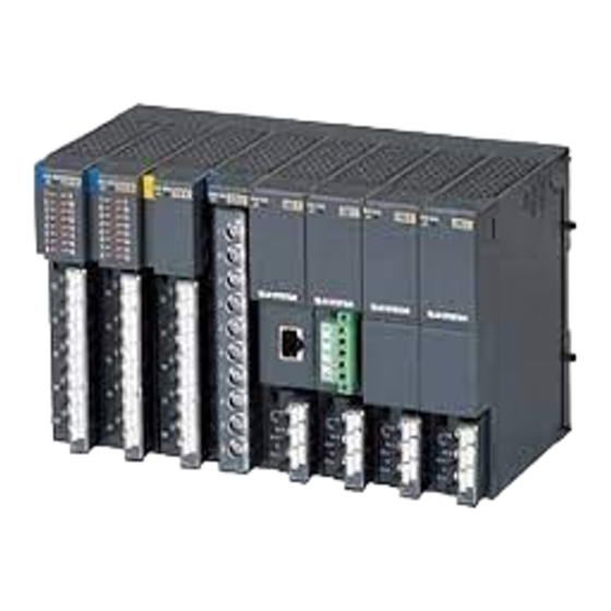
DC CURRENT OUTPUT MODULE
BEFORE USE ....
Thank you for choosing M-System. Before use, please check
contents of the package you received as outlined below.
If you have any problems or questions with the product,
please contact M-System's Sales Office or representatives.
■ PACKAGE INCLUDES:
DC current output module..................................................(1)
■ MODEL NO.
Confirm Model No. marking on the product to be exactly
what you ordered.
■ INSTRUCTION MANUAL
This manual describes necessary points of caution when
you use this product, including installation, connection and
basic maintenance procedures.
(4 points, isolated)
5-2-55, Minamitsumori, Nishinari-ku, Osaka 557-0063 JAPAN
Phone: +81(6)6659-8201 Fax: +81(6)6659-8510 E-mail: info@m-system.co.jp
MODEL
POINTS OF CAUTION
■ CONFORMITY WITH EU DIRECTIVES
• The equipment must be mounted inside the instrument
panel of a metal enclosure.
• The actual installation environments such as panel con-
figurations, connected devices, connected wires, may af-
fect the protection level of this unit when it is integrated
in a panel system. The user may have to review the CE
requirements in regard to the whole system and employ
additional protective measures to ensure the CE conform-
ity.
■ GENERAL PRECAUTIONS
• Before you remove the terminal block or mount it, make
sure to turn off the output signal for safety.
■ HOT SWAPPABLE MODULES
• It is possible to replace the module with the power sup-
plied, provided that the module is replaced with a module
of the same model number and that the same Installation
Base slot is used.
• Turn off output signals before replacing the module for
safety. Note that replacing multiple modules at once may
greatly change line voltage levels. We highly recommend
to replace them one by one.
■ UNUSED CHANNEL
• Set unused channels to "CH disabled" with PC Configura-
tor software (model: R30CFG). Otherwise, unused out-
puts left open are to be break status, setting a data error
at the PLC or other host devices.
■ ENVIRONMENT
• Indoor use.
• When heavy dust or metal particles are present in the
air, install the unit inside proper housing with sufficient
ventilation.
• Do not install the unit where it is subjected to continuous
vibration. Do not subject the unit to physical impact.
• Environmental temperature must be within -10 to +55°C
(14 to 131°F) with relative humidity within 10 to 90% RH
in order to ensure adequate life span and operation.
■ WIRING
• Do not install cables close to noise sources (relay drive
cable, high frequency line, etc.).
• Do not bind these cables together with those in which
noises are present. Do not install them in the same duct.
• Be sure to attach the terminal cover for safety.
■ AND ....
• The unit is designed to function as soon as power is sup-
plied, however, a warm up for 10 minutes is required for
satisfying complete performance described in the data
sheet.
R30YS4
EM-9006 Rev.1 P. 1 / 5
Advertisement
Table of Contents

Related Manuals for M-system R30YS4


Summary of Contents for M-system R30YS4
- Page 1 (4 points, isolated) BEFORE USE ..POINTS OF CAUTION Thank you for choosing M-System. Before use, please check ■ CONFORMITY WITH EU DIRECTIVES contents of the package you received as outlined below. • The equipment must be mounted inside the instrument If you have any problems or questions with the product, panel of a metal enclosure.
-
Page 2: Component Identification
COM3 No connection No connection COM4 No connection No connection No connection No connection No connection No connection No connection No connection EM-9006 Rev.1 P. 2 / 5 5-2-55, Minamitsumori, Nishinari-ku, Osaka 557-0063 JAPAN Phone: +81(6)6659-8201 Fax: +81(6)6659-8510 E-mail: info@m-system.co.jp... -
Page 3: Installation
Lock Tab 3) Tighten the base fixing screw using a screwdriver (stem length: 70 mm/2.76” or more) (torque 0.5 N·m). Base Fixing Screw EM-9006 Rev.1 P. 3 / 5 5-2-55, Minamitsumori, Nishinari-ku, Osaka 557-0063 JAPAN Phone: +81(6)6659-8201 Fax: +81(6)6659-8510 E-mail: info@m-system.co.jp... -
Page 4: Terminal Connections
Unused channels can be specified and set so on the PC Configurator Software (model: R30CFG) without needing to short at the field terminals. EM-9006 Rev.1 P. 4 / 5 5-2-55, Minamitsumori, Nishinari-ku, Osaka 557-0063 JAPAN Phone: +81(6)6659-8201 Fax: +81(6)6659-8510 E-mail: info@m-system.co.jp... -
Page 5: Wiring Instructions
In the case of wire breakdown, output error is detected. Then, the ERR LED blinks in red and the flag of error is set on the PLC etc. EM-9006 Rev.1 P. 5 / 5 5-2-55, Minamitsumori, Nishinari-ku, Osaka 557-0063 JAPAN Phone: +81(6)6659-8201 Fax: +81(6)6659-8510 E-mail: info@m-system.co.jp...
Need help?
Do you have a question about the R30YS4 and is the answer not in the manual?
Questions and answers