Table of Contents
Advertisement
Quick Links
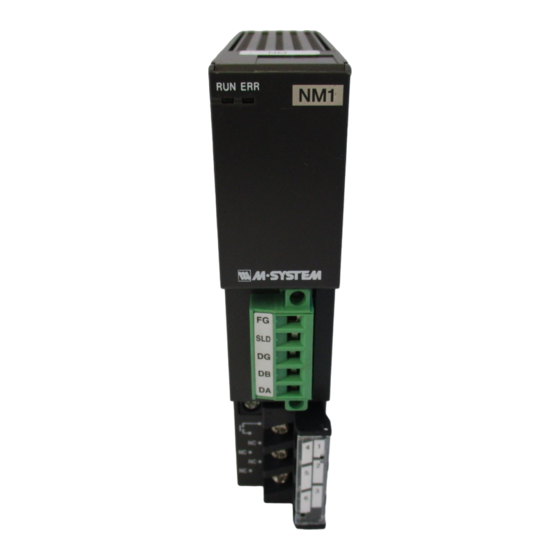
INSTRUCTION MANUAL
MODBUS INTERFACE MODULE
BEFORE USE ....
Thank you for choosing M-System. Before use, please check
contents of the package you received as outlined below.
If you have any problems or questions with the product,
please contact M-System's Sales Office or representatives.
■ PACKAGE INCLUDES:
Network interface module ..................................................(1)
Terminating resistor (110 Ω, 0.25 W) .................................(1)
■ MODEL NO.
Confirm Model No. marking on the product to be exactly
what you ordered.
■ INSTRUCTION MANUAL
This manual describes necessary points of caution when
you use this product, including installation, connection and
basic maintenance procedures.
POINTS OF CAUTION
■ CONFORMITY WITH EU DIRECTIVES
• The equipment must be mounted inside the instrument
panel of a metal enclosure.
• The actual installation environments such as panel con-
figurations, connected devices, connected wires, may af-
fect the protection level of this unit when it is integrated
in a panel system. The user may have to review the CE
requirements in regard to the whole system and employ
additional protective measures to ensure the CE conform-
ity.
■ HOT SWAPPABLE MODULES
• The module can be replaced while the power is ON. Be
sure to replace it when the module is not communicat-
ing with a host, as it may affect the system. Replacing
multiple modules at once may greatly change line voltage
levels. We highly recommend to replace them one by one.
■ POWER INPUT RATING & OPERATIONAL RANGE
• Locate the power input rating marked on the product and
confirm its operational range as indicated below:
100 – 120V AC rating: 85 – 132V, 47 – 66 Hz, approx. 20VA
200 – 240V AC rating: 170 – 264V, 47 – 66 Hz, approx. 20VA
24V DC rating: 24V ±10%, approx. 12W
■ GENERAL PRECAUTIONS
• DO NOT set the switches on the module while the power
is supplied. The switches are used only for maintenance
without the power.
■ ENVIRONMENT
• Indoor use.
• When heavy dust or metal particles are present in the
air, install the unit inside proper housing with sufficient
ventilation.
5-2-55, Minamitsumori, Nishinari-ku, Osaka 557-0063 JAPAN
Phone: +81(6)6659-8201 Fax: +81(6)6659-8510 E-mail: info@m-system.co.jp
MODEL
• Do not install the unit where it is subjected to continuous
vibration. Do not subject the unit to physical impact.
• Environmental temperature must be within -10 to +55°C
(14 to 131°F) with relative humidity within 30 to 90% RH
in order to ensure adequate life span and operation.
■ WIRING
• Do not install cables close to noise sources (relay drive
cable, high frequency line, etc.).
• Do not bind these cables together with those in which
noises are present. Do not install them in the same duct.
■ AND ....
• The unit is designed to function as soon as power is sup-
plied, however, a warm up for 10 minutes is required for
satisfying complete performance described in the data
sheet.
INSTALLATION
Use the Installation Base Model R3-BS, or Model R3-BSW
for free I/O address capability.
Before mounting the Network Interface Module onto the
Base, be sure to configure the module as explained below.
■ DATA ALLOCATION
The setting determines the data area size assigned to each
I/O module mounted on the base.
The data sent/received via Modbus is mapped according to
this setting.
See "COMPONENT IDENTIFICATION" and "MODBUS
I/O ASSIGNMENTS".
■ NODE ADDRESS & BAUD RATE, ETC.
See "COMPONENT IDENTIFICATION".
■ NETWORK SLOTS ON THE BASE
I/O 1
I/O 2
With Model R3-BS base, mount the I/O Modules from the
left end (I/O 1) to the right in order that the Network Mod-
ule assigns data areas from I/O 1.
Network Module(s) and Power Module are mounted basi-
cally at the right end though technically they could be
mounted in any position.
With Model R3-BSW base, there is no limitation in mount-
ing positions as I/O address can be assigned freely to each
module using rotary switches equipped on the base.
R3-NM1
I/O n
EM-8354 Rev.19 P. 1 / 8
Advertisement
Table of Contents

Related Manuals for M-system R3-NM1


Summary of Contents for M-system R3-NM1
- Page 1 Do not subject the unit to physical impact. • Environmental temperature must be within -10 to +55°C Thank you for choosing M-System. Before use, please check (14 to 131°F) with relative humidity within 30 to 90% RH contents of the package you received as outlined below.
-
Page 2: Component Identification
Note: Be sure to set unused SW6-6 through 6-8 to OFF. always be set to ‘Main’ (OFF). DUAL COMMUNICATION MAIN (*) SW3-1 EM-8354 Rev.19 P. 2 / 8 5-2-55, Minamitsumori, Nishinari-ku, Osaka 557-0063 JAPAN Phone: +81(6)6659-8201 Fax: +81(6)6659-8510 E-mail: info@m-system.co.jp... - Page 3 Refer to the users manual for the R3CON for detailed operation of the software program. ■ NETWORK MODULE SETTING PARAMETER SETTING RANGE DEFAULT SETTING Time (no communication time) 0.2 – 3200.0 (sec.) 3.0 (sec.) EM-8354 Rev.19 P. 3 / 8 5-2-55, Minamitsumori, Nishinari-ku, Osaka 557-0063 JAPAN Phone: +81(6)6659-8201 Fax: +81(6)6659-8510 E-mail: info@m-system.co.jp...
-
Page 4: Terminal Connections
Stripped length: 7 mm COMMUNICATION CABLE CONNECTIONS MODBUS MODBUS INTERFACE INTERFACE MODULE MODULE HOST PC TERMINATOR Tx+ / Rx+ Tx– / Rx– Rx– EM-8354 Rev.19 P. 4 / 8 5-2-55, Minamitsumori, Nishinari-ku, Osaka 557-0063 JAPAN Phone: +81(6)6659-8201 Fax: +81(6)6659-8510 E-mail: info@m-system.co.jp... - Page 5 Contents of the diagnostic data (2 bytes) Change ASCII Input Delimiter Delimiter character of ASCII message Force Listen Only Mode Force the slave into Listen Only Mode EM-8354 Rev.19 P. 5 / 8 5-2-55, Minamitsumori, Nishinari-ku, Osaka 557-0063 JAPAN Phone: +81(6)6659-8201 Fax: +81(6)6659-8510 E-mail: info@m-system.co.jp...
-
Page 6: Modbus I/O Assignments
For Coil (0X) and Inputs (1X), addresses 16 times assigned data areas (Data Allocation Type) are allotted with the Data Al- location Type ‘1’ and ‘4.’ With ‘8’ and ‘16,’ 64 (4 × 16) are automatically allotted. EM-8354 Rev.19 P. 6 / 8 5-2-55, Minamitsumori, Nishinari-ku, Osaka 557-0063 JAPAN Phone: +81(6)6659-8201 Fax: +81(6)6659-8510 E-mail: info@m-system.co.jp... - Page 7 Lower 16 bits are allocated from the lowest address to higher ones, higher 16 bits in turn. 32-bit data cannot be accessed using floating addresses. Lower 16 bits Higher 16 bits EM-8354 Rev.19 P. 7 / 8 5-2-55, Minamitsumori, Nishinari-ku, Osaka 557-0063 JAPAN Phone: +81(6)6659-8201 Fax: +81(6)6659-8510 E-mail: info@m-system.co.jp...
- Page 8 ‘0.’ Be sure to switch the setting back to ‘1’ before the communication is restored. 5) When both the main and the sub network modules are in communication, the output can be switched without delay. EM-8354 Rev.19 P. 8 / 8 5-2-55, Minamitsumori, Nishinari-ku, Osaka 557-0063 JAPAN Phone: +81(6)6659-8201 Fax: +81(6)6659-8510 E-mail: info@m-system.co.jp...
Need help?
Do you have a question about the R3-NM1 and is the answer not in the manual?
Questions and answers