Table of Contents
Advertisement
Quick Links
6H123-50 and 6H133-37 MicroLAN
SmartSwitch 6000 Interface Modules
9032276-04
User's Guide
Ethernet
6H123-50
C
C
C
C
C
C
C
C
O
O
O
O
O
O
O
O
N
N
N
N
N
N
N
N
N
N
N
N
N
N
N
N
1
1
2
2
3
3
4
4
10
10
COM
C
C
C
C
C
C
C
C
O
O
O
O
O
O
O
O
N
N
N
N
N
N
N
N
N
N
N
N
N
N
N
N
1
1
2
2
3
3
4
4
100
100
CPU
1
1
C
C
C
C
O
O
O
O
N
N
N
N
N
N
N
N
1
1
3
3
12
12
1
1
C
C
C
C
O
O
O
O
N
N
N
N
N
N
N
N
2
2
4
4
12
12
5
6
Ethernet
6H133-37
C
C
C
C
C
C
O
O
O
O
O
O
N
N
N
N
N
N
N
N
N
N
N
N
1
1
2
2
3
3
10
10
C
C
C
C
C
C
COM
O
O
O
O
O
O
N
N
N
N
N
N
N
N
N
N
N
N
1
1
2
2
3
3
100
100
CPU
1
1
C
C
C
C
O
O
O
O
N
N
N
N
N
N
N
N
1
1
3
3
12
12
1
C
C
O
O
N
N
N
N
2
2
12
Advertisement
Table of Contents
Troubleshooting

Related Manuals for Cabletron Systems 6H133-37


Summary of Contents for Cabletron Systems 6H133-37
- Page 1 6H123-50 and 6H133-37 MicroLAN SmartSwitch 6000 Interface Modules Ethernet 6H123-50 9032276-04 User’s Guide Ethernet 6H133-37...
-
Page 3: Fcc Notice
WARNING: Changes or modifications made to this device which are not expressly approved by the party responsible for compliance could void the user’s authority to operate the equipment. Printed on 6H123-50 and 6H133-37 User’s Guide NOTICE ecure FCC NOTICE... -
Page 4: Industry Canada Notice
BOUND BY THE TERMS OF THIS AGREEMENT, WHICH INCLUDES THE LICENSE AND THE LIMITATION OF WARRANTY AND DISCLAIMER OF LIABILITY. IF YOU DO NOT AGREE TO THE TERMS OF THIS AGREEMENT, PROMPTLY RETURN THE UNUSED PRODUCT TO THE PLACE OF PURCHASE FOR A FULL REFUND. 6H123-50 and 6H133-37 User’s Guide... -
Page 5: United States Government Restricted Rights
Government is subject to restrictions as set forth in subparagraph (c) (1) (ii) of the Rights in Technical Data and Computer Software clause at 252.227-7013. Cabletron Systems, Inc., 35 Industrial Way, Rochester, New Hampshire 03867-0505. 6H123-50 and 6H133-37 User’s Guide Notice... -
Page 6: Safety Information
Do not use optical instruments to view the laser output. The use of optical instruments to view laser output increases eye hazard. When viewing the output optical port, power must be removed from the network adapter. SAFETY INFORMATION SAFETY INFORMATION 6H123-50 and 6H133-37 User’s Guide watts. -
Page 7: Declaration Of Conformity
Mr. Ronald Fotino ___________________________________ Full Name Principal Compliance Engineer ___________________________________ Title Rochester, NH, USA ___________________________________ Location 6H123-50 and 6H133-37 User’s Guide 89/336/EEC 73/23/EEC Cabletron Systems, Inc. 35 Industrial Way PO Box 5005 Rochester, NH 03867 Mr. J. Solari Cabletron Systems Limited... - Page 8 Notice 6H123-50 and 6H133-37 User’s Guide...
-
Page 9: Table Of Contents
CHAPTER 3 INSTALLATION Required Tools ... 3-1 Unpacking the 6H123-50 and 6H133-37 ... 3-1 Options ... 3-2 Installing the 6H123-50 and 6H133-37 into the 6C105 Chassis.. 3-2 Connecting to the Network ... 3-5 3.5.1 Connecting UTP Cables ... 3-6 3.5.2 Connecting a Twisted Pair Segment to the FE-100TX ... - Page 10 5.11.1 Displaying the Source and Destination Entries ...5-34 5.11.2 Changing Source and Destination Ports ...5-35 5.12 Module Selection Screen ...5-36 5.12.1 Selecting a Module...5-37 5.13 Module Menu Screen ...5-38 5.14 Module Configuration Menu Screen ...5-40 viii 6H123-50 and 6H133-37 User’s Guide...
- Page 11 5.23.1 Displaying the Source and Destination Entries... 5-84 5.23.2 Changing Source and Destination Ports... 5-85 5.24 Broadcast Suppression Screen ... 5-86 5.24.1 Setting the Threshold... 5-88 5.24.2 Setting the Reset Peak Switch ... 5-88 6H123-50 and 6H133-37 User’s Guide Operational Mode... 5-75 Contents...
- Page 12 Device Specifications... A-1 Physical Properties ... A-1 Environmental Requirements... A-1 Input/Output Ports... A-2 COM Port Pinout Assignments ... A-2 Regulatory Compliance... A-3 APPENDIX B FE-100TX, FE-100FX AND FE-100F3 SPECIFICATIONS FE-100TX... B-1 FE-100FX... B-2 FE-100F3 ... B-3 6H123-50 and 6H133-37 User’s Guide...
- Page 13 APPENDIX C OPTIONAL INSTALLATIONS AND MODE SWITCH BANK SETTINGS Required Tools ...C-1 Setting the Mode Switches ...C-1 Installing Optional Fast Ethernet Interface Modules...C-4 INDEX 6H123-50 and 6H133-37 User’s Guide Contents...
- Page 14 Contents 6H123-50 and 6H133-37 User’s Guide...
-
Page 15: Chapter 1 Introduction
Unless noted differently, the information in this guide applies to NOTE both SmartSwitch 6000 interface modules, which are referred to as either the “6H123-50 and 6H133-37” or the “modules”. 6H123-50 and 6H133-37 User’s Guide CHAPTER 1 INTRODUCTION... -
Page 16: Structure Of This Guide
Chapter Network Requirements, explains the network requirements to consider before installing the 6H123-50 and 6H133-37 into the 6C105 SmartSwitch 6000 chassis. Chapter 3, Installation, provides instructions on how to install the modules in the chassis and connect segments to the devices. -
Page 17: Overview
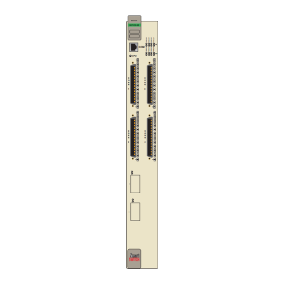
Slots 5 and 6 (interfaces 9 and 10) of the 6H123-50 support optional Fast Ethernet Interface Modules providing uplinks to 100BASE-TX or 100BASE-FX Fast Ethernet networks. The 6H133-37 is capable of being equipped with a High Speed Interface Module (HSIM) that provides for... - Page 18 Chapter 1: Introduction Ethernet 6H123-50 Figure 1-1 The 6H123-50 and 6H133-37 COM Ports Ethernet/Fast Ethernet Interfaces 1 - 8 1 - 6 Fast Ethernet Interface Module Slots (Slots 5 and 6) HSIM Slot 6H123-50 and 6H133-37 User’s Guide Ethernet 6H133-37...
-
Page 19: Connectivity
Fast Ethernet backbones or a high speed connection to a local server. The 6H133-37 has one front panel slot for an optional High Speed Interface Module (Interface 7) to provide for additional connectivity to other high speed networking technologies such as ATM, FDDI, and WANs. -
Page 20: Full Duplex Switched Ethernet
SmartTrunk links. The SmartTrunk benefits are as follows: • All purchased bandwidth is used. • Distributed, resilient links increase reliability and performance. • Multiple technologies are supported within a single trunk for maximum flexibility. 6H123-50 and 6H133-37 User’s Guide... -
Page 21: Management
SecureFast Switching Virtual Network Services between all of the front panel interfaces including Fast Ethernet Interface Modules installed in a 6H123-50 or an HSIM installed in a 6H133-37. IEEE 802.1Q switching and SecureFast switching allow for future migration to Virtual Network technologies without requiring the replacement of existing equipment. -
Page 22: Lanview Diagnostic Leds
When the 6H123-50 and the 6H133-37 are connected to the network and powered up, Runtime IP Address Discovery (RAD) checks the 6H123-50 and the 6H133-37 for an IP address. If one has not yet been assigned (6H123-50 and 6H133-37 IP address set to 0.0.0.0), RAD checks to see if any of the interfaces have a link. -
Page 23: Local Management Features
• Manage any module installed in the 6C105 via a single terminal connection. • Assign an IP address and subnet mask to the 6H123-50, 6H133-37 and 6C105 chassis. • Select a default gateway. • Control local and remote access. - Page 24 Systems for the 6H133-37 to provide additional connectivity to other high speed networking technologies such as Asynchronous Transfer Mode (ATM), Wide Area Networks (WANs) and Fiber Distributed Data Interface (FDDI). The HSIMs available for the 6H133-37 are listed in the Release Notes. 1-10...
-
Page 25: Document Conventions
Caution symbol. Contains information essential to avoid damage to the equipment. CAUTION Electrical Hazard Warning symbol. Warns against an action that could result in personal injury or death due to an electrical hazard. 6H123-50 and 6H133-37 User’s Guide Document Conventions 1-11... -
Page 26: Getting Help
• The device history (i.e., have you returned the device before, is this a recurring problem, etc.) • Any previous Return Material Authorization (RMA) numbers 1-12 http://www.cabletron.com/ (603) 332-9400 support@cabletron.com ftp://ftp.cabletron.com/ anonymous your email address 6H123-50 and 6H133-37 User’s Guide... -
Page 27: Related Manuals
Manager software is contained on the VLAN Manager CD-ROM. Documents for the Cabletron Systems HSIM-W6 and HSIM-W84 devices are contained on the QuickSET CD-ROM and are also available on the World Wide Web at: http://www.cabletron.com/ 6H123-50 and 6H133-37 User’s Guide Related Manuals 1-13... - Page 28 Chapter 1: Introduction 1-14 6H123-50 and 6H133-37 User’s Guide...
-
Page 29: Chapter 2 Network Requirements
Cabletron Systems World Wide Web site: http://www.cabletron.com/ SmartTrunk To connect the 6H123-50 and 6H133-37 to a network so they can take advantage of the SmartTrunk feature, there are certain rules concerning port connections and configurations that must be followed for proper operation. -
Page 30: 100Base-Tx Network
100BASE-TX NETWORK When connecting a 100BASE-T segment to any ports of CONN 1 through CONN 4 (6H123-50), CONN 1 through CONN 3 (6H133-37), or an FE-100TX installed in slot 5 or 6 of the 6H123-50, the device at the other end of the twisted pair segment must meet IEEE 802.3u 100BASE-TX Fast Ethernet network requirements for the devices to operate at 100 Mbps. -
Page 31: Chapter 3 Installation
Only qualified personnel should install the 6H123-50 and 6H133-37. This chapter provides the instructions required to install the 6H123-50 and 6H133-37, Follow the order of the sections listed below to ensure a proper installation: • Required tools (Section • Unpacking the 6H123-50 and 6H133-37 •... -
Page 32: Options
CAUTION or components. The 6H123-50 and 6H133-37 can be installed in any of the 5 slots that are available in the 6C105. To install a module, proceed as follows: Remove the blank panel covering the slot in which the module is to be installed. - Page 33 Installing the 6H123-50 and 6H133-37 into the 6C105 Chassis Remove the module from the plastic bag. (Save the bag in the event the module must be reshipped.) Observe all precautions to prevent damage from Electrostatic Discharge (ESD). Examine the module for damage. If any damage is apparent, DO NOT install the module.
- Page 34 Chapter 3: Installation Slot Number Metal Back-Panel Figure 3-1 Installing an Interface Module Ethernet 6H133-37 Circuit Card Card Guides 6H123-50 and 6H133-37 User’s Guide Plastic Locking Tab Plastic Locking Tab 2276_02...
-
Page 35: Connecting To The Network
fiber optic cable connection. The FE-100F3 has an SC style connector for a single mode fiber optic cable connection. Refer to Section 3.5.1 through 4 and CONN 1 through 3 of the 6H123-50 and 6H133-37. Refer to Section 3.5.2 FE-100TX. Refer to Section 3.5.3... -
Page 36: Connecting Utp Cables
Chapter 3: Installation 3.5.1 Connecting UTP Cables When facing the front panel of the 6H123-50 and 6H133-37, the RJ21 connectors represent Ethernet/Fast Ethernet segments 1 through 8 and segments 1 through 6, respectively. To connect a UTP segment to the 6H123-50 and 6H133-37, proceed as... -
Page 37: Connecting A Twisted Pair Segment To The Fe-100Tx
Fast Ethernet Interface Module crossover switch shown in position, marked with =. 6H123-50 and 6H133-37 User’s Guide Connecting to the Network Chapter for details. - Page 38 Center. Refer to Section 1.6 Figure 3-3 FE-100TX Figure 3-3. Section 2.3. for details. 6H123-50 and 6H133-37 User’s Guide shows how to properly set Position = (not crossed over) 5. NC 1. TX+ 6. RX- 2. TX- 7. NC 3. RX+ 8.
-
Page 39: Connecting A Fiber Optic Segment To The Fe-100Fx And Fe-100F3
Insert one end of the SC connector into the FE-100FX or FE-100F3 installed in the 6H123-50. See At the other end of the fiber optic cable, attach the SC connector to the other device. 6H123-50 and 6H133-37 User’s Guide Connecting to the Network Figure 3-4. - Page 40 Section If a link has not been established, contact the Cabletron Systems Global Call Center. Refer to Section 1.6 The 6H123-50 and 6H133-37 are now ready to be set up through Local Management. Refer to chassis. 3-10 TX LED RX LED 2.4.
-
Page 41: Chapter 4 Troubleshooting
(Section 4.3) • Using the RESET button USING LANVIEW The 6H123-50 and 6H133-37 use Cabletron Systems built-in visual diagnostic and status monitoring system called LANVIEW. The LANVIEW LEDs (Figure status to aid in diagnosing network problems. Refer to description of the LEDs. - Page 42 Chapter 4: Troubleshooting CPU LED Receive (RX) Ethernet 6H133-37 Transmit (TX) Ethernet Interface Status LEDs Fast Ethernet Interface Status LEDs Repeater Port Status LEDs Port Status LEDs 2276_04 Figure 4-1 LANVIEW LEDs 6H123-50 and 6H133-37 User’s Guide Link Status Operating Speed...
- Page 43 Ethernet Receive Status (RX) of Green RJ21 Interfaces Amber 10 Mbps Segment 6H123-50 and 6H133-37 User’s Guide Table 4-1 LANVIEW LEDs State Power off. Blinking. Hardware failure has occurred. Solid. Resetting, normal power up reset. Blinking. Crippled. Solid. Testing. Solid. Functional.
- Page 44 No link. No activity. Port enabled or disabled. Blinking. Port disabled, link. Flashing. Port enabled, link, activity. Diagnostic failure. 6H123-50 and 6H133-37 User’s Guide Recommended Action No action. No action. No action. No action. Contact the Cabletron Systems Global Call Center for assistance.
- Page 45 Status Green Repeater Port Status Operating Green Speed Status 6H123-50 and 6H133-37 User’s Guide State Port enabled, and no activity. Should flash green every 2 seconds indicating BPDUs being sent if STA is enabled and there is a valid link.
-
Page 46: Fe-100Tx Led
Table 4-2 FE-100TX LED Indications When the RX LED Is On Color 10/100 Green provide a functional description of the FE-100TX FE-100TX Figure 4-2 FE-100TX LED Description FE-100TX is operating at 10 Mbps. FE-100TX is operating at 100 Mbps. 6H123-50 and 6H133-37 User’s Guide Figure 4-2. 2276-36... -
Page 47: Troubleshooting Checklist
Table 4-3 FE-100TX LED Indications When the RX LED Is Off Color 10/100 Green TROUBLESHOOTING CHECKLIST If the 6H123-50 and 6H133-37 are not working properly, refer to Table 4-4 for a checklist of possible problems, causes, and recommended actions to resolve the problem. Table 4-4 Troubleshooting Checklist... -
Page 48: Using The Reset Button
Check link to device. 1. Review network design 2. Call the Cabletron 1. Reenter the lost 2. Call the Cabletron 4-3) resets the 6H123-50 and 6H133-37 6H123-50 and 6H133-37 User’s Guide Section 5.16 Section 5.15.1 for IP and delete unnecessary loops. - Page 49 RESET Button 2276-37 Figure 4-3 RESET Button To reset the 6H123-50 and 6H133-37 processor, press and release the RESET button. The 6H123-50 and 6H133-37 go through a reset process of approximately 20 seconds. Additional downtime occurs as the module reenters the network.
- Page 50 Chapter 4: Troubleshooting 4-10 6H123-50 and 6H133-37 User’s Guide...
-
Page 51: Chapter 5 Local Management
Note to alert the reader. OVERVIEW Local Management for the 6H123-50 and 6H133-37 consists of a series of management screens that enable the management of the module, the attached segments and the 6C105 chassis. The management screens enable the user to do the following tasks: •... - Page 52 There are three ways to access Local Management: • Locally using a VT type terminal connected to the COM port of the 6H123-50 and 6H133-37. • Remotely using a VT type terminal connected through a modem. • In-band through a Telnet connection. 6H123-50 and 6H133-37 User’s Guide...
-
Page 53: Local Management Keyboard Conventions
SPACE bar BACKSPACE Key Arrow Keys [–] Key DEL Key 6H123-50 and 6H133-37 User’s Guide Local Management Keyboard Conventions Function These are selection keys that perform the same Local Management function. For example, “Press ENTER” means that you can press either ENTER or RETURN, unless this manual specifically... -
Page 54: Management Terminal Setup
A Digital Equipment Corporation VT100 type terminal • A VT type terminal running emulation programs for the Digital Equipment Corporation VT100 series • A remote VT100 type terminal via a modem connection • In-band via a Telnet connection 6H123-50 and 6H133-37 User’s Guide... -
Page 55: Console Cable Connection
6H123-50 and 6H133-37 as follows: Connect the RJ45 connector at one end of the cable (supplied in the kit) to the COM port on the 6H123-50 and 6H133-37. Plug the RJ45 connector on the other end of the cable into the RJ45-to-DB9 adapter (supplied in the kit). -
Page 56: Management Terminal Setup Parameters
XOFF at 64 8 bits No Parity 1 Stop Bit No Local Echo DEC-423, Data Leads Only Limited Transmit No Auto Answerback Keyboard Setup Menu Typewriter Keys any option any option Margin Bell Warning Bell 6H123-50 and 6H133-37 User’s Guide... -
Page 57: Telnet Connections
Once the module or chassis has a valid IP address, the user can establish a Telnet session with Local Management from any TCP/IP based node on the network. Telnet connections to the 6H123-50 and 6H133-37 require the community name passwords assigned at the SNMP Community Names screen of either the 6C105 chassis or the module. -
Page 58: Monitoring An Uninterruptible Power Supply
Use the Console Cable Kit provided with the 6C105 chassis to attach the UPS to the module COM port as shown in Connect the UPS device to the COM port of the 6H123-50 and 6H133-37 as follows: Connect the RJ45 connector at one end of the cable to the COM port on the 6H123-50 and 6H133-37. - Page 59 RJ45 COM Port DB9 Port UPS Device RJ45-to-DB9 UPS Adapter Figure 5-2 Uninterruptible Power Supply (UPS) 6H123-50 and 6H133-37 User’s Guide Management Terminal Setup Ethernet 6H133-37 UTP Cable With RJ45 Connectors Ethernet 6H133-37 226951...
-
Page 60: Accessing Local Management
Figure 5-3. Whenever a connection is made to the 6H123-50 and 6H133-37 the Password screen displays. Before continuing, the user must enter a password which is compared to the previously stored passwords. The level of access allowed the user depends on the password. To set or change passwords refer to procedure to access Local Management. -
Page 61: Navigating Local Management Screens
The 6H123-50 and 6H133-37 Local Management application consists of a series of menu screens. Navigate through Local Management by selecting items from the menu screens. The 6H123-50 and 6H133-37 support three modes of switch operation. The switching modes are as follows: •... - Page 62 Port Redirect Function General Configuration SNMP Community Names SNMP Traps Switch Configuration Module Specific Configuration Menu Switch Statistics Interface Statistics RMON Statistics Repeater Statistics 6H123-50 and 6H133-37 User’s Guide System Resources Fast High Speed Ethernet Interface HSIM Configuration Flash Download Port Redirect...
-
Page 63: Selecting Local Management Menu Screen Items
Use the arrow keys to highlight the EXIT command at the bottom of the Local Management Screen. Press ENTER. The Password screen displays and the session ends. 6H123-50 and 6H133-37 User’s Guide Accessing Local Management General Configuration SNMP Community Names... - Page 64 ESC twice. This exit method does not warn about unsaved changes and all unsaved changes are lost. Exit from 6H123-50 and 6H133-37 Local Management by repeating steps 1 and 2 until the Main Menu screen displays. Use the arrow keys to highlight the RETURN command at the bottom of the Main Menu screen.
-
Page 65: Main Menu Screen
The Modules menu item provides access to the Module Selection screen that is used to select individual modules in the chassis for management purposes. For details about the Module Selection screen, refer to Section 5.12. 6H123-50 and 6H133-37 User’s Guide 5-15... -
Page 66: Chassis Menu Screen
6C105 chassis. For details, refer to 5-16 Figure 5-8, provides access to Local Section 6C105 LOCAL MANAGEMENT Chassis Menu CHASSIS CONFIGURATION SNMP COMMUNITY NAMES SNMP TRAPS CHASSIS ENVIRONMENTAL PORT REDIRECT FUNCTION 6H123-50 and 6H133-37 User’s Guide 5.6. RETURN 22761_99 Section 5.7. -
Page 67: Snmp Community Names
The Port Redirect Function screen enables the user to redirect traffic from one or multiple modules and ports in the chassis to a specific destination module or port. For details, refer to Section 5.11. 6H123-50 and 6H133-37 User’s Guide 5-17... -
Page 68: Chassis Configuration Screen
6C105 LOCAL MANAGEMENT Chassis Configuration 00-00-ID-00-00-00 Chassis Date: 0.0.0.0 Chassis Time: 255.255.0.0 Screen Refresh Time: Screen Lockout Time: Chassis Uptime XX D XX H XX M EXIT 5.7.2. 6H123-50 and 6H133-37 User’s Guide 10/11/97 14:23:00 30 sec. 15 min. RETURN 2276_98... - Page 69 Contains the rate at which the LM screens are updated. This setting determines how frequently (in seconds) information is updated on the screen. To enter a new update time, refer to 6H123-50 and 6H133-37 User’s Guide Chassis Configuration Screen Section Section 5.7.5.
- Page 70 Operational Mode (Selectable) This field enables the user to set the 6H123-50 and 6H133-37 to operate as an 802.1D switch (Switching option), as a Cabletron Systems SecureFast switch (SFPS VLAN option) or as an 802.1Q switch.
-
Page 71: Setting The Subnet Mask
To set the IP address, perform the following steps: Use the arrow keys to highlight the IP Address field. Enter the IP address into this field using Decimal Dotted Notation (DDN) format. For example: 134.141.79.120 6H123-50 and 6H133-37 User’s Guide Chassis Configuration Screen 5-21... - Page 72 ARE YOU SURE YOU WANT TO CONTINUE? Figure 5-10 Configuration Warning Screen Use the arrow keys to highlight the YES command and press ENTER. The changes are saved and the module reboots. 5-22 Figure 5-10 WARNING! 6H123-50 and 6H133-37 User’s Guide displays. 19601-84...
-
Page 73: Setting The Chassis Date
Management does not alter the current value, but it does refresh the Chassis Date field with the previous value. Upon saving the new chassis date, all interface modules NOTE installed in the chassis recognize the new value as the current date. 6H123-50 and 6H133-37 User’s Guide Chassis Configuration Screen 5-23... -
Page 74: Setting The Chassis Time
Press ENTER to set the refresh time to the time entered in the input field. Use the arrow keys to highlight the SAVE command at the bottom of the screen and press ENTER. 5-24 ., type “064500” in the 6H123-50 and 6H133-37 User’s Guide... -
Page 75: Setting The Screen Lockout Time
Line at the top of the screen displays “SAVED OK”. If the entry is not valid, Local Management does not alter the current setting, but it does refresh the Screen Lockout Time field with the previous value. 6H123-50 and 6H133-37 User’s Guide Chassis Configuration Screen 5-25... -
Page 76: Snmp Community Names Screen
Community Names screen, Event Message Line Community Name public public public SAVE Figure 5-11 SNMP Community Names Screen 5-26 Figure 5-11, displays. 6C105 LOCAL MANAGEMENT SNMP Community Names Access Policy read-only read-write super-user EXIT 6H123-50 and 6H133-37 User’s Guide RETURN 2276_97... - Page 77 Indicates the access accorded each community name. Possible selections are as follows: read-only read-write super-user 6H123-50 and 6H133-37 User’s Guide SNMP Community Names Screen This community name allows read-only access to the 6C105 MIB objects, and excludes access to security-protected fields of read-write or super-user authorization.
-
Page 78: Establishing Community Names
The community names are saved to memory and their access modes implemented. Exiting without saving causes a “NOT SAVED?” message to NOTE display above the SAVE command. Edits are lost if they are not saved before exiting. 5-28 Section 5.16. 6H123-50 and 6H133-37 User’s Guide... -
Page 79: Snmp Traps Screen
Trap Community Name (Modifiable) Displays the Community Name included in the trap message sent to the Network Management Station with the associated IP address. 6H123-50 and 6H133-37 User’s Guide 6C105 LOCAL MANAGEMENT SNMP Traps Trap Community Name... -
Page 80: Configuring The Trap Table
Exiting without saving causes a “NOT SAVED?” message to NOTE appear above the SAVE command. Edits will be lost if they are not saved before exiting. The designated workstations now receive traps from the 6C105. 5-30 6H123-50 and 6H133-37 User’s Guide... -
Page 81: Chassis Environmental Information Screen
Power Supply # X Status (Read-Only) Displays the current status of power supplies 1 and 2 for the 6C105. This field will read either “Normal”, “Fault”, or “Not Installed”. 6H123-50 and 6H133-37 User’s Guide Chassis Environmental Information Screen Figure 5-13, displays. -
Page 82: Port Redirect Function Screen
Access the Port Redirect Function screen from the Chassis Menu screen by using the arrow keys to highlight the PORT REDIRECT FUNCTION menu item and pressing ENTER. The Port Redirect Function screen, Figure 5-32 Figure 5-14, enables the user to set 5-14, displays. 6H123-50 and 6H133-37 User’s Guide... - Page 83 (ON), or to drop all errored frames before forwarding traffic (OFF). 6H123-50 and 6H133-37 User’s Guide Port Redirect Function Screen 6C105 LOCAL MANAGEMENT Port Redirect Function...
-
Page 84: Displaying The Source And Destination Entries
To display the next screen, use the arrow keys to highlight NEXT. Press ENTER and the next screen of entries displays. To display the previous screen, use the arrow keys to highlight PREVIOUS. Press ENTER to view the entries in the previous screen. 5-34 6H123-50 and 6H133-37 User’s Guide... -
Page 85: Changing Source And Destination Ports
If more than one port is to be redirected, repeat steps 1 through NOTE 6 for each additional setting, then go to step 7 to save all the new settings at once. 6H123-50 and 6H133-37 User’s Guide Port Redirect Function Screen 5-35... -
Page 86: Module Selection Screen
Event Message Line Slot # <5> Figure 5-15 Module Selection Screen 5-36 6C105 LOCAL MANAGEMENT Module Selection Module Type Serial # 6H133-37 123456789 6H123-50 123456789 6H133-37 123456789 6H123-50 123456789 6H123-50 123456789 EXIT 6H123-50 and 6H133-37 User’s Guide Hardware Revision RETURN 2276-39... -
Page 87: Selecting A Module
To select an individual module to perform Local Management functions, proceed as follows: Use the arrow keys to highlight the desired module number in the Slot # field. Press ENTER, the applicable Module Menu screen displays. 6H123-50 and 6H133-37 User’s Guide Module Selection Screen 5-37... -
Page 88: Module Menu Screen
MODULE MENU SCREEN The Local Management screens shown in this chapter are for NOTE the 6H123-50. The 6H133-37 shares most of the following Local Management screens. All Local Management functions specific to any one interface module are preceded by a Note to alert the reader. -
Page 89: Module Configuration
Section 5.30. NETWORK TOOLS Accesses the Network Tools, which resides on the 6H123-50 and 6H133-37 and consists of a series of commands that enable the user to access and manage network devices. Section 5.35 explains how to use the Network Tools utility. -
Page 90: Module Configuration Menu Screen
The Module Configuration Menu screen, Local Management screens that enable you to configure and monitor operating parameters, modify SNMP community names, set SNMP traps, configure switch parameters and configure the 6H123-50 and 6H133-37 ports. The following menu items on the Module Configuration Menu... - Page 91 The following briefly defines each screen accessible from the Module Configuration Menu screen: GENERAL CONFIGURATION The General Configuration screen enables the user to monitor and configure operating parameters for the 6H123-50 and 6H133-37. For details, refer to Section 5.15. SNMP COMMUNITY NAMES...
-
Page 92: General Configuration Screen
6H123-50 LOCAL MANAGEMENT General Configuration 00-00-ID-00-00-00 0.0.0.0 255.255.0.0 NONE DEFINED 0.0.0.0 Management Mode: [Distributed] [LM] EXIT 6H123-50 and 6H133-37 User’s Guide Firmware Revision: XX.XX.XX BOOTPROM Revision: XX.XX.XX Module Date: 10/11/1997 Module Time: 14:23:00 Screen Refresh Time: 30 sec. Screen Lockout Time: 15 min. - Page 93 Section 5.15.3. TFTP Gateway IP Addr (Modifiable) Displays and enables the user to set the TFTP Gateway IP address for the 6H123-50 and 6H133-37. To set the TFTP Gateway IP address, refer to Section 5.15.4. Module Date (Modifiable) Contains a value that the module recognizes as the current date. To set a...
- Page 94 Displays the total time that the module has been operating. Operational Mode (Selectable) Used to set the 6H123-50 or 6H133-37 so it operates as an 802.1D switch (802.1D SWITCHING), an IEEE 802.1Q switch (802.1Q SWITCHING), or as a Cabletron Systems SecureFast switch (SECURE FAST VLAN).
-
Page 95: Setting The Ip Address
IP Fragmentation (Toggle) This field enables the user to enable or disable IP Fragmentation. The default setting for this field is ENABLED. If the 6H123-50 and 6H133-37 will be bridged to an FDDI ring, IP Fragmentation must be enabled. If IP Fragmentation is disabled, all FDDI frames that exceed the maximum Ethernet frame size will be discarded. - Page 96 Use the arrow keys to highlight the YES command and press ENTER. The changes are saved and the module resets. The module automatically resets after a new IP address is NOTE saved. 5-46 WARNING! 6H123-50 and 6H133-37 User’s Guide Figure 5-19, displays. 19601-84...
-
Page 97: Setting The Subnet Mask
5.15.2 Setting the Subnet Mask If the management workstation that is to receive SNMP traps from the 6H123-50 and 6H133-37 is located on a separate subnet, the subnet mask for the 6H123-50 and 6H133-37 must be changed from its default. -
Page 98: Setting The Default Gateway
5.15.4 Setting the TFTP Gateway IP Address If the network TFTP server is located on a different IP subnet than the 6H123-50 and 6H133-37, a Gateway IP address should be set. To set the TFTP Gateway IP address, perform the following steps: Use the arrow keys to highlight the TFTP Gateway IP Addr field. -
Page 99: Setting The Module Date
If the 6C105 chassis has been assigned a chassis date, it is not NOTE necessary to assign a module date to the 6H123-50 and 6H133-37. All installed modules recognize the chassis date of the 6C105. Use the arrow keys to highlight the Module Date field. -
Page 100: Setting The Module Time
If the 6C105 chassis has been assigned a chassis time, it is not NOTE necessary to assign a module time to the 6H123-50 and 6H133-37. All installed modules recognize the chassis time of the 6C105. Use the arrow keys to highlight the Module Time field. -
Page 101: Setting The Screen Lockout Time
Line at the top of the screen displays “SAVED OK”. If the entry is not valid, Local Management does not alter the current setting, but it does refresh the Screen Lockout Time field with the previous value. 6H123-50 and 6H133-37 User’s Guide General Configuration Screen 5-51... -
Page 102: Setting The Operational Mode
ENTER. The Configuration Warning screen shown back in Figure 5-19 If the 6H123-50 and 6H133-37 have been set to SecureFast NOTE VLAN, refer to your SecureFast documentation set to configure the devices for this type of operation. -
Page 103: Setting The Management Mode
The changes are saved and the module reboots. Upon saving the new operational mode, the module reboots. NOTE If the 6H123-50 and 6H133-37 have been set to 802.1Q SWITCHING, refer to the Port Based VLAN User’s Guide to configure the devices for this type of operation. -
Page 104: Configuring The Com Port
(Refer to CAUTION Section 5.15.1.) Read this entire COM port configuration section before changing the settings of the COM port. The 6H123-50 and 6H133-37 COM ports support the following applications: • Local Management connections •... - Page 105 OK” displays, the edits are saved. Exiting without saving causes the message “NOT SAVED -- PRESS SAVE TO KEEP CHANGES” to appear. Exiting without saving causes all edits to be lost. CAUTION 6H123-50 and 6H133-37 User’s Guide General Configuration Screen WARNING Section 5.15.11.1. If you...
-
Page 106: Changing The Com Port Application
When the message “SAVED OK” appears, the edits made are saved. 5-56 Application Local Management Session APC Power Supply SNMP Proxy for instructions on clearing NVRAM in order to 6H123-50 and 6H133-37 User’s Guide Section 5.15.11, you can Table 5-3 lists the... -
Page 107: Clearing Nvram
Figure 5-21 Clear NVRAM Warning Screen Use the arrow keys to highlight YES and press ENTER. The message “CLEARING NVRAM. REBOOT IN PROGRESS...” displays. The 6H123-50 and 6H133-37 clear NVRAM and reboot. All user-entered parameters default to factory settings. 6H123-50 and 6H133-37 User’s Guide General Configuration Screen... -
Page 108: Enabling/Disabling Ip Fragmentation
Chapter 5: Local Management 5.15.13 Enabling/Disabling IP Fragmentation If the 6H133-37 is being bridged to an FDDI ring (for example, via an HSIM-F6 installed in the 6H133-37) IP Fragmentation CAUTION should be enabled. If IP Fragmentation is disabled, all FDDI frames that exceed the maximum Ethernet frame size will be discarded. - Page 109 The following defines each SNMP Community Names screen field: Community Name (Modifiable) Displays the user-defined name through which a user accesses 6H123-50 and 6H133-37 management. Any community name assigned here acts as a password to Local/Remote Management. 6H123-50 and 6H133-37 User’s Guide...
-
Page 110: Establishing Community Names
Enter the password in the field (maximum 31 characters). Press ENTER. 5-60 This community name allows read-only access to the 6H123-50 and 6H133-37 MIB objects, and excludes access to security-protected fields of read-write or super-user authorization. This community name allows read and write access to the 6H123-50 and 6H133-37 MIB objects, excluding security protected fields for... - Page 111 Exiting without saving causes a “NOT SAVED?” message to NOTE display. Edits are lost if they are not saved before exiting. To exit the screen, use the arrow keys to highlight RETURN and press ENTER. 6H123-50 and 6H133-37 User’s Guide SNMP Community Names Screen 5-61...
-
Page 112: Snmp Traps Screen
Chapter 5: Local Management 5.17 SNMP TRAPS SCREEN Since the 6H123-50 and 6H133-37 are SNMP compliant devices, they can send messages to multiple Network Management Stations to alert users of status changes. The SNMP Traps screen is shown in It is only necessary to assign SNMP traps if the user desires... -
Page 113: Configuring The Trap Table
SAVE command. Edits are lost if they are not saved before exiting. To exit the screen, use the arrow keys to highlight RETURN and press ENTER. The designated workstations now receive traps from the 6H123-50 and 6H133-37. 6H123-50 and 6H133-37 User’s Guide SNMP Traps Screen 5-63... -
Page 114: Switch Configuration Screen
FAST VLAN. This screen may only be used by modules configured to operate as 802.1D or 802.1Q switches. Depending on the optional interfaces installed and if the device is a 6H123-50 or 6H133-37, there can be 10 or 7 switched or network ports. Table 5-4 shows the CONN/port organization. - Page 115 (Root) switch when two or more switches exist in parallel (Spanning Tree Algorithm). Valid entries include IEEE, DEC, and NONE. To set the STA, refer to 6H123-50 and 6H133-37 User’s Guide Switch Configuration Screen 6H133-37 CONN 1 = Network Port 1, 10 Mbps...
- Page 116 Age Time (Modifiable) Enables the user to set the amount of time (in seconds) the 6H123-50 and 6H133-37 keep an address in its switch table before discarding it. The modules will discard an address from their switch table if they do not receive a valid frame from the applicable address in the amount of time specified in the Age Time field.
-
Page 117: Setting The Sta
Time range is 10 to 1,000,000 seconds with the default value being 300 seconds. Use the arrow keys to highlight the SAVE command at the bottom of the screen. Press ENTER. The message “SAVED OK” displays. 6H123-50 and 6H133-37 User’s Guide Switch Configuration Screen 5-67... -
Page 118: Setting (Enabling Or Disabling) The Port Status
Access the Module Specific Configuration screen from the Module Configuration Menu screen by using the arrow keys to highlight the MODULE SPECIFIC CONFIGURATION menu item and pressing ENTER. The Module Specific Configuration screen displays. 5-68 Figure 5-25, enables the user 6H123-50 and 6H133-37 User’s Guide... -
Page 119: System Resources
Auto-Negotiation and Advertised Ability features to be enabled or disabled. For details, refer to The High Speed Interface Configuration screen for the 6H133-37 enables management of an installed HSIM. For details, refer to the applicable HSIM user’s guide. -
Page 120: System Resources Screen
The System Resources screen, Figure 5-26, provides information concerning the processor used in the 6H123-50 and 6H133-37 and the amount of FLASH memory, DRAM, and NVRAM that are installed and how much of that memory is available. Access the System Resources screen from the Module Specific Configuration Menu screen by using the arrow keys to highlight the... - Page 121 Indicates the amount of FLASH memory installed in the 6H123-50 and 6H133-37 and how much is currently available. DRAM Installed (Read-Only) Indicates the amount of DRAM installed in the 6H123-50 and 6H133-37 and how much of it is currently available. NVRAM Installed (Read-Only) Indicates the amount of NVRAM installed in the 6H123-50 and 6H133-37 and how much of it is currently available.
-
Page 122: Setting The Reset Peak Utilization
SCREEN (6H123-50 ONLY) When the HIGH SPEED CONFIGURATION MENU item is NOTE selected for the 6H133-37, the applicable HSIM Setup screen displays. Refer to the HSIM user’s guide to set operating parameters for the HSIM installed in the 6H133-37. To access the High Speed Interface Configuration Menu screen from the Device Specific Configuration Menu screen, use the arrow keys to... - Page 123 Displays the type of interface (FE-100FX, FE-100TX, FE-100F3, or Unknown) installed in slots 5 and 6. FE-100TX interface installed in slot 5 and no interface (indicated by Unknown) in slot 6. 6H123-50 and 6H133-37 User’s Guide 2H23-50R LOCAL MANAGEMENT High Speed Interface Configuration Firmware Revision: BOOTPROM Revision: XX.XX.XX...
- Page 124 (full duplex). In normal operation, the port with an FE-100TX installed is capable of auto-negotiating the operational mode and no further user setup is required. Section 5.21.2 FE-100TX. 5-74 describes how to configure a port with an describes how to manually configure an 6H123-50 and 6H133-37 User’s Guide...
-
Page 125: Configuring An Fe-100Fx Or Fe-100F3
Press ENTER. The port now operates in the chosen mode. Use the arrow keys to highlight the SAVE command. Press ENTER. The message “SAVED OK” displays and Local Management saves the changes to memory. 6H123-50 and 6H133-37 User’s Guide Section 5.21.2.2 Section 5.21.1.1 provides instructions for... -
Page 126: Configuring An Fe-100Tx
100Base-TX, and 100Base-TXFD (full duplex). To set the advertised ability, proceed as follows: Use the arrow keys to highlight the Desired Oper. Mode field. Use the SPACE bar to select the desired mode. 5-76 Section 5.21.2.1 6H123-50 and 6H133-37 User’s Guide... -
Page 127: Flash Download Screen
Before downloading a new image to the module, load the image onto the network TFTP server. For information on how to setup a workstation as a TFTP NOTE server, refer to the specific workstation documentation. 6H123-50 and 6H133-37 User’s Guide Flash Download Screen Figure 5-28, enables the user to Section C.2, for... - Page 128 BOOTP, the module sends out a BootP request to determine the IP address of the TFTP server and the filename of the image to be downloaded. If set for TFTP or RUNTIME, the 6H123-50 and 6H133-37 attempt a TFTP download based on the IP address and filename entered in the fields at the bottom of the Flash Download screen.
- Page 129 BootP. Reboot After Download (Modifiable when user chooses RUNTIME) This field notifies the user that the 6H123-50 and 6H133-37 will reboot after the download is complete. If a RUNTIME Download is performed this field toggles between YES and NO. If YES is selected, the module reboots after the download is completed.
-
Page 130: Image File Download Using Tftp
Chapter 5: Local Management 5.22.1 Image File Download Using TFTP Set the 6H123-50 and 6H133-37 to download to FLASH using TFTP as follows: Use the arrow keys to highlight the Download Method field. Use the SPACE bar to select TFTP. -
Page 131: Image File Download Using Bootp
FLASH memory. 5.22.3 Image File Download Using BootP Set the 6H123-50 and 6H133-37 to download to FLASH using BootP as follows: Use the arrow keys to highlight the Download Method field. -
Page 132: Port Redirect Function Screen
PORT REDIRECT FUNCTION SCREEN The Port Redirect Function screen, each one of the ports on the 6H123-50 and 6H133-37 as a source or destination port. Any port can be set to have one or more destination ports. For example, port 1 can be set as a source port with three destinations, ports 2, 3, and 4. - Page 133 (OFF) to drop all errored frames and only forward traffic without errored frames to the destination ports. 6H123-50 and 6H133-37 User’s Guide Port Redirect Function Screen 6H123-50 LOCAL MANAGEMENT Port Redirect Function Firmware Revision: BOOTPROM Revision: XX.XX.XX...
-
Page 134: Displaying The Source And Destination Entries
To display the next screen, use the arrow keys to highlight NEXT. Press ENTER and the next screen of entries displays. To display the previous screen, use the arrow keys to highlight PREVIOUS. Press ENTER to view the entries in the previous screen. 5-84 6H123-50 and 6H133-37 User’s Guide... -
Page 135: Changing Source And Destination Ports
Use the arrow keys to highlight SAVE at the bottom of the screen. Press ENTER. The message “SAVED OK” displays. This saves the new settings and updates the Source Port and Destination Port read-only fields. 6H123-50 and 6H133-37 User’s Guide Port Redirect Function Screen 5-85... -
Page 136: Broadcast Suppression Screen
999:23:59 150000 999:23:59 150000 999:23:59 150000 999:23:59 150000 999:23:59 150000 999:23:59 150000 999:23:59 150000 999:23:59 EXIT 6H123-50 and 6H133-37 User’s Guide Firmware Revision: XX.XX.XX BOOTPROM Revision: XX.XX.XX Threshold Reset Peak 150000 [NO] 150000 [NO] 150000 [NO] 150000 [NO] 150000 [NO]... - Page 137 Reset Peak (Toggle) Enables the user to reset the peak rate. Resetting the Peak Rate also resets the Time Since Peak field. The Reset Peak field toggles between YES and 6H123-50 and 6H133-37 User’s Guide Broadcast Suppression Screen Table 5-6...
-
Page 138: Setting The Threshold
Use the arrow keys to highlight the Reset Peak field for the selected port. Press the SPACE bar to select YES or NO. Use the arrows keys to highlight the SAVE command at the bottom of the screen. Press ENTER. The message “SAVED OK” displays. 5-88 6H123-50 and 6H133-37 User’s Guide... -
Page 139: Vlan Main Menu (802.1Q) Screen
SECURE FAST VLAN. This screen is only used by devices configured to operate as an 802.1Q switch. Refer to the Cabletron Systems Port Based VLAN User’s Guide for information on 802.1Q VLAN. 6H123-50 and 6H133-37 User’s Guide VLAN Main Menu (802.1Q) Screen 6C105 LOCAL MANAGEMENT VLAN Main Menu... -
Page 140: Repeater Configuration Menu Screen
5-90 Figure 6H123-50 LOCAL MANAGEMENT Repeater Configuration Menu REPEATER PORT CONFIGURATION MODULE LEVEL SECURITY CONFIGURATION PORT LEVEL SECURITY CONFIGURATION EXIT Section 6H123-50 and 6H133-37 User’s Guide 5-32, is used to access Firmware Revision: XX.XX.XX BOOTPROM Revision: XX.XX.XX RETURN 5.27. 2745_104... - Page 141 (LockedOnAddr). For details, refer to Section 5.28. PORT LEVEL SECURITY CONFIGURATION Used to set the security for all ports of a connector. For details, refer to Section 5.29. 6H123-50 and 6H133-37 User’s Guide Repeater Configuration Menu Screen 5-91...
-
Page 142: Repeater Port Configuration Screen
Unknown [Auto-Neg] Unknown [Auto-Neg] Unknown [Auto-Neg] Unknown [Auto-Neg] CONNECTOR #: [1] for the connector (CONN)/repeater port 6H123-50 and 6H133-37 User’s Guide 5-33, is used to monitor Firmware Revision: XX.XX.XX BOOTPROM Revision: XX.XX.XX MODE PORT STAT [Disabled] [Enabled] [Enabled] [Enabled] [Enabled]... - Page 143 Displays the Link status (Link or No Link) of the port. CURRENT OPER. (Read-only) Displays the current operating mode of the port. 6H123-50 and 6H133-37 User’s Guide Repeater Port Configuration Screen 2H33-37R or 6H133-37 CONN 1 = Repeater ports 1 – 12 CONN 2 = Repeater ports 13 –...
-
Page 144: Setting The Port Operating Mode
Use the SPACE bar to step to the appropriate Operating Mode (Auto-Neg, 10Base-T, or 100Base-TX). If setting the operating mode on other ports, repeat steps 3 and 4 for each one and then proceed to step 6. 5-94 Section Section 5.27.2. Section 5.27.3. 6H123-50 and 6H133-37 User’s Guide 5.27.1. -
Page 145: Enabling /Disabling Ports
(Auto-Neg, 10Base-T, or 100Base-TX). Use the arrow keys to highlight the SAVE command. Press ENTER. The message “SAVED OK” displays and all networks of the connector are set to the selected operating mode. 6H123-50 and 6H133-37 User’s Guide Repeater Port Configuration Screen 5-95... -
Page 146: Enabling/Disabling Network Ports
To access the Module Level Security Configuration screen, use the arrow keys to highlight the MODULE LEVEL SECURITY CONFIGURATION menu item on the Repeater Configuration Menu screen and press ENTER. The Module Level Security Configuration screen displays. 5-96 Figure 6H123-50 and 6H133-37 User’s Guide 5-34, is used to... - Page 147 CONN 2 = Repeater ports 13 – 24 CONN 3 = Repeater ports 25 – 36 CONN 4 = Repeater ports 37 – 48 6H123-50 and 6H133-37 User’s Guide Module Level Security Configuration 6H123-50 LOCAL MANAGEMENT Module Level Security Configuration Firmware Revision: BOOTPROM Revision: XX.XX.XX...
- Page 148 With NoDisable set, the port is not turned off. • SendTrap/NoTrap – SendTrap causes the switch to send an SNMP trap when a port detects a security violation. With NoTrap set, no SNMP trap is sent. 5-98 6H123-50 and 6H133-37 User’s Guide...
-
Page 149: Setting The Module Level Security
Use the arrow keys to highlight the SAVE command. Press ENTER. The message “SAVED OK” displays and all ports of the connector are set to the selected operating mode. 6H123-50 and 6H133-37 User’s Guide Module Level Security Configuration 5-99... -
Page 150: Port Level Security Configuration Screen
Figure 5-35 Port Level Security Configuration Screen 5-100 Figure 6H123-50 LOCAL MANAGEMENT Port Level Security Configuration Firmware Revision: BOOTPROM Revision: XX.XX.XX Action On Intruder [DisablePort] [SendTrap] 6H123-50 and 6H133-37 User’s Guide 5-35, functions XX.XX.XX Address [00-00-00-00-00-00] [xx.xx.xx.xx.xx.xx] [00-00-00-00-00-00] [00-00-00-00-00-00] [00-00-00-00-00-00]... - Page 151 CONN 3 = Network 5, 10 Mbps Network 6, 100 Mbps CONN 3 = Network 7, 10 Mbps Network 8, 100 Mbps 6H123-50 and 6H133-37 User’s Guide Port Level Security Configuration Screen Table 5-10 for the connector/repeater port 2H33-37R or 6H133-37 CONN 1 = Repeater ports 1 –...
- Page 152 With NoDisable set, the port is not turned off. • SendTrap/NoTrap – SendTrap causes the switch to send an SNMP trap when a port detects a security violation. With NoTrap set, no SNMP trap is sent. 5-102 6H123-50 and 6H133-37 User’s Guide...
-
Page 153: Setting The Port Level Security
If the security state selected is LockedOnAddr, use the arrow keys to highlight the Address field for the port. Otherwise go to step 11. Enter the address to lock on. 6H123-50 and 6H133-37 User’s Guide Port Level Security Configuration Screen 5-103... -
Page 154: Module Statistics Menu Screen
Access the Module Statistics Menu screen from the Module Menu screen by using the arrow keys to highlight the MODULE STATISTICS menu item and pressing ENTER. The Module Statistics Menu screen displays. 5-104 Figure 5-36, provides access to provides instructions on setting the operational 6H123-50 and 6H133-37 User’s Guide... -
Page 155: Switch Statistics
For details, refer to Section 5.32. RMON STATISTICS The RMON Statistics screen displays all the statistics gathered by the embedded RMON agent built-in to the 6H123-50 and 6H133-37. For details, refer to Section 6H123-50 and 6H133-37 User’s Guide Module Statistics Menu Screen... -
Page 156: Repeater Statistics
The Repeater Statistics screen provides the operating statistics for each port and its corresponding network (Network 1–8 for the 6H123-50 and Network 1–6 for the 6H133-37). This screen also displays the statistics for each repeater port.For details, refer to 5.31... - Page 157 The Switch Statistics screen displays the following fields: Port # (Read-Only) Identifies the port. There can be ten or seven ports depending on if the device is a 6H123-50 or 6H133-37, respectively. port organization. Table 5-12 CONN/Port Organization 6H123-50 CONN 1 = Network Port 1, 10 Mbps...
-
Page 158: Interface Statistics Screen
5.32 INTERFACE STATISTICS SCREEN The Interface Statistics screen is used to gather MIB-II statistics for all of the 6H123-50 and 6H133-37 interfaces (Fast Ethernet Interface Modules and all backplane interfaces) with the exception of an HSIM installed in the 6H133-37. - Page 159 InUnknownProtos (Read-only) The InUnknownProtos field displays the total number of frames that were discarded because the frames were in an unknown, or unsupported, format. 6H123-50 and 6H133-37 User’s Guide 5-109...
- Page 160 “Testing”, no packets will be transmitted or received on this interface. Oper Status (Read-only) This field displays the current status of the interface. If this field displays “Testing”, no packets will be transmitted or received on this interface. 5-110 6H123-50 and 6H133-37 User’s Guide...
-
Page 161: Displaying Interface Statistics
Press the SPACE bar to increment (or press the DEL [delete] key to decrement) the interface number. Press ENTER (neither the Interface # fields nor the statistics change until ENTER is pressed). 6H123-50 and 6H133-37 User’s Guide Interface Statistics Screen Section 5.32.2. -
Page 162: Using The Clear Counters Command
BOOTPROM Revision: XX.XX.XX Owner: monitor Status: valid Total Packets: Total Octets: 64 Octets: 127 Octets: - 255 Octets: - 511 Octets: - 1023 Octets: 1024 - 1518 Octets: CLEAR COUNTERS EXIT 6H123-50 and 6H133-37 User’s Guide Figure 5-39. XX.XX.XX RETURN 2269_65... - Page 163 RMON Index (Read-only) This field displays the current interface for which statistics are being shown. The 6H123-50 and 6H133-37 have an embedded RMON agent that gathers statistics for each interface on the module. Data Source (Read-only) This field displays the source of the statistics data that is currently being displayed on the screen.
- Page 164 CRC. Oversized Pkts (Read-only) The Oversized Packets field displays the number of frames received whose size exceeded 1518 data bytes, not including preamble, but having a valid CRC. 5-114 6H123-50 and 6H133-37 User’s Guide...
- Page 165 128 - 255 Octets (Read-only) Displays the total number of frames, including bad frames, received that were between 128 and 255 bytes in length (excluding framing bits, but including FCS bytes). 6H123-50 and 6H133-37 User’s Guide RMON Statistics Screen 5-115...
-
Page 166: Displaying Rmon Statistics
To reset all the statistics counters of the selected interface to zero, perform the following steps: Use the arrow keys to highlight the CLEAR COUNTERS command. Press ENTER, the counters for the selected index are reset to zero. 5-116 Section Section 5.33.2. 6H123-50 and 6H133-37 User’s Guide 5.33.1. -
Page 167: Repeater Statistics Screen
Network (Read-Only) Indicates the current network port (1 through 8, 6H123-50 or 1 through 6, 6H133-37) for which statistics are displayed. This field is automatically set by selecting a port number in the PORT # command field at the bottom of the screen. - Page 168 Chapter 5: Local Management Table 5-14 shows the association between the CONN and Network Ports for the 6H123-50 and 6H133-37. Table 5-14 CONN/Port Organization 6H123-50 CONN 1 = Network Port 1, 10 Mbps Network Port 2, 100 Mbps CONN 2 = Network Port 3, 10 Mbps...
- Page 169 Displays the number of broadcasts transmitted and received. Multicasts (Read-only) Displays the number of multicasts transmitted and received. Link Status (Read-only) Indicates if the network or port is linked (Link) or not linked (No Link). 6H123-50 and 6H133-37 User’s Guide 5-119...
-
Page 170: Displaying Network Statistics
Press the SPACE bar to increment or press the BACKSPACE key to decrement the port number. Press ENTER (the PORT #, the NETWORK #, and the statistics do not change until ENTER is pressed). 5-120 Section 5.34.2. Section 5.34.3. 6H123-50 and 6H133-37 User’s Guide Section 5.34.1. -
Page 171: Using The Clear Counters Command
SPECIAL: done, quit, or exit - Exit from the Network Tools. For help with a specific command, type 'help <command>'. -> Figure 5-41 Network Tools Screen 6H123-50 and 6H133-37 User’s Guide shows the Network Tools help screen. defroute reset link_trap... - Page 172 Briefly describes the command and its uses. Lists any additional fields in the appropriate format which may be added to the command. Shows an example of the command. 6H123-50 and 6H133-37 User’s Guide...
-
Page 173: Built-In Commands
Description: You can specify the arp command without options, or with one of the following options: Options: 6H123-50 and 6H133-37 User’s Guide arp <options> The arp command provides access to the ARP (Address Resolution Protocol) cache, enabling you to view cache data, delete entries, or add a static route. - Page 174 Specifying a single interface number will affect the bridging status of that interface, while specifying ALL will affect every interface. Not Applicable 6H123-50 and 6H133-37 User’s Guide Media Type 3(dynamic) 3(dynamic) 3(dynamic)
- Page 175 Syntax: Description: Options: Example: -> defroute 2 147.152.42.32 6H123-50 and 6H133-37 User’s Guide defroute defroute [interface number] [IP address] defroute delete [interface number] [IP address] The defroute command allows the user, in the syntax order shown above, to view, set, or delete the default IP route to a managed device through the specified interface.
- Page 176 The ping command generates an outbound ping request to check the status (alive/not alive) of a device at a specified IP address. Not Applicable 6H123-50 and 6H133-37 User’s Guide Oper MAC Addr 0x00 0x00 0x1d 0x07 0x50 0x0e 0x00 0x00 0x1d 0x07 0x50 0x0f...
- Page 177 The Network Tools connection to the device will be terminated upon execution of this command. Options: Example: -> reset 6H123-50 and 6H133-37 User’s Guide reset This reset command initiates a hardware reset of the device.The reset command initializes the CPU processor, runs the onboard diagnostics, and restarts the software image, which restores the user configuration settings from NVRAM.
- Page 178 If the device is not reached, the command displays all next-hop routers to the point of failure. 6H123-50 and 6H133-37 User’s Guide Framing ethernet ethernet...
- Page 179 The Network Tools connection to the device will be terminated upon execution of this command. Options: Example: -> soft_reset 6H123-50 and 6H133-37 User’s Guide Not Applicable soft-reset This command restarts the software image, which restores the user configuration settings from NVRAM. The user will be queried to confirm the reset command to ensure against...
- Page 180 “all” or no ports. When one or all ports are specified to enable, disable, or find their status, their current condition is displayed. Not Applicable 6H123-50 and 6H133-37 User’s Guide 2251-77...
- Page 181 Spanning Tree Algorithm on all ATM interfaces. Syntax: Description: Options: Example: 6H123-50 and 6H133-37 User’s Guide Port 2 is DISABLED Port 4 is ENABLED atm_stp_state [STATE] The atm_stp_state command allows the user to enable, disable, or check the status of the Spanning Tree Algorithm on all ATM interfaces.
-
Page 182: Special Commands
Options: Example: -> done Connection closed 5-132 done, quit, or exit The done, quit, or exit command enables the user to exit from Network Tools and return to the Main Menu screen. Not Applicable 6H123-50 and 6H133-37 User’s Guide 05141-72... -
Page 183: A.3 Environmental Requirements
This appendix provides operating specifications for the Cabletron Systems 6H123-50 and 6H133-37 Interface Modules. Cabletron Systems reserves the right to change these specifications at any time without notice. DEVICE SPECIFICATIONS Processor: Dynamic Random Access Memory (DRAM): FLASH Memory: PHYSICAL PROPERTIES... -
Page 184: Input/Output Ports
Slots accept three types of optional Fast Ethernet Interface Modules: the FE100-TX, FE100-FX and the FE-100F3. Ethernet (10BASE-T/100BASE-TX compliant) with RJ21 type connectors. Slot accepts optional High Speed Interface Module (HSIM). Input/Output Output Output Input Input Output Input 6H123-50 and 6H133-37 User’s Guide... -
Page 185: A.6 Regulatory Compliance
REGULATORY COMPLIANCE This equipment meets the following safety and electromagnetic compatibility (EMC) requirements: Safety 6H123-50 and 6H133-37 User’s Guide Regulatory Compliance UL 1950, CSA C22.2 No. 950, EN 60950, IEC 950, and 73/23/EEC. FCC Part 15, EN 55022, CSA C108.8, EN 50082-1, AS/NZS 3548, VCCI V-3, and 89/336/EEC. - Page 186 Appendix A: Specifications 6H123-50 and 6H133-37 User’s Guide...
-
Page 187: B.1 Fe-100Tx
FE-100TX, FE-100FX AND FE-100F3 The 6H123-50 and the 6H133-37 support three Fast Ethernet Interface Modules: • FE-100TX • FE-100FX • FE-100F3 This appendix provides the specifications for these modules. FE-100TX The FE-100TX uses an RJ45 connector supporting Category 5 Unshielded Twisted Pair (UTP) cabling. -
Page 188: B.2 Fe-100Fx
Figure B-2 uses an SC style connector that Figure B-2 FE-100FX Table B-1 Transmitter Power Worst Case Budget 6.0 dB 9.0 dB 15.0 dB 6H123-50 and 6H133-37 User’s Guide 2276-105 Typical Budget 9.0 dB 12.0 dB 18.0 dB... -
Page 189: B.3 Fe-100F3
If power levels are being measured with an average power meter, add 3 dB to the measurement to compare the measured values to the values listed above. 6H123-50 and 6H133-37 User’s Guide Figure B-3 uses an SC style connector that below. - Page 190 Appendix B: FE-100TX, FE-100FX and FE-100F3 Specifications 6H123-50 and 6H133-37 User’s Guide...
-
Page 191: Optional Installations And Mode Switch Bank Settings
Force download a new image file from a BootP server. • Clear NVRAM and restore all user-entered parameters such as the IP address and subnet mask to the 6H123-50 and 6H133-37 “Default” configuration settings. • Clear user-entered passwords stored in NVRAM and restore the default passwords. - Page 192 Switch 6 – Forced BootP. Changing the position of this switch (i.e., moving the switch from one position to the other) clears download information from NVRAM and forces the 6H123-50 and 6H133-37 to download a new image file from a BootP server after power to the chassis is restored or the reset button is pressed.
- Page 193 RESET button on the front panel is pressed. When the RESET button is pressed, the 6H123-50 and 6H133-37 continue trying to contact a BootP server, but will time out in approximately one minute. If the module times out, the image is downloaded from its FLASH memory.
-
Page 194: C.3 Installing Optional Fast Ethernet Interface Modules
Figure C-2 shows the location of the Fast Ethernet Interface Module connectors on the 6H123-50 boards for slots 5 and 6. For instructions on installing a High Speed Interface Module NOTE (HSIM) in the 6H133-37 refer to the applicable HSIM documentation. Optional Fast Ethernet Interface... - Page 195 Interface Module will be installed. When installing Fast Ethernet Interface Modules in both slots 5 and 6, remove the coverplates from both slot openings. In the following instructions, the optional module is shown being installed in port slot 6. 6H123-50 and 6H133-37 User’s Guide...
- Page 196 Figure C-4. Gently pull the faceplate of the host module forward to allow room for the Fast Ethernet Interface Modules to be aligned over the connector. Figure C-3 6H123-50 and 6H133-37 User’s Guide and proceed as follows: Rear Standoff Front...
- Page 197 Ensure that the Fast Ethernet Interface Module seats flush on the standoffs. Secure the Fast Ethernet Interface Module with the screws saved in steps 1 and 2. 6H123-50 and 6H133-37 User’s Guide Module Module Connector...
- Page 198 Appendix C: Optional Installations and Mode Switch Bank Settings 6H123-50 and 6H133-37 User’s Guide...
- Page 199 5-19 device time 5-19 IP address 5-18 Operational Mode 5-20 screen lockout time 5-20 subnet mask 5-19 6H123-50 and 6H133-37 User’s Guide INDEX Chassis Environmental Information screen 5-31 chassis fan status 5-32 chassis power redundancy 5-31 Power supply #X status 5-31...
- Page 200 5-6 Module date 5-43 Module Level Security Configuration screen 5-96 action on intruder 5-98 connector 5-97 security state 5-98 Module Selection screen 5-36 hardware revision 5-37 module type 5-37 serial # 5-37 slot # 5-37 6H123-50 and 6H133-37 User’s Guide...
- Page 201 Operational Mode, setting of 5-52 Password screen 5-10 Peak switch utilization 5-72 Physical properties A-1 Port Level Security Configuration screen 5-100 6H123-50 and 6H133-37 User’s Guide action on intruder 5-102 address 5-103 connector # 5-103 network 5-101 port 5-101 security state 5-102...
- Page 202 5-89 SecureFast LM screens hierarchy of 5-13 Security setting at the module level 5-99 setting at the port level 5-103 SNMP Community Names screen 5-26, 5-58 access policy 5-27, 5-60 community name 5-27, 5-59 6H123-50 and 6H133-37 User’s Guide...
- Page 203 5-107 frames fltrd 5-107 frames frwded 5-107 frames rcvd 5-107 frames txmtd 5-107 port # 5-107 6H123-50 and 6H133-37 User’s Guide System Resources screen CPU type 5-71 current switch utilization 5-71 DRAM installed 5-71 Flash memory installed 5-71...
- Page 204 Index Index-6 6H123-50 and 6H133-37 User’s Guide...
Need help?
Do you have a question about the 6H133-37 and is the answer not in the manual?
Questions and answers