Table of Contents
Advertisement
Quick Links
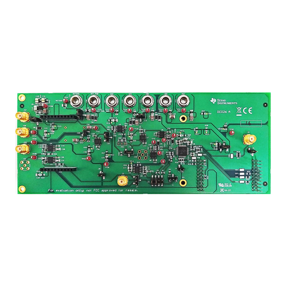
This user's guide describes the characteristics, operation, and use of the BP-DAC11001 evaluation
module (EVM) BoosterPack™ plug-in module. This EVM is designed to evaluate the performance of the
DAC11001
buffered voltage output DAC in a variety of configurations. Throughout this document, the
terms evaluation board, evaluation module, and EVM are synonymous with the BP-DAC11001EVM. This
document includes a schematic, reference printed-circuit board (PCB) layouts, and a complete bill of
materials.
.....................................................................................................................
1
1.1
1.2
2
2.1
2.2
3
3.1
3.2
4
4.1
BP-DAC11001EVM Schematic
4.2
PCB Layout
4.3
BP-DAC11001EVM Bill of Materials
1
BP-DAC11001EVM Software Setup
2
Software Installation Path
3
Launchpad Setup
4
TI Cloud Agent Installation
5
Hardware Setup
SLAU806 - October 2019
Submit Documentation Feedback
.........................................................................................................
................................................................................................................
.....................................................................................................
....................................................................................................
.........................................................................................................
.............................................................................................
.............................................................................................
.................................................................................
........................................................................................................
......................................................................................
..................................................................................................
............................................................................................................
.................................................................................................
..............................................................................................................
Copyright © 2019, Texas Instruments Incorporated
Contents
..............................................................
..........................................................................
............................................................................
List of Figures
User's Guide
SLAU806 - October 2019
BP-DAC11001EVM
BP-DAC11001EVM
3
3
3
4
4
6
8
8
10
16
16
20
23
4
4
5
5
6
1
Advertisement
Table of Contents

Related Manuals for Texas Instruments BP-DAC11001EVM


Summary of Contents for Texas Instruments BP-DAC11001EVM
-
Page 1: Table Of Contents
DAC in a variety of configurations. Throughout this document, the terms evaluation board, evaluation module, and EVM are synonymous with the BP-DAC11001EVM. This document includes a schematic, reference printed-circuit board (PCB) layouts, and a complete bill of materials. - Page 2 ..................BP-DAC11001EVM Jumper Settings ..................BP-DAC11001EVM Bill of Materials Trademarks BoosterPack is a trademark of Texas Instruments Inc. Windows is a trademark of Microsoft Corporation. All other trademarks are the property of their respective owners. BP-DAC11001EVM SLAU806 – October 2019 Submit Documentation Feedback Copyright ©...
-
Page 3: Overview
The following document provides information regarding Texas Instruments integrated circuits used in the assembly of the BP-DAC11001EVM. This user's guide is available from the TI web site under literature number SLAU806. Any letter appended to the literature number corresponds to the document revision that is current at the time of the writing of this document. -
Page 4: System Setup
EVM GUI; the runtime file can be downloaded through the EVM GUI during installation. The software can also be run online; however, only after the firmware and driver are upgraded. After the software is downloaded onto the PC, navigate to the download folder, and run the BP-DAC11001EVM software executable, as shown in Figure Figure 1. - Page 5 6. Press the Refresh or Finish button after the installation is complete. This action should detect the launchpad. 7. Press Start and browse for <Download Directory>\BP- DAC11001EVM_1.0.1_installer_win\install_image_BP-DAC11001EVM.\BP- DAC11001EVM\firmware\acctrl.bin. Press Load Image followed by Verify Image. SLAU806 – October 2019 BP-DAC11001EVM Submit Documentation Feedback Copyright © 2019, Texas Instruments Incorporated...
-
Page 6: Hardware Setup
Hardware Setup This section provides the overall system setup for the EVM. The hardware setup contains the MSP- EXP432E401Y launchpad and the BP-DAC11001EVM. A PC runs the software that provides an interface to the BP-DAC11001EVM through the launchpad. The BP-DAC11001EVM requires external power supplies, as described later in this document. The 3.3-V and 5-V power supplies from the launchpad can be used for IOVDD and DVDD for the DAC, respectively, using jumper options. - Page 7 2.2.3 Electrostatic Discharge Caution Many of the components on the BP-DAC11001EVM and the launchpad are susceptible to damage by electrostatic discharge (ESD). Observe proper ESD handling precautions when unpacking and handling the EVM, including the use of a grounded wrist strap at an approved ESD workstation.
-
Page 8: Detailed Description
The following subsections provide detailed information on the EVM hardware and jumper configuration settings. 3.1.1 Theory of Operation The block diagram of the BP-DAC11001EVM board is displayed in Figure 6. The dotted lines indicate different power and ground domains. All grounds are shorted together using single-point shorts. The EVM board connects to the launchpad with the BoosterPack connectors. - Page 9 Detailed Description www.ti.com 3.1.2 Signal Definition for the Launchpad Interface The BP-DAC11001EVM interfaces with the launchpad through connectors J9 and J10. The pin definitions are shown in Figure Pin aligns with BoosterPack pinout standard LD AC SDIN SCL K SYN C CL R Figure 7.
-
Page 10: Software Description
Options → Serial Port, and change the port to the other available port with the (Texas Instruments) or ACCtrl tag. One of the two ports with these tags will connect to the hardware. - Page 11 3.2.2 Software Features The BP-DAC11001EVM incorporates interactive functions that help configure the DAC11001 device. These functions are built into several GUI pages, as shown in the following sections. The Menu button allows the user to switch between the pages, with each page representing a feature of the software.
- Page 12 3.2.2.2 Setup Page The Setup page, shown in Figure 11, guides the user to perform a one-time firmware upgrade for the launchpad. Figure 11. Setup Page BP-DAC11001EVM SLAU806 – October 2019 Submit Documentation Feedback Copyright © 2019, Texas Instruments Incorporated...
- Page 13 (THD). Write a decimal code to the DAC output input box to get the corresponding analog output. Figure 12. DAC Quick-Start Page: Basic DAC Tab SLAU806 – October 2019 BP-DAC11001EVM Submit Documentation Feedback Copyright © 2019, Texas Instruments Incorporated...
- Page 14 Write Register or the Write All Registers button is pressed. By default, the Immediate update mode is selected for the Register Map page write operations. Figure 14. Register Page Options BP-DAC11001EVM SLAU806 – October 2019 Submit Documentation Feedback Copyright © 2019, Texas Instruments Incorporated...
- Page 15 Detailed Description www.ti.com 3.2.2.5 Collateral Page This page shown in Figure 15 provides links for all the collateral on the DAC11001 device. Figure 15. Collateral Page SLAU806 – October 2019 BP-DAC11001EVM Submit Documentation Feedback Copyright © 2019, Texas Instruments Incorporated...
- Page 16 Schematic, PCB Layout, and Bill of Materials www.ti.com Schematic, PCB Layout, and Bill of Materials This section contains the complete bill of materials and schematic diagram for the BP-DAC11001EVM. BP-DAC11001EVM Schematic Figure 16. Schematic Page 1 BP-DAC11001EVM SLAU806 – October 2019 Submit Documentation Feedback Copyright ©...
- Page 17 Schematic, PCB Layout, and Bill of Materials www.ti.com Figure 17. Schematic Page 2 SLAU806 – October 2019 BP-DAC11001EVM Submit Documentation Feedback Copyright © 2019, Texas Instruments Incorporated...
- Page 18 Schematic, PCB Layout, and Bill of Materials www.ti.com Figure 18. Schematic Page 3 BP-DAC11001EVM SLAU806 – October 2019 Submit Documentation Feedback Copyright © 2019, Texas Instruments Incorporated...
- Page 19 Schematic, PCB Layout, and Bill of Materials www.ti.com Figure 19. Schematic Page 4 SLAU806 – October 2019 BP-DAC11001EVM Submit Documentation Feedback Copyright © 2019, Texas Instruments Incorporated...
-
Page 20: Schematic, Pcb Layout, And Bill Of Materials
Schematic, PCB Layout, and Bill of Materials www.ti.com PCB Layout Figure 20 through Figure 25 show the layout details of the BP-DAC11001EVM board. Figure 20. PCB Components: Top Overlay Figure 21. PCB Components: Bottom Overlay BP-DAC11001EVM SLAU806 – October 2019 Submit Documentation Feedback... - Page 21 Schematic, PCB Layout, and Bill of Materials www.ti.com Figure 22. PCB Layout: Top Layer Figure 23. PCB Layout: Ground Plane SLAU806 – October 2019 BP-DAC11001EVM Submit Documentation Feedback Copyright © 2019, Texas Instruments Incorporated...
- Page 22 Schematic, PCB Layout, and Bill of Materials www.ti.com Figure 24. PCB Layout: Power Plane Figure 25. PCB Layout: Bottom Layer BP-DAC11001EVM SLAU806 – October 2019 Submit Documentation Feedback Copyright © 2019, Texas Instruments Incorporated...
- Page 23 Schematic, PCB Layout, and Bill of Materials www.ti.com BP-DAC11001EVM Bill of Materials Table 6 lists the EVM bill of materials (BOM). Table 6. BP-DAC11001EVM Bill of Materials Designator Quantity Value Description Package Reference Part Number Manufacturer Alternate Part Alternate Number...
- Page 24 Schematic, PCB Layout, and Bill of Materials www.ti.com Table 6. BP-DAC11001EVM Bill of Materials (continued) Designator Quantity Value Description Package Reference Part Number Manufacturer Alternate Part Alternate Number Manufacturer L1, L2, L3, L4, L5, L6, L7, 600 ohm Ferrite Bead, 600 ohm at...
- Page 25 Schematic, PCB Layout, and Bill of Materials www.ti.com Table 6. BP-DAC11001EVM Bill of Materials (continued) Designator Quantity Value Description Package Reference Part Number Manufacturer Alternate Part Alternate Number Manufacturer 20-/18-/16-Bit, Low Noise, PFB0048A DAC11001APFB Texas Instruments Ultra Low Harmonic Distortion, Fast Settling,...
- Page 26 STANDARD TERMS FOR EVALUATION MODULES Delivery: TI delivers TI evaluation boards, kits, or modules, including any accompanying demonstration software, components, and/or documentation which may be provided together or separately (collectively, an “EVM” or “EVMs”) to the User (“User”) in accordance with the terms set forth herein.
- Page 27 www.ti.com Regulatory Notices: 3.1 United States 3.1.1 Notice applicable to EVMs not FCC-Approved: FCC NOTICE: This kit is designed to allow product developers to evaluate electronic components, circuitry, or software associated with the kit to determine whether to incorporate such items in a finished product and software developers to write software applications for use with the end product.
- Page 28 www.ti.com Concernant les EVMs avec antennes détachables Conformément à la réglementation d'Industrie Canada, le présent émetteur radio peut fonctionner avec une antenne d'un type et d'un gain maximal (ou inférieur) approuvé pour l'émetteur par Industrie Canada. Dans le but de réduire les risques de brouillage radioélectrique à...
- Page 29 www.ti.com EVM Use Restrictions and Warnings: 4.1 EVMS ARE NOT FOR USE IN FUNCTIONAL SAFETY AND/OR SAFETY CRITICAL EVALUATIONS, INCLUDING BUT NOT LIMITED TO EVALUATIONS OF LIFE SUPPORT APPLICATIONS. 4.2 User must read and apply the user guide and other available documentation provided by TI regarding the EVM prior to handling or using the EVM, including without limitation any warning or restriction notices.
- Page 30 Notwithstanding the foregoing, any judgment may be enforced in any United States or foreign court, and TI may seek injunctive relief in any United States or foreign court. Mailing Address: Texas Instruments, Post Office Box 655303, Dallas, Texas 75265 Copyright © 2019, Texas Instruments Incorporated...
- Page 31 TI products. TI’s provision of these resources does not expand or otherwise alter TI’s applicable warranties or warranty disclaimers for TI products. Mailing Address: Texas Instruments, Post Office Box 655303, Dallas, Texas 75265 Copyright © 2019, Texas Instruments Incorporated...
Need help?
Do you have a question about the BP-DAC11001EVM and is the answer not in the manual?
Questions and answers