Advertisement
www.ti.com
EVM User's Guide: BQ51013CEVM
BQ51013C Evaluation Module
Description
The BQ51013CEVM is a wireless power receiver
based on the Qi standard of the Wireless Power
Consortium. The device complies with the Baseline
Power Profile (BPP) of 5W. Output voltage is 5V up
to 1A. The BQ51013CEVM contains the BQ51013C
IC and the support circuits needed to operate
the evaluation board. An external Qi transmitter is
required to power the EVM.
The receiver coil is a 48mm × 32mm coil mounted to
the plastic frame below the PCB. The case thickness
below coil to interface surface is 2mm.
SLUUD57 – OCTOBER 2024
Submit Document Feedback
Features
•
Supports WPC v2.0, BPP
•
Output voltage of 5V at 1A
•
Supports USB external input
•
Adjustable output current limit
•
Adjustable foreign object detection
Applications
•
True wireless headsets
•
Wearable accessories, smart band
•
Beauty and grooming
•
Electric toothbrush
Copyright © 2024 Texas Instruments Incorporated
Description
BQ51013C Evaluation Module
1
Advertisement
Table of Contents

Related Manuals for Texas Instruments BQ51013C


Summary of Contents for Texas Instruments BQ51013C
- Page 1 Supports USB external input Power Profile (BPP) of 5W. Output voltage is 5V up • Adjustable output current limit to 1A. The BQ51013CEVM contains the BQ51013C • Adjustable foreign object detection IC and the support circuits needed to operate Applications the evaluation board.
-
Page 2: Kit Contents
1.1 Introduction The BQ51013C is a wireless power supply and produces a 5V output of up to 1A for a 5W design. The device supports Qi version 2.0 and is a 5W Baseline Power Profile (BPP). The receiver is powered by a Qi compliant transmitter using the planer coil at the base of the EVM. -
Page 3: Best Practices
2.2 Printed Circuit Board Assembly The BQ51013C EVM PCB contains the BQ51013C EVM IC and support circuits. This board contains several jumpers and connectors. R16 provides the option to adjust current limit. EN1 / EN2 can be used to enable / disable the wireless power or AD external power input. - Page 4 TS - JP3 (3 pin header) Installed TS and FIXED PULLUP - JP4 (3 pin header) Installed PULLUP and Vz N/A - JP5 (2 pin header) BQ51013C Evaluation Module SLUUD57 – OCTOBER 2024 Submit Document Feedback Copyright © 2024 Texas Instruments Incorporated...
- Page 5 Hardware Table 2-2. Jumper Factory Settings (continued) I/O Connector Factory Setting ILIM - JP6 (3 pin header) Installed ILIM and FIX SLUUD57 – OCTOBER 2024 BQ51013C Evaluation Module Submit Document Feedback Copyright © 2024 Texas Instruments Incorporated...
- Page 6 Hardware Design Files www.ti.com 3 Hardware Design Files 3.1 Schematic The BQ51013C schematic is shown in Figure 3-1. SQ4949EY-T1-GE3 DC IN 5V, 1A 1μF 100nF 1μF AD-EN COM1 22nF TP15 CLMP1 470nF AD-EN RECT AD-EN RECT BOOT1 68nF CLMP1 CLAMP1...
-
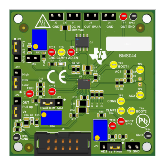
Page 7: Pcb Layout
Hardware Design Files 3.2 PCB Layout The board layout is shown in Figure 3-2 Figure 3-8. Figure 3-2. Top Overlay Figure 3-3. Top Solder SLUUD57 – OCTOBER 2024 BQ51013C Evaluation Module Submit Document Feedback Copyright © 2024 Texas Instruments Incorporated... - Page 8 Hardware Design Files www.ti.com Figure 3-4. Top Layer Figure 3-5. Bottom Layer BQ51013C Evaluation Module SLUUD57 – OCTOBER 2024 Submit Document Feedback Copyright © 2024 Texas Instruments Incorporated...
- Page 9 Hardware Design Files Figure 3-6. Bottom Solder Figure 3-7. Bottom Overlay SLUUD57 – OCTOBER 2024 BQ51013C Evaluation Module Submit Document Feedback Copyright © 2024 Texas Instruments Incorporated...
- Page 10 Hardware Design Files www.ti.com Figure 3-8. Drill Drawing BQ51013C Evaluation Module SLUUD57 – OCTOBER 2024 Submit Document Feedback Copyright © 2024 Texas Instruments Incorporated...
- Page 11 1 Coil, 1 Layer 14.3µH Wireless Charging Coil Inductor_48MM00_32MM 7.60308E+11 Wurth Electronics Receiver 190mOhm Max LBL1, LBL2 PCB Label 0.650 x 0.200 THT-14-423-10 Brady inch SLUUD57 – OCTOBER 2024 BQ51013C Evaluation Module Submit Document Feedback Copyright © 2024 Texas Instruments Incorporated...
- Page 12 RES, 200, 1%, 0.1 W, 0603 RC0603FR-07200RL Yageo Trimmer, 20k ohm, 0.25W, TH 4.5x8x6.7mm 3266W-1-203LF Bourns Unless otherwise noted, all parts can be substituted with equivalents. BQ51013C Evaluation Module SLUUD57 – OCTOBER 2024 Submit Document Feedback Copyright © 2024 Texas Instruments Incorporated...
-
Page 13: Additional Information
Additional Information 4 Additional Information 4.1 Trademarks All trademarks are the property of their respective owners. SLUUD57 – OCTOBER 2024 BQ51013C Evaluation Module Submit Document Feedback Copyright © 2024 Texas Instruments Incorporated... - Page 14 STANDARD TERMS FOR EVALUATION MODULES Delivery: TI delivers TI evaluation boards, kits, or modules, including any accompanying demonstration software, components, and/or documentation which may be provided together or separately (collectively, an “EVM” or “EVMs”) to the User (“User”) in accordance with the terms set forth herein.
- Page 15 www.ti.com Regulatory Notices: 3.1 United States 3.1.1 Notice applicable to EVMs not FCC-Approved: FCC NOTICE: This kit is designed to allow product developers to evaluate electronic components, circuitry, or software associated with the kit to determine whether to incorporate such items in a finished product and software developers to write software applications for use with the end product.
- Page 16 www.ti.com Concernant les EVMs avec antennes détachables Conformément à la réglementation d'Industrie Canada, le présent émetteur radio peut fonctionner avec une antenne d'un type et d'un gain maximal (ou inférieur) approuvé pour l'émetteur par Industrie Canada. Dans le but de réduire les risques de brouillage radioélectrique à...
- Page 17 www.ti.com EVM Use Restrictions and Warnings: 4.1 EVMS ARE NOT FOR USE IN FUNCTIONAL SAFETY AND/OR SAFETY CRITICAL EVALUATIONS, INCLUDING BUT NOT LIMITED TO EVALUATIONS OF LIFE SUPPORT APPLICATIONS. 4.2 User must read and apply the user guide and other available documentation provided by TI regarding the EVM prior to handling or using the EVM, including without limitation any warning or restriction notices.
- Page 18 Notwithstanding the foregoing, any judgment may be enforced in any United States or foreign court, and TI may seek injunctive relief in any United States or foreign court. Mailing Address: Texas Instruments, Post Office Box 655303, Dallas, Texas 75265 Copyright © 2023, Texas Instruments Incorporated...
- Page 19 TI products. TI’s provision of these resources does not expand or otherwise alter TI’s applicable warranties or warranty disclaimers for TI products. TI objects to and rejects any additional or different terms you may have proposed. IMPORTANT NOTICE Mailing Address: Texas Instruments, Post Office Box 655303, Dallas, Texas 75265 Copyright © 2024, Texas Instruments Incorporated...
Need help?
Do you have a question about the BQ51013C and is the answer not in the manual?
Questions and answers