Table of Contents
Advertisement
Quick Links
This user's guide details the hardware systems and operation of the Booster Pack for the BOOSTXL-
DRV8301 Motor Drive.
1
2
2.1
2.2
3
3.1
3.2
3.3
4
5
5.1
5.2
5.3
5.4
5.5
1
2
3
4
5
6
7
8
NexFET, InstaSPIN, TI are trademarks of Texas Instruments.
SLVU974 - October 2013
Submit Documentation Feedback
BOOSTXL-DRV8301 Hardware User's Guide
..................................................................................
.................................................................................
.............................................................................................................
................................................................................................................
..............................................................................................................
.......................................................................................................
.......................................................................................
.........................................................................................
...........................................................................................................
............................................................................................
..................................................................................
......................................................................................
......................................................................................
..........................................................................................................
......................................................................................................
........................................................................................................
....................................................................................
..............................................................................................
..............................................................................................
...............................................................................................
Copyright © 2013, Texas Instruments Incorporated
Contents
..............................................................................
........................................................................
List of Figures
................................................................
BOOSTXL-DRV8301 Hardware User's Guide
User's Guide
SLVU974 - October 2013
2
3
3
4
4
4
5
6
6
6
6
7
8
8
8
2
2
3
4
5
6
7
8
1
Advertisement
Table of Contents

Related Manuals for Texas Instruments BOOSTXL-DRV8301


Summary of Contents for Texas Instruments BOOSTXL-DRV8301
-
Page 1: Table Of Contents
..................LAUNCHXL-F28027F Configurations ....................Voltage Sense Configuration ....................Current Sense Configuration ....................OPA2374 External Amplifier NexFET, InstaSPIN, TI are trademarks of Texas Instruments. SLVU974 – October 2013 BOOSTXL-DRV8301 Hardware User's Guide Submit Documentation Feedback Copyright © 2013, Texas Instruments Incorporated... -
Page 2: Boostxl-Drv8301 Pcb (3-D Views)
BOOSTXL-DRV8301 PCB (3-D Views) www.ti.com BOOSTXL-DRV8301 PCB (3-D Views) The following views are 3-D models of the BOOSTXL-DRV8301 Motor Drive Booster Pack. Figure 1. PCB Top 3-D View Figure 2. PCB Bottom 3-D View BOOSTXL-DRV8301 Hardware User's Guide SLVU974 – October 2013 Submit Documentation Feedback Copyright ©... -
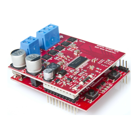
Page 3: Introduction To The Boostxl-Drv8301
Combine with compatible LaunchPad XL kits to create a complete 3-phase motor drive control platform • Optimized for the Piccolo LAUNCHXL-F28027F LaunchPad to support the InstaSPIN™ FOC sensorless control solution Figure 3. BOOSTXL-DRV8301 on Top of LAUNCHXL-F28027F SLVU974 – October 2013 BOOSTXL-DRV8301 Hardware User's Guide Submit Documentation Feedback... -
Page 4: Pinout
Getting Started www.ti.com Pinout The BOOSTXL-DRV8301 brings out a combination of power, control, and feedback signals to the XL LaunchPad headers. BOOSTXL-DRV8301 Pinout Signal Types POWER Viewed From Top GPIO Motor Motor To LaunchPad XL J1 To LaunchPad XL J2... -
Page 5: Configuring The Launchpad
LaunchPad that connects the 3.3-V emulation and controller power supplies. The BOOSTXL-DRV8301 nFAULT and nOCTW signals share lines with the LaunchPad UART RX and TX signals. To see proper nFAULT and nOCTW reporting on the onboard LEDs and microcontroller GPIO, disconnect the UART lines from the emulation side of the LaunchPad to the microcontroller. -
Page 6: Connecting The Hardware
Detailed Hardware Description The BOOSTXL-DRV8301 Motor Drive Booster Pack is a complete drive stage for a 3-phase application. This Motor Drive Booster Pack consists of the DRV8301 pre-driver and CSD18533Q5A N-Channel NexFET™ Power MOSFETs. See the respective data sheets for the... -
Page 7: Low-Side Current Shunt Sense
8, is set to closely mirror the internal amplifiers of the DRV8301. The gain is set to 10 with a reference voltage of approximately 1.65 V. SLVU974 – October 2013 BOOSTXL-DRV8301 Hardware User's Guide Submit Documentation Feedback Copyright © 2013, Texas Instruments Incorporated... -
Page 8: Booster Pack Pwm Signals
Hardware Files (Schematic and Gerber) The complete design files are in the tool folder (www.ti.com/drv8301-boosterpack) including the schematic, Gerbers, layout files, PCB views, and bill of materials. BOOSTXL-DRV8301 Hardware User's Guide SLVU974 – October 2013 Submit Documentation Feedback Copyright © 2013, Texas Instruments Incorporated... - Page 9 Any exceptions to this are strictly prohibited and unauthorized by Texas Instruments unless user has obtained appropriate experimental/development licenses from local regulatory authorities, which is responsibility of user including its acceptable authorization.
- Page 10 FCC Interference Statement for Class B EVM devices This equipment has been tested and found to comply with the limits for a Class B digital device, pursuant to part 15 of the FCC Rules. These limits are designed to provide reasonable protection against harmful interference in a residential installation. This equipment generates, uses and can radiate radio frequency energy and, if not installed and used in accordance with the instructions, may cause harmful interference to radio communications.
- Page 11 Also, please do not transfer this product, unless you give the same notice above to the transferee. Please note that if you could not follow the instructions above, you will be subject to penalties of Radio Law of Japan. Texas Instruments Japan Limited (address) 24-1, Nishi-Shinjuku 6 chome, Shinjuku-ku, Tokyo, Japan http://www.tij.co.jp...
- Page 12 FDA Class III or similar classification, then you must specifically notify TI of such intent and enter into a separate Assurance and Indemnity Agreement. Mailing Address: Texas Instruments, Post Office Box 655303, Dallas, Texas 75265 Copyright © 2013, Texas Instruments Incorporated...
- Page 13 IMPORTANT NOTICE Texas Instruments Incorporated and its subsidiaries (TI) reserve the right to make corrections, enhancements, improvements and other changes to its semiconductor products and services per JESD46, latest issue, and to discontinue any product or service per JESD48, latest issue.
Need help?
Do you have a question about the BOOSTXL-DRV8301 and is the answer not in the manual?
Questions and answers