Table of Contents
Advertisement
Quick Links
www.ti.com
EVM User's Guide: BP-CC3301
SimpleLink
™
BoosterPack
Description
The SimpleLink
™
CC3301 Wi-Fi 6 and Bluetooth
Low Energy devices enable affordable, reliable and
secure connectivity in embedded applications with
a processor host running Linux
running RTOS. The CC3301 BoosterPack
module (BP-CC3301) is a test and development
board that can be easily connected to TI LaunchPad
development kits or processor boards; thus enabling
rapid software development.
SWAU130A – MARCH 2023 – REVISED DECEMBER 2023
Submit Document Feedback
CC3301 Wi-Fi 6 and Bluetooth
™
Plug-in Module (BP-CC3301)
®
®
or an MCU host
™
plug-in
Copyright © 2023 Texas Instruments Incorporated
Features
•
CC3301 Wi-Fi 6
combo device
•
Two 20-pin stackable connectors (BoosterPack
Standard)
•
Onboard chip dual-band antenna
•
SMA/U.FL connector for conducted RF testing
™
•
Power from on board dual rail (3.3 V and 1.8 V)
LDO using USB or LaunchPad ™
•
3 level shifters for voltage translation (3.3 V to 1.8
V)
•
JTAG header pins for SWD interface with XDS110
or LP-XDS110
•
Jumper for current measurement on both power
supplies (3.3 V and 1.8 V) with provision to mount
0.1 ohm (0603) resistors for measurement with
voltmeter
•
32 kHz oscillator for lower power evaluation
SimpleLink
™
CC3301 Wi-Fi 6 and Bluetooth
®
Low Energy
®
and Bluetooth Low Energy
®
Low Energy BoosterPack
™
in Module (BP-CC3301)
Description
Plug-
1
Advertisement
Table of Contents

Related Manuals for Texas Instruments BP-CC3301


Summary of Contents for Texas Instruments BP-CC3301
-
Page 1: Description
Standard) running RTOS. The CC3301 BoosterPack ™ plug-in • Onboard chip dual-band antenna module (BP-CC3301) is a test and development • SMA/U.FL connector for conducted RF testing board that can be easily connected to TI LaunchPad ™ • Power from on board dual rail (3.3 V and 1.8 V) development kits or processor boards;... -
Page 2: Table Of Contents
LP-AM243............................12 Figure 3-2. BeagleBone Black Board............................Figure 3-3. Adapter Board for the BeagleBone Black........................13 Figure 3-4. BP-CC3301 + BBB with Adapter Board........................Figure 3-5. Top View of Modified BBB............................Figure 3-6. Bottom View of Modified BBB..........................15 Figure 3-7. BP-CC3301 Connected to LP-XDS110 (ET)...................... -
Page 3: Evaluation Module Overview
2. Processor and Linux evaluation: BP-CC3301 + BP-CC33-BBB-ADAPT + BEAGL-BONE-BLACK. 3. RF-testing with PC tools: BP-CC3301 + LP-XDS110. In addition, the BP-CC3301 can also be wired to any other Linux or RTOS host board running TCP/IP stack. Refer to Section 3.1 for more information. -
Page 4: Hardware
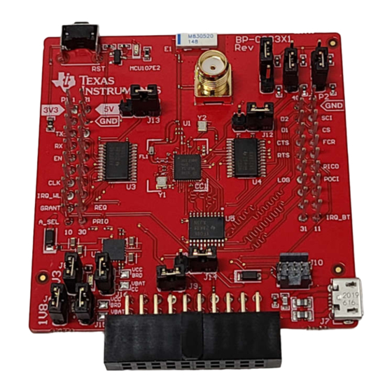
Hardware www.ti.com 2 Hardware Figure 2-1 shows the overview of the BP-CC3301. Chip Antenna Connector 20 Pin 20 Pin BoosterPack™ BoosterPack™ Connector (P1) Connector (P2) CC3301 Engine Area Wi-Fi 6 and Bluetooth® Low Energy Companion IC Level Shifters Dual Rail... -
Page 5: Connector And Jumper Descriptions
2 X 20 pins each connected to LaunchPad. See Section 2.2.3. SWAU130A – MARCH 2023 – REVISED DECEMBER 2023 SimpleLink ™ CC3301 Wi-Fi 6 and Bluetooth ® Low Energy BoosterPack ™ Plug- Submit Document Feedback in Module (BP-CC3301) Copyright © 2023 Texas Instruments Incorporated... -
Page 6: Figure 2-3. Bp-Cc3301 Boosterpack Header Pinout
P1.7: SDIO_CLK P2.14:SDIO_D0 (POCI) P2.34:LOGGER P1.8: IRQ_WL P1.9: COEX_GRANT P1.29: COEX_REQ P2.11:IRQ_BLE_3V3 P1.10: ANT_SEL P1.30: COEX_PRIORITY Figure 2-3. BP-CC3301 BoosterPack Header Pinout Table 2-3. P1 Header Pin Assignment Name (in schematic) Type/ Direction Description P1.1 VCC_MCU_3V3 Input No functional purpose. -
Page 7: Table 2-4. P2 Header Pin Assignment
SDIO_D2_3V3 Input/Output SDIO data D2. P2.40 Reserved SWAU130A – MARCH 2023 – REVISED DECEMBER 2023 SimpleLink ™ CC3301 Wi-Fi 6 and Bluetooth ® Low Energy BoosterPack ™ Plug- Submit Document Feedback in Module (BP-CC3301) Copyright © 2023 Texas Instruments Incorporated... -
Page 8: Figure 2-4. Arm 10 Pin Jtag Connector (J10)
The signal assignment for these headers are described in the figures and tables below. The main JTAG interface for the BP-CC3301 is via the LP-XDS110 (ET) that is connected to the 20pin header (J11). A XDS110 debug probe can also interface with this board via a 10-pin header (J10), however this header is not populated with the default kit. -
Page 9: Power
, which can be as high as 500 mA. In such cases, the USB connector (J7) on the BP-CC3301 can be used to aid in extra current. The use of Schottky diodes make sure that load sharing occurs between the USB connectors on the LaunchPad kit and the BoosterPack module without any board modifications. -
Page 10: Figure 2-7. Active Current Measurement
2-8). Similar operation with J16 and 3.3V supply. Figure 2-7. Active Current Measurement SimpleLink ™ CC3301 Wi-Fi 6 and Bluetooth ® Low Energy BoosterPack ™ Plug- SWAU130A – MARCH 2023 – REVISED DECEMBER 2023 in Module (BP-CC3301) Submit Document Feedback Copyright © 2023 Texas Instruments Incorporated... -
Page 11: Clocking
As seen in Figure 2-9, the BP-CC3301 has an on-board SMA connector and component antenna. The SMA connector (J1) provides a way for testing conducted measurements. Alternately, a track pad for a U.FL connector (J2) is provided on-board to replace the SMA connector and provide a way to test in the lab using a... -
Page 12: Implementation Results
• RF testing with PC tools: BP-CC3301 + LP-XDS110 In addition, the BP-CC3301 can also be wired to any other Linux or RTOS host board running TCP/IP stack. 3.1.1 MCU and RTOS The BP-CC3301 can be used with a MCU running TCP/IP, like the LP-AM243 and can easily integrate with the... -
Page 13: Figure 3-2. Beaglebone Black Board
Implementation Results 3.1.2 Processor and Linux The BP-CC3301 can integrate with a host platform running Linux OS, like the BeagleBone Black (BBB). The BeagleBone Black is a low-cost, community-supported development platform as shown below. Figure 3-2. BeagleBone Black Board... -
Page 14: Figure 3-4. Bp-Cc3301 + Bbb With Adapter Board
Implementation Results www.ti.com Figure 3-4. BP-CC3301 + BBB with Adapter Board To make sure the BeagleBone Black boots up from the SD card, TI recommends to add a 100k Ohm resistor for R93 on the top of the BBB, and remove the R68 resistor seen on the bottom of the BBB. Alternatively, you can press and hold the S2 button on the BeagleBone board during power up if the hardware modifications were not made. -
Page 15: Figure 3-6. Bottom View Of Modified Bbb
Figure 3-6. Bottom View of Modified BBB 3.1.3 Standalone RF Testing The BP-CC3301 can be used standalone (without a host) to test RF capabilities, using Radio Tool. For more information on Radio Tool and where to download, refer to Wi-Fi Toolbox BP-CC3301 Hardware Setup. -
Page 16: Figure 3-7. Bp-Cc3301 Connected To Lp-Xds110 (Et)
Figure 3-7. This verifies that the target voltage for the JTAG signals are sourced from the BP-CC3301 (which is 1.8V) instead of the default LP-XDS110 target voltage (3.3V). Power supply for the BP-CC3301 comes from the LP-XDS110 in this case, but there can be usage scenarios where additional current is needed from the USB connection (J7). -
Page 17: Hardware Design Files
Request more information section. Request Now. 4.2 PCB Layouts To access the Gerber files for the BP-CC3301, the user can submit a request on the ti.com CC3301 tool folder under Request more information section. Request Now. 4.3 Bill of Materials (BOM) To access the BOM list for the BP-CC3301, the user can submit a request on the ti.com CC3301 tool folder... - Page 18 STANDARD TERMS FOR EVALUATION MODULES Delivery: TI delivers TI evaluation boards, kits, or modules, including any accompanying demonstration software, components, and/or documentation which may be provided together or separately (collectively, an “EVM” or “EVMs”) to the User (“User”) in accordance with the terms set forth herein.
- Page 19 www.ti.com Regulatory Notices: 3.1 United States 3.1.1 Notice applicable to EVMs not FCC-Approved: FCC NOTICE: This kit is designed to allow product developers to evaluate electronic components, circuitry, or software associated with the kit to determine whether to incorporate such items in a finished product and software developers to write software applications for use with the end product.
- Page 20 www.ti.com Concernant les EVMs avec antennes détachables Conformément à la réglementation d'Industrie Canada, le présent émetteur radio peut fonctionner avec une antenne d'un type et d'un gain maximal (ou inférieur) approuvé pour l'émetteur par Industrie Canada. Dans le but de réduire les risques de brouillage radioélectrique à...
- Page 21 www.ti.com EVM Use Restrictions and Warnings: 4.1 EVMS ARE NOT FOR USE IN FUNCTIONAL SAFETY AND/OR SAFETY CRITICAL EVALUATIONS, INCLUDING BUT NOT LIMITED TO EVALUATIONS OF LIFE SUPPORT APPLICATIONS. 4.2 User must read and apply the user guide and other available documentation provided by TI regarding the EVM prior to handling or using the EVM, including without limitation any warning or restriction notices.
- Page 22 Notwithstanding the foregoing, any judgment may be enforced in any United States or foreign court, and TI may seek injunctive relief in any United States or foreign court. Mailing Address: Texas Instruments, Post Office Box 655303, Dallas, Texas 75265 Copyright © 2023, Texas Instruments Incorporated...
- Page 23 TI products. TI’s provision of these resources does not expand or otherwise alter TI’s applicable warranties or warranty disclaimers for TI products. TI objects to and rejects any additional or different terms you may have proposed. IMPORTANT NOTICE Mailing Address: Texas Instruments, Post Office Box 655303, Dallas, Texas 75265 Copyright © 2023, Texas Instruments Incorporated...
Need help?
Do you have a question about the BP-CC3301 and is the answer not in the manual?
Questions and answers