Table of Contents
Advertisement
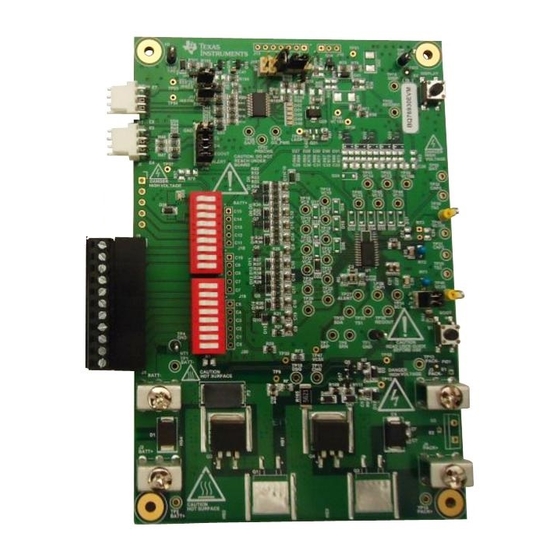
The bq76920EVM evaluation module (EVM) is a complete evaluation system for the bq76920, a 3-cell to
5-cell Li-Ion battery analog front end (AFE) integrated circuit. The EVM consists of a bq76920 circuit
module which is used for simple evaluation of the bq76920 functions. The circuit module includes one
bq76920 integrated circuit (IC), sense resistor, power FETs, and all other onboard components necessary
to protect the cells from overcharge, over discharge, short circuit, and overcurrent discharge in a 5-series
cell Li-Ion or Li-Polymer battery pack. The circuit module connects directly across the cells in a battery.
With a compatible interface board and Microsoft
software, the user can view the bq76920 registers, adjust protection limits and enable FET control outputs.
.......................................................................................................................
1
1.1
1.2
1.3
1.4
2
2.1
2.2
3
3.1
3.2
3.3
3.4
4
4.1
4.2
4.3
4.4
4.5
4.6
4.7
5
5.1
5.2
6
1
2
3
4
5
6
7
8
Microsoft, Windows are registered trademarks of Microsoft Corporation.
Submit Documentation Feedback
bq76920 Evaluation Module User's Guide
..........................................................................................................
...............................................................................................
................................................................................................
..........................................................................................
...................................................................................................
...........................................................................................................
....................................................................................
..............................................................................................
....................................................................................................
.................................................................................................
..............................................................................................
......................................................................................................
.........................................................................................
..................................................................................................
.............................................................................................
.....................................................................................................
.............................................................................................
.......................................................................................................
....................................................................................................
.....................................................................................
...............................................................................................................
.................................................................................................................
.............................................................................................................
..................................................................................................
.............................................................................................................
...............................................................................................................
Copyright © 2014, Texas Instruments Incorporated
SLVU924B - March 2014 - Revised April 2014
Windows
based PC graphical user interface (GUI)
®
®
Contents
...............................................
...........................................................
..............................................................................
...................................................................
..........................................................................
List of Figures
..............................................................
User's Guide
2
2
2
3
3
3
3
4
5
5
5
5
6
11
11
11
12
13
13
13
13
15
15
23
29
5
6
8
9
10
12
15
16
1
Advertisement
Table of Contents

Subscribe to Our Youtube Channel
Related Manuals for Texas Instruments bq76940


Summary of Contents for Texas Instruments bq76940
-
Page 1: Table Of Contents
Simulating Current Setup ......................Top Silk Screen ....................... Top Assembly Microsoft, Windows are registered trademarks of Microsoft Corporation. SLVU924B – March 2014 – Revised April 2014 bq76920 Evaluation Module User's Guide Submit Documentation Feedback Copyright © 2014, Texas Instruments Incorporated... -
Page 2: Features
EVM to a 1P or 2P battery construction. Refer to the physical construction section for board details. bq76920 Evaluation Module User's Guide SLVU924B – March 2014 – Revised April 2014 Submit Documentation Feedback Copyright © 2014, Texas Instruments Incorporated... -
Page 3: Bq76920 Circuit Module Performance Specification Summary
• TI EV2300 or EV2400 interface board • Computer with USB port and compatible Windows operating system and access to the internet • TI bq76940/bq76930/bq76920 Evaluation Software (see Section • Test leads to connect equipment • Electronic load or assorted resistors Additional equipment may be desired to operate the bq76920 with a more extensive demonstration. -
Page 4: Quick Start
Refer to Figure 1 for the following steps. 1. Install the bq76940/bq76930/bq76920 evaluation software. Software is obtained from www.ti.com. Install drivers for the EV2300, if necessary. 2. Remove shunts from headers connecting the AFE to the gauge. 3. If the EV2300 is used, install shunts on the SCL and SDA pull-up headers. Remove any pull-up shunts when using the EV2400. -
Page 5: Bq76940/Bq76930/Bq76920 Software
FETs without control, the bq76940/bq76930/bq76920 software provides that control from the GUI. The software may also be identified as bq76940 or bq769X0 in menus or windows as space permits. System Requirements The bq76940/bq76930/bq76920 software requires a Windows 7, or later operating system. The computer must also have Microsoft .NET connection software version 4.0, or higher, installed. -
Page 6: Software Operation
Figure The bq76940/bq76930/bq76920 software uses popup help tips on many of the control features. Figure 2. bq76940/bq76930/bq76920 Evaluation Software Display The software window contains a menu bar and 3 sections. The top section is an I2C tool. The middle section has 3 selectable views. - Page 7 3. It shows the control register values. If another view is displayed it is selected using the Registers button on the left side of the window or from the menu. SLVU924B – March 2014 – Revised April 2014 bq76920 Evaluation Module User's Guide Submit Documentation Feedback Copyright © 2014, Texas Instruments Incorporated...
-
Page 8: Registers View
The Read Device button at the top of the Registers view provides important setup of the bq76940/bq76930/bq76920 software and the IC. The software reads the factory gain and offset data from the device and populates these in the Stack V/T/I section for use in calculating display values. The software writes the CC_CFG register to its proper value and also detects the CRC mode of the device and sets the software appropriately. -
Page 9: I2C Pro View
The Logging section has the Start Logging button. The values read from the device can be saved to a file. Selecting the Start Logging button opens a bq76940 Logging popup window to enter the file name, comments and to select the data groups to be logged. The file name must be entered with the pop up window's Browse button. -
Page 10: Sequence View
The Set UV Trip... file shows an example of a simpler format. Sequence files are installed to: C:\Users\<account-name>\Documents\Texas Instruments\bq76940\sequence. Sequences are loaded from this location when the program starts. Create new sequences with a text editor and save them with the .bqseq extension. -
Page 11: Bq76920 Circuit Module Use
3.4.8 Operation with Other interfaces or Hosts The bq76940/bq76930/bq76920 software does not support other interface boards or adapters other than the EV2300 and EV2400. The software does not operate in a multi-master environment. If operated with another host on the line, data collisions can occur. Also be aware that the EV2400 has internal pull-up resistors to 3.3 V, connecting to some shared busses could damage devices on that bus if the bus voltage... -
Page 12: Reducing The Cell Count
(Numbered from Bottom Cell 1) Cell 4 C4 to C3 VC4 to VC3 Cell 3 C3 to C2 VC3 to VC2 bq76920 Evaluation Module User's Guide SLVU924B – March 2014 – Revised April 2014 Submit Documentation Feedback Copyright © 2014, Texas Instruments Incorporated... -
Page 13: Connecting Cells
4. Open the cell simulator switches, if needed When using external balancing with P-channel MOSFETs, such as on the bq76930 and bq76940 EVMs, the inrush current for a cell can momentarily turn on the balance FET causing the next cell input below to rise. - Page 14 HS1 is a position to mount a suitable heatsink, if needed. Other heatsink options may be available in the evaluation environment. bq76920 Evaluation Module User's Guide SLVU924B – March 2014 – Revised April 2014 Submit Documentation Feedback Copyright © 2014, Texas Instruments Incorporated...
-
Page 15: Bq76920Evm Circuit Module Physical Construction
See additional information in the configuration and operation sections of this document. Figure 7 Figure 14 show the board layout. Figure 7. Top Silk Screen SLVU924B – March 2014 – Revised April 2014 bq76920 Evaluation Module User's Guide Submit Documentation Feedback Copyright © 2014, Texas Instruments Incorporated... -
Page 16: Top Assembly
Circuit Module Physical Construction www.ti.com Figure 8. Top Assembly bq76920 Evaluation Module User's Guide SLVU924B – March 2014 – Revised April 2014 Submit Documentation Feedback Copyright © 2014, Texas Instruments Incorporated... - Page 17 Circuit Module Physical Construction www.ti.com Figure 9. Top Layer SLVU924B – March 2014 – Revised April 2014 bq76920 Evaluation Module User's Guide Submit Documentation Feedback Copyright © 2014, Texas Instruments Incorporated...
-
Page 18: Layer
Circuit Module Physical Construction www.ti.com Figure 10. Layer 2 bq76920 Evaluation Module User's Guide SLVU924B – March 2014 – Revised April 2014 Submit Documentation Feedback Copyright © 2014, Texas Instruments Incorporated... -
Page 19: Layer
Circuit Module Physical Construction www.ti.com Figure 11. Layer 3 SLVU924B – March 2014 – Revised April 2014 bq76920 Evaluation Module User's Guide Submit Documentation Feedback Copyright © 2014, Texas Instruments Incorporated... -
Page 20: Bottom Layer
Circuit Module Physical Construction www.ti.com Figure 12. Bottom Layer bq76920 Evaluation Module User's Guide SLVU924B – March 2014 – Revised April 2014 Submit Documentation Feedback Copyright © 2014, Texas Instruments Incorporated... -
Page 21: Bottom Silk Screen
Circuit Module Physical Construction www.ti.com Figure 13. Bottom Silk Screen SLVU924B – March 2014 – Revised April 2014 bq76920 Evaluation Module User's Guide Submit Documentation Feedback Copyright © 2014, Texas Instruments Incorporated... -
Page 22: Bottom Assembly
Circuit Module Physical Construction www.ti.com Figure 14. Bottom Assembly bq76920 Evaluation Module User's Guide SLVU924B – March 2014 – Revised April 2014 Submit Documentation Feedback Copyright © 2014, Texas Instruments Incorporated... -
Page 23: Bill Of Materials
Vishay-Dale R15, R18, R19, R47, R54, R59, R60 1.00Meg RES, 1.00Meg ohm, 1%, 0.125W, 0805 0805 CRCW08051M00FKEA Vishay-Dale SLVU924B – March 2014 – Revised April 2014 bq76920 Evaluation Module User's Guide Submit Documentation Feedback Copyright © 2014, Texas Instruments Incorporated... -
Page 24: Bq76920 Circuit Module
RES, 1.00Meg ohm, 1%, 0.125W, 0805 0805 CRCW08051M00FKEA Vishay-Dale Black Test Point, TH, Multipurpose, Black Keystone5011 5011 Keystone bq76920 Evaluation Module User's Guide SLVU924B – March 2014 – Revised April 2014 Submit Documentation Feedback Copyright © 2014, Texas Instruments Incorporated... -
Page 25: Bq76920 Circuit Module
5012 Keystone TP13, TP14, TP15, TP18, TP20, TP21, TP22, TP24, TP25, TP26, TP27, TP28, TP33, TP34, TP35, TP37 SLVU924B – March 2014 – Revised April 2014 bq76920 Evaluation Module User's Guide Submit Documentation Feedback Copyright © 2014, Texas Instruments Incorporated... -
Page 26: Schematic Diagram Afe
0 - 15 A 0 - 15 A 0.1µF 0.1µF 0.1µF BATT+ BATT+ TP29 108-0740-001 108-0740-001 Figure 15. Schematic Diagram AFE bq76920 Evaluation Module User's Guide SLVU924B – March 2014 – Revised April 2014 Submit Documentation Feedback Copyright © 2014, Texas Instruments Incorporated... -
Page 27: Schematic Diagram Gauge
3300pF 3300pF 25 ppm/C 1.25V BATT– 10.0k TP32 MMSZ5246B-7-F 1.00Meg PACK– 1.0k BSS138 Figure 16. Schematic Diagram Gauge SLVU924B – March 2014 – Revised April 2014 bq76920 Evaluation Module User's Guide Submit Documentation Feedback Copyright © 2014, Texas Instruments Incorporated... -
Page 28: Schematic Diagram Cell Simulator
Circuit Module Physical Construction www.ti.com BATT+ 1.00k 76SB07ST 1.00k Orange Test points BATT– Figure 17. Schematic Diagram Cell Simulator bq76920 Evaluation Module User's Guide SLVU924B – March 2014 – Revised April 2014 Submit Documentation Feedback Copyright © 2014, Texas Instruments Incorporated... -
Page 29: Related Documents From Texas Instruments
Revision History Changes from A Revision (April 2014) to B Revision ....................Page • Changed software title to bq76940/bq76930/bq76920 Evaluation Software in step one of the Quick Start section and ......................globally throughout document..• Added clarification about device identifiers in menus or windows in the bq76940/bq76930/bq76920 Software section ........ - Page 30 ADDITIONAL TERMS AND CONDITIONS, WARNINGS, RESTRICTIONS, AND DISCLAIMERS FOR EVALUATION MODULES Texas Instruments Incorporated (TI) markets, sells, and loans all evaluation boards, kits, and/or modules (EVMs) pursuant to, and user expressly acknowledges, represents, and agrees, and takes sole responsibility and risk with respect to, the following: 1.
- Page 31 RADIO FREQUENCY REGULATORY COMPLIANCE INFORMATION FOR EVALUATION MODULES Texas Instruments Incorporated (TI) evaluation boards, kits, and/or modules (EVMs) and/or accompanying hardware that is marketed, sold, or loaned to users may or may not be subject to radio frequency regulations in specific countries.
- Page 32 Les types d'antenne non inclus dans cette liste, ou dont le gain est supérieur au gain maximal indiqué, sont strictement interdits pour l'exploitation de l'émetteur. Mailing Address: Texas Instruments, Post Office Box 655303, Dallas, Texas 75265 Copyright © 2014, Texas Instruments Incorporated spacer Important Notice for Users of EVMs Considered “Radio Frequency Products”...
-
Page 33: Important Notice
IMPORTANT NOTICE Texas Instruments Incorporated and its subsidiaries (TI) reserve the right to make corrections, enhancements, improvements and other changes to its semiconductor products and services per JESD46, latest issue, and to discontinue any product or service per JESD48, latest issue. - Page 34 Mouser Electronics Authorized Distributor Click to View Pricing, Inventory, Delivery & Lifecycle Information: Texas Instruments BQ76920EVM...
Need help?
Do you have a question about the bq76940 and is the answer not in the manual?
Questions and answers